-
+86 13720060320
-
lanna@haitangs.com

How to Specify Industrial Control Panel Door Hinges: Door Load, Cable Clearance & Service Access
A control-panel door can close correctly in CAD and still become difficult to use after the cabinet is wired. Add an HMI, selector switches, meters, cable harnesses, a bonding strap and internal wire duct, and the moving assembly is no longer the empty sheet-metal door used during the first layout.
The hinge may fit every mounting hole and still create a problem. The finished door can sag because its center of gravity moved outward. A cable loop can become tight halfway through the swing. A 90° opening may look generous until a technician tries to remove a component behind the door. A concealed hinge may fit when closed but sweep into a wire duct as it opens.
Specifying industrial control panel door hinges therefore starts with the complete cabinet door and the work that must happen around it. Finished door load, hinge position, mounting stiffness, cable movement, closed-door alignment and service access all need to agree before a hinge model is released.
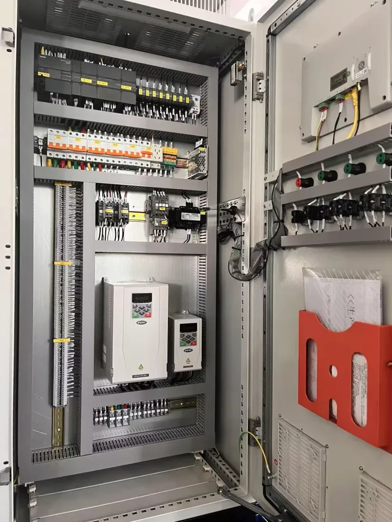
Start With the Finished Control-Panel Door
The empty door panel is only the structural starting point. The hinge works with the production door: everything mounted to it, everything connected across the hinge side and every force that changes when the door moves.
Door-mounted equipment may include an HMI, pushbuttons, indicators, meters, disconnect hardware, ventilation components, document pockets, handles, wiring and protective covers. Their locations matter as much as their mass. A component mounted near the latch side changes the center of gravity more than the same mass placed close to the hinge line.
This is why “door weight” should mean the completed moving assembly for hinge selection. When several cabinet variants share the same sheet-metal door, do not automatically assign one mass or load condition to the entire family. The heaviest version may not have the farthest center of gravity, and the version with the greatest mass may not create the worst mounting reaction.
| Control-Panel Input | Why the Hinge Design Needs It | Engineering Action |
|---|---|---|
| Finished door mass | Defines the moving load after door-mounted equipment is installed | Use the production-intent door configuration |
| Door height and width | Affects hinge spacing, structural stiffness and load path | Use the final door envelope, not only the cabinet opening |
| Center of gravity | Shows how far the combined door load acts from the hinge line | Include mounted components when estimating its position |
| Hinge quantity and spacing | Changes load distribution and sensitivity to alignment | Position hinges from the complete door structure |
| Mounting material and thickness | Determines how hinge reactions enter the door and frame | Identify the actual flange, reinforcement or frame section |
| Required service access | Defines the usable opening range rather than the catalog angle alone | List the maintenance tasks performed with the door open |
| Cable and bonding path | Can limit rotation or add unwanted force to the moving door | Map fixed and moving attachment points through the full swing |
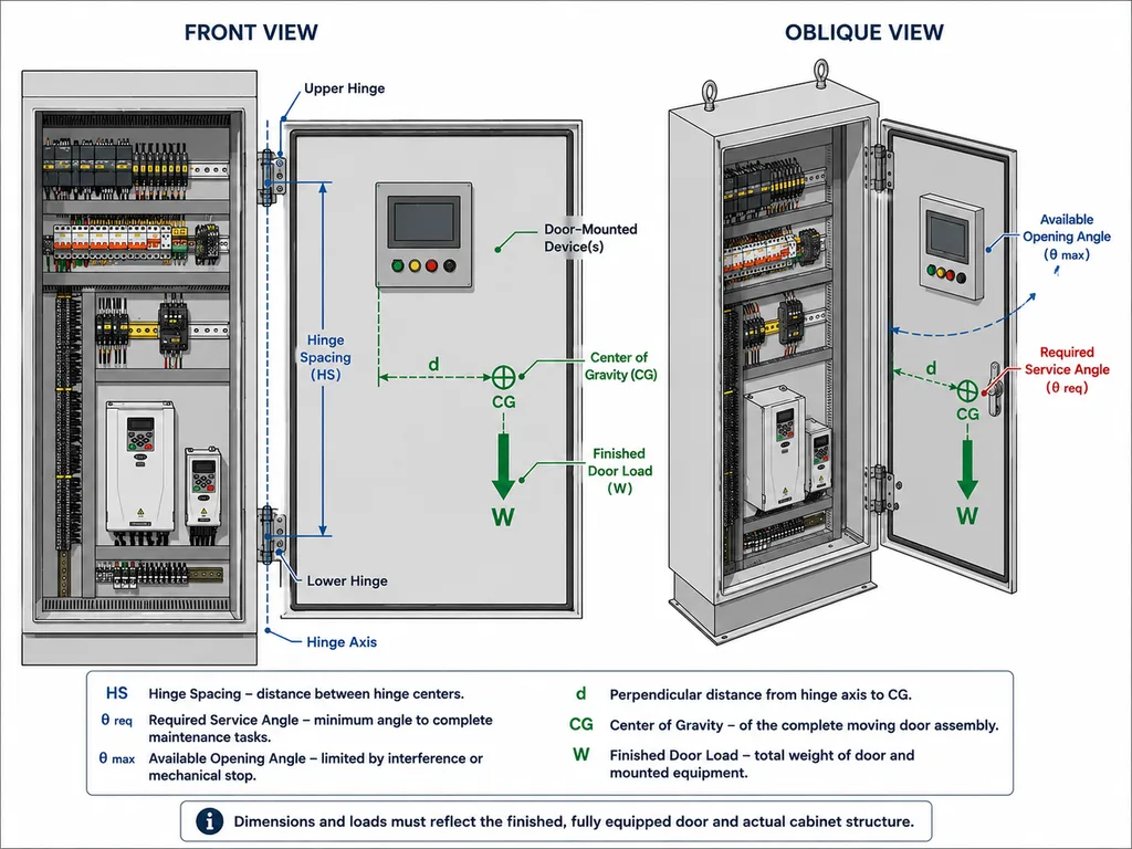
Do not divide the finished door weight by the number of hinges and treat that result as the complete requirement. Hinge spacing, door stiffness, frame stiffness, center-of-gravity position, mounting geometry and installation orientation all affect the reactions at the hinge points.
The important number is not the weight of the sheet-metal blank. Use the finished moving door, then review where that mass sits relative to the hinge axis and how the hinge reactions enter the frame.
The distinction between an application load case and a catalog capacity value is covered separately in our guide to industrial hinge load ratings.
The Hinge Line and Mounting Structure
Follow the load beyond the hinge leaf. On a fabricated control cabinet, the useful load path may continue through a formed door return, fasteners, a reinforcement plate, a frame flange and finally the cabinet structure. The visible sheet is not always the structural member carrying the hinge reaction.
This becomes especially important with thin sheet metal. Tightening a hinge onto an unsupported skin can locally dish the panel. Two mounting faces that looked aligned before tightening can move after clamp load is applied. With several hinges on a tall door, small changes at individual mounting points can move the practical rotation axes away from one another and create binding.
Look at both sides of the joint. The door-side leaf needs a stable base, but the cabinet-side leaf also needs enough support. A strong reinforcement behind the door does not solve a flexible frame flange.
When the door or frame flange is thin, the mounting joint may need a backing plate, threaded insert, through-bolt, self-clinching hardware or reinforced formed section. The appropriate joint depends on the actual sheet, load and rear-access condition; the detailed mounting decision is covered in our guide to thin sheet-metal hinge mounting.
Fastener access deserves the same early check. A hinge can be structurally suitable and still be impossible to install after a DIN rail, wire duct or internal panel blocks the driver or wrench path. On serviceable equipment, installation access is part of the hinge interface, not an afterthought.
Gasket, Latch and Interlock Alignment
A control-panel hinge does more than carry the door while it is open. It also has to return the closed door to a repeatable relationship with the cabinet frame.
Small changes at the hinge side can appear much larger at the latch side. Door sag, flange distortion, unequal hinge seating or a shifted hinge axis can change the door gap even when the hinge itself still rotates freely. The result may show up as uneven gasket compression, harder handle operation or a latch that no longer enters its keeper cleanly.
Where the cabinet uses a door-mounted disconnect, interlock or another mechanism whose position depends on the closed door, the hinge relationship becomes even more important. The mechanism may tolerate normal production variation, but it should not be expected to compensate for a door that returns to a different position every time it closes.
The same principle applies to gasketed enclosures. The hinge should allow the door to approach the frame in the intended orientation so the latch can apply the required closing action. If the door is already twisted or vertically displaced before the latch engages, tightening the latch may hide the alignment problem rather than solve it.
Do not use the latch to pull a poorly aligned door back into position. The hinge and mounting structure should first establish a repeatable door-to-frame relationship. The latch then closes and compresses the door from that aligned condition.
During sample assembly, check the door gap and latch action before and after the hinge fasteners are fully tightened. A change at that point is useful evidence that the mounting structure or hinge seating is moving under clamp load.
Cable Sweep Through the Door Arc
Door wiring should be reviewed as a moving mechanism, not as a static harness. One end is attached to the cabinet and another to the moving door. The distance, orientation and bend between those points change as the door rotates.
Check more than the closed and fully open positions. An intermediate angle can create the shortest effective cable path, the tightest bend or the closest approach to a hinge bracket. A cable may have generous slack at 0° and 120° yet rub a hinge edge at 60°. Flexible conduit can behave differently again because its stiffness creates a restoring force as the door moves.
Trace every element that crosses the moving interface:
- Door-mounted HMI and control wiring
- Flexible conduit or cable sleeve
- Bonding conductor or bonding strap
- Disconnect or interlock wiring
- Sensor or communication cables
- Any hose, fiber or other flexible service connection
The cable supplier’s minimum bend radius still applies, but bend radius is not the only issue. A harness should not become tight enough to act as an unintended door-closing spring, pull on a terminal, steer the door sideways or drag across the hinge knuckle.
A control-panel door can reach its required opening angle and still develop a cable problem. If the harness goes tight before the mechanical stop, it can pull the door back, load a connector or add side force near the hinge. That failure comes from the moving cable interface even when the hinge geometry itself is correct.
A bonding strap needs its own mechanical review. Do not assume ordinary hinge contact provides a controlled electrical bonding path unless that function is specifically defined and qualified in the equipment design. The strap or conductor should retain the required movement without becoming the mechanical stop for the door.
Service Access Sets the Opening Angle
A catalog opening angle tells you how far a hinge can move geometrically. It does not tell you how far a control-panel door needs to move for maintenance.
Start from the technician’s task. Visual inspection may need only a clear line of sight. Re-terminating wiring needs hand and tool clearance. Replacing a device on the rear of the door needs access to connectors and retaining hardware. Removing a large cabinet component may require an extraction path that the open door cannot occupy.
| Service Task | Door Requirement to Review | Typical Interference Question |
|---|---|---|
| Visual inspection | Clear viewing and safe hand access | Does the open door block the area being inspected? |
| Wiring or terminal work | Hand, tool and cable movement around the working area | Can a technician reach terminals without forcing the door farther open? |
| Rear-of-door component replacement | Access behind HMI, switches or meters | Is there room to release connectors and remove the device? |
| Cabinet component extraction | Clear path for the component and technician | Does the door occupy the removal path? |
| Backplate or deep maintenance | Maximum unobstructed cabinet access | Would complete door removal provide a safer or simpler service condition? |
There is no universal rule that a control cabinet should open to 90°, 120° or 180°. A wider angle can improve access, but only when the surrounding layout supports it. The door handle may enter an aisle. The door may contact the next enclosure. Cables may reach their limit. A wall may prevent full travel.
Define the minimum usable service position first. Then identify the first unacceptable condition beyond it. If the door also needs a structural stop, the stop-contact angle, overtravel and load path should be specified separately; see the guide to industrial door opening stops.
Captive Door or Removable Door?
Some control-panel doors should remain attached throughout normal service. Others create better access when the technician can remove the entire door. The decision should be made before selecting the hinge architecture because a removable hinge changes the installation envelope, handling procedure and cable arrangement.
A captive door is usually easier when permanent wiring crosses the hinge side, the door is too large or heavy for convenient handling, there is little vertical lift clearance, or maintenance does not require the complete opening to be exposed.
A removable door becomes useful when deep cabinet work is frequent and the open door would otherwise block the technician, component-removal path or adjacent working space. Removal still has to work with the rest of the cabinet.
- There must be enough disengagement or lift clearance.
- Cables and bonding connections need a controlled disconnect or release strategy.
- The complete door must be safe to support and handle during removal.
- The removal direction must not collide with an overhead panel, canopy or neighboring enclosure.
- Reinstallation must return the door to acceptable hinge and latch alignment.
The detailed disengagement and service-clearance questions are covered in our guide to lift-off hinges for removable access panels.
Match the Hinge Architecture to the Door
Only after the load, mounting, cable and service conditions are visible does the hinge family become a useful decision. The hinge type is a response to the door architecture, not the starting point.
| Control-Panel Condition | Hinge Direction to Consider | Main Engineering Check |
|---|---|---|
| Clean exterior, protected hardware or no exposed hinge fasteners | Concealed hinge | Internal mechanism envelope, frame depth, mounting access and opening sweep |
| Tall or relatively heavy free-swinging cabinet door | Surface-mounted load-carrying hinge | Finished door load, hinge spacing, frame stiffness and external clearance |
| Door should open normally but occasionally be removed for deep service | Lift-off / removable hinge | Lift direction, disengagement clearance, door handling and cable disconnects |
| Door-mounted HMI or movable operator panel must remain at selected angles | Torque / friction hinge | Required torque, center of gravity, cable reaction and mounting stiffness |
Use these conditions to narrow the hinge family first. The actual model still has to match the door geometry, mounting section, load condition and available supplier data.
Concealed Hinge Sweep Inside the Cabinet
A concealed hinge needs clearance in motion, not only clearance when the door is closed. As the door opens, a link, arm or hinge body may sweep into space beside the frame return. That volume can overlap a wire duct, DIN rail, mounting plate edge, cable loop or another cabinet feature even when the closed assembly has generous clearance.
Review the concealed mechanism at intermediate angles as well as the end positions. A CAD envelope or physical mock-up is especially useful where electrical components are packaged close to the hinge side of the enclosure.
Torque or friction hinges need a different reason for being there. A main control-cabinet door usually needs free service access rather than position holding. Adding friction where no holding function is required only increases operating effort. Torque hinges make more sense on adjustable HMI panels, inspection screens or service panels that are intentionally required to remain at intermediate angles.
Put the Interface on the Drawing
The hinge drawing should connect the component to the cabinet assembly. A front view with four hole centers is not enough when the application depends on cable movement, service angle, closed-door alignment or internal clearance.
The control-panel door definition should make the following relationships visible where they affect function:
- Door and frame reference surfaces
- Door opening direction
- Hinge-axis position relative to the door and frame
- Hinge quantity and spacing
- Door-side and frame-side mounting material and thickness
- Critical reinforcement or formed returns
- Finished door mass and available center-of-gravity information
- Minimum required service position
- Maximum available motion envelope where adjacent equipment creates a limit
- Cable, conduit and bonding-strap crossing points
- Keep-out zones for wire duct, DIN rail, door hardware and internal components
- Latch, gasket or interlock relationships affected by door position
- Required removal direction and lift clearance if the door is removable
- Material and finish requirements that affect hinge selection
Not all of these values need to be dimensioned on the hinge part drawing itself. Some belong on the cabinet assembly drawing or application specification. What matters is that the hinge supplier and equipment engineer are working from the same mechanical interface.
The drawing may fit. The service condition can still fail. Hole alignment proves only that the hinge can be mounted. It does not prove that the finished door can reach the working position without cable tension, component interference, poor latch alignment or inadequate technician access.
Validate the Complete Cabinet, Not the Loose Hinge
The most useful sample check happens with production-intent conditions around the hinge. A loose hinge on a bench cannot reproduce door flex, cabinet-frame stiffness, cable reaction, gasket force, latch alignment or interference from internal equipment.
Install the intended door-mounted devices or representative masses. Route the production-intent harness through its real attachment points. Include the bonding strap. Use the intended mounting hardware and reinforcement. Then move the door through the range that actually matters to the equipment.
Look for more than one generic “opens correctly” result:
- Door sag or changed gap as the load moves through the opening range
- Binding caused by hinge-axis or mounting-surface movement
- Cable rubbing, pinching or tension at intermediate angles
- Bonding strap tension before the intended service position
- Contact between concealed hinge components and wire duct or frame features
- Insufficient tool access behind the door
- A door that reaches its hinge limit before the maintenance task has enough clearance
- Difficulty removing or reinstalling a lift-off door
- Uneven gasket contact or changed latch engagement
- Interlock or disconnect alignment that changes after the door is fully mounted
A successful door-motion check confirms the installation behavior under that assembly condition. Structural load, cycle-life or corrosion requirements still need their own defined test conditions when the project requires them.
Before the Hinge Model Is Released
A useful requirement for industrial control panel door hinges does not start with “two heavy-duty hinges” or “180° stainless hinge.” Those phrases select hardware before the mechanical problem has been defined.
Start with the finished door. Record its size, complete mass and relevant center-of-gravity information. Identify the structure supporting both hinge leaves. Check how the closed door returns to the gasket, latch and any position-sensitive mechanism. Define what a technician must do with the door open. Map the cable and bonding path through the swing. Decide whether the door remains captive or needs to be removable. Only then narrow the hinge architecture and model.
Once those application inputs are available, an industrial hinge engineering review can focus on the unresolved relationships instead of guessing from a cabinet photograph or an empty door drawing.
Send the Control-Panel Door Layout for Review
Provide the door and frame drawing, finished door mass, mounted-component layout, proposed hinge positions, required service opening and the cable or bonding path across the moving interface. These inputs allow the hinge geometry, mounting structure and clearance questions to be reviewed before tooling or production decisions are made.
Industrial Control Panel Door Hinge FAQ
How many hinges should an industrial control panel door use?
There is no universal hinge count based only on door weight. Door height, center-of-gravity position, hinge spacing, door and frame stiffness, mounting geometry and the selected hinge all affect the result. A tall flexible door may need a different hinge arrangement from a shorter rigid door of similar mass.
Should cable clearance be checked only with the door fully open?
No. Check the entire door arc. An intermediate angle can create the tightest cable bend, shortest effective harness path or closest approach to a hinge bracket even when the closed and fully open positions both look acceptable.
Is a 180° hinge always better for control-panel service access?
No. Wider geometric travel is useful only when the cabinet layout can use it. Adjacent enclosures, walls, aisles, handles, wiring and door-mounted components may create an earlier practical limit. Define the maintenance task first, then the minimum usable service position.
When should a control cabinet use lift-off hinges?
Lift-off hinges are useful when removing the door materially improves wiring, backplate work, cleaning or deep maintenance. The design also needs enough disengagement clearance, a manageable door-handling condition and a controlled way to release any wiring or bonding connection that crosses the hinge side.
Can concealed hinges be used on a heavy control-panel door?
Potentially, yes. Concealed mounting does not by itself determine load suitability. The selected hinge, hinge quantity and spacing, internal frame geometry, mounting structure and finished door load all need to support the application. Concealed mechanisms also require enough internal sweep clearance while the door opens.
Can the hinge itself be used as the electrical bonding path for the door?
Do not assume ordinary mechanical hinge contact provides a controlled bonding connection. The equipment design should define the required bonding method. Where a separate bonding conductor or strap is used, include its length, attachment points and movement in the door-clearance review.