-
+86 13720060320
-
lanna@haitangs.com

How to Specify Industrial Door Opening Stops: Opening Angle, Impact Load and Overtravel
Industrial door opening stops should not be specified from whatever angle the hinge happens to reach. By the time a hinge reaches its own mechanical end travel, a handle may already have struck an adjacent enclosure, a cable may be tight, an interlock bracket may be overloaded, or an unrated internal hinge feature may be carrying the impact from the entire door.
A useful opening-stop specification therefore needs more than one angle. It needs a required service position, a defined first stop-contact position, a maximum safe position, an allowance for movement after first contact, and a structural path that can absorb the stopping event without transferring the load into the wrong component.
The part most easily missed is dynamic load. Door weight matters while the hinges support the panel, but a moving door brings rotational energy into the stop. A stop that survives slow hand positioning may deform when the same door is pushed quickly, driven by a spring, exposed to wind, or allowed to build speed before contact.
Engineering rule: specify the opening stop from the complete moving door and its stopping event—not from the hinge catalog angle alone.
Industrial Door Opening Stops Need Two Boundary Angles
The first boundary comes from the work the open door must permit. A technician may need enough clearance to withdraw a filter, reach a terminal block, remove a drive module, connect a test instrument, or work beside the enclosure without the door occupying the same space.
Call this the minimum usable service angle. It is an assembly requirement, not a hinge rating.
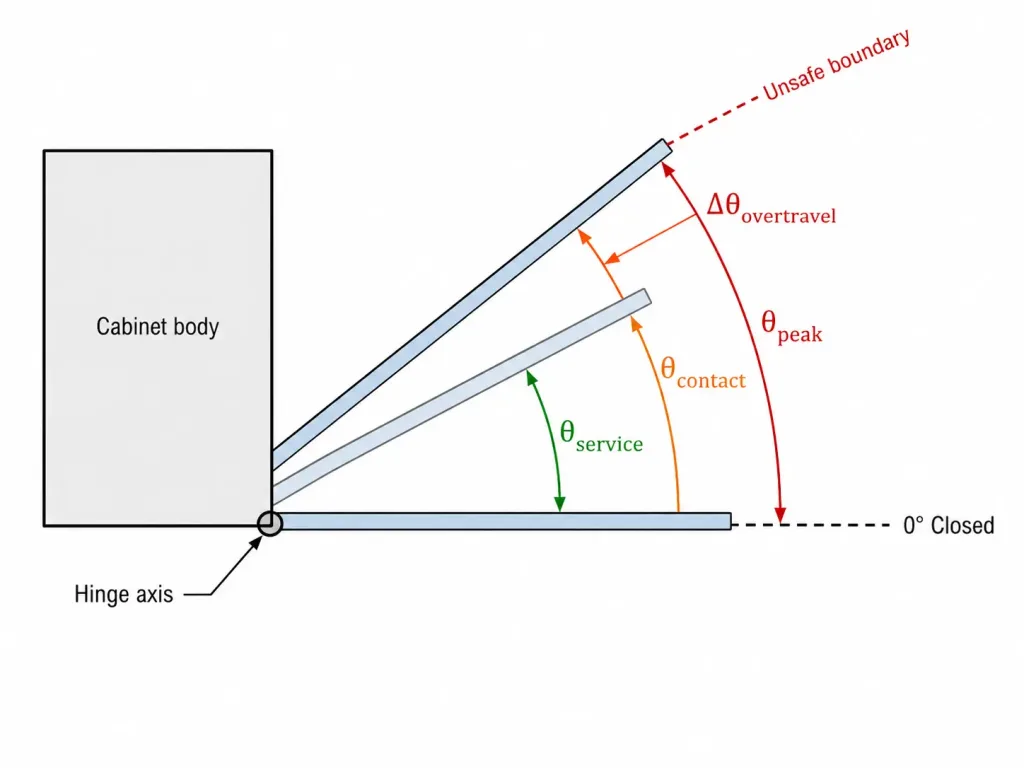
The second boundary comes from the opposite direction. Trace the door farther open until the first unacceptable condition occurs. That may be contact with another machine, excessive cable bend, a handle entering an aisle, an unsafe pinch geometry, a door-mounted device hitting the frame, or insufficient remaining clearance to another moving assembly.
This becomes the maximum safe angle. The opening-stop system has to operate between those two boundaries with enough margin for manufacturing tolerance, structural compliance and movement after first contact.
| Angle Input | What It Represents | Where It Should Come From |
|---|---|---|
| Minimum service angle | Smallest opening that allows the intended task | Equipment layout, maintenance task or removal path |
| Nominal stop-contact angle | Target angle at which the designated stop first engages | Door-system specification and stop geometry |
| Stop-contact tolerance | Production variation in the first-contact position | Door, frame, stop and mounting tolerances |
| Overtravel | Additional angular movement after first stop contact | Stop compliance, joint movement and validation |
| Peak opening angle | Maximum transient angle reached during the stopping event | Stop contact plus actual overtravel under load |
| Maximum safe angle | Earliest unacceptable door position | Complete assembly and surrounding equipment |
There must be room for real manufacturing variation between the required service position and the first unsafe position. If the design only works at one mathematically exact angle, there is no useful tolerance budget for the stop.
Put the Angle on a Real Datum
“Stops at 110°” is incomplete unless everyone measures 110° from the same geometry.
Define the fixed reference surface, moving reference surface, hinge axis and direction of rotation on the assembly drawing. Closed can be called 0° when the closed position itself is repeatable, but that assumption deserves checking on doors pulled against compressible gaskets or adjustable latches.
Also separate the hinge mechanism angle from the finished door angle. Brackets, offsets, formed door returns and multi-link concealed mechanisms can make a catalog angle a poor substitute for the position of the actual panel.
For concealed mechanisms, trace the complete moving envelope before setting the stop. The door can encounter the frame at an intermediate angle even though the hinge itself still has travel available. The detailed geometry belongs in the concealed hinge cutout and clearance guide; the stop specification should use the resulting allowable motion rather than repeat the cutout analysis here.
Drawing note: show the angular reference in the same assembly view that identifies the hinge axis and stop contact. A standalone “110° max” note leaves too much room for different interpretations.
Do Not Make Hinge End Travel the Default Stop
A hinge may have a maximum geometric travel without being designed to absorb repeated opening impacts at that limit.
Those are two different requirements. One describes how far the mechanism can rotate. The other describes what happens when a moving door must be brought to zero speed.
If an internal pin, link, leaf edge or concealed-hinge feature becomes the first hard contact, the stop reaction travels through the hinge structure and its mounting joint. The result may be leaf deformation, loosened fasteners, elongated holes, pin damage, bracket movement or a gradual shift in door alignment even when the hinge carries the static door weight comfortably.
An integrated stop is entirely valid when the hinge is intentionally designed for that function and its allowable stopping condition is documented for the intended configuration. Without that evidence, treat the hinge’s geometric limit as a motion boundary—not as an impact-load rating.
Stop, Hold-Open and Damping Are Different Jobs
Industrial door specifications often use “stop” for several different behaviors. That creates trouble when a supplier solves one function and the assembly needed another.
| Function | What It Does | What It Does Not Automatically Do |
|---|---|---|
| Opening stop | Limits maximum angular travel | Hold the door open or control approach speed |
| Hold-open device | Resists movement away from an open position | Absorb a high-energy impact unless specifically designed to do so |
| Damper / backcheck | Reduces opening speed or dissipates energy | Provide a structural final stop unless that function is included |
| Detent | Creates a preferred indexed position | Define maximum allowable travel |
| Torque hinge | Provides rotational resistance or position holding | Serve as an impact stop without a rated stop feature |
A mechanism may combine two or more functions, but the specification should still name them separately. For example, a door check can slow the final portion of opening and then reach a structural limit. A torque hinge can hold the panel during service while a separate bracket establishes maximum travel.
That distinction matters because reducing approach speed can substantially reduce the energy reaching the final stop, while merely adding a stronger stop does nothing to reduce the door’s incoming speed.
Impact Load Begins With Door Energy
Static door load and opening-stop impact should not be treated as the same calculation.
A side-hinged door rotating about its hinge axis has rotational kinetic energy immediately before the stop engages. For a preliminary engineering estimate:
Ek = 1/2 Iω²
where:
Ek = rotational kinetic energy, J
I = mass moment of inertia about the hinge axis, kg·m²
ω = angular velocity immediately before stop contact, rad/s
For a thin, approximately uniform rectangular door rotating about one vertical edge, a preliminary inertia estimate is:
I ≈ (1/3)mb²
where:
m = complete moving door mass, kg
b = door width measured perpendicular to the hinge axis, m
Use CAD mass properties when the door includes heavy windows, handles, insulation, lock rods, displays or other components that shift the mass distribution. If the actual hinge axis is offset from the assumed door edge, use the mass moment of inertia about the actual rotation axis rather than relying on the simplified rectangular-door equation.
If the stop absorbs the incoming kinetic-energy term through an effective angular stopping movement Δθ, the corresponding average resisting torque can be approximated as:
Tavg ≈ Ek / Δθ
If the stop contact acts at an effective perpendicular radius r from the hinge axis:
Favg ≈ Tavg / r
These equations are useful for understanding the design variables. They do not create a universal stop rating. Real peak force depends on the stiffness and damping of the bumper, bracket, door, frame and contact surfaces, as well as the actual velocity profile.
The energy estimate above only represents the incoming kinetic-energy term. If an operator, spring, actuator or other driving source continues doing positive work after stop contact, that additional work must also be included in the energy the stop system has to dissipate.
A person can keep pushing after first contact. A spring can continue supplying torque. A powered actuator may remain energized. Wind can accelerate an exposed panel. An installation that is not level can introduce another driving moment. Those inputs need to be included when they exist.
A small change in stopping travel changes the reaction
Consider an illustrative 25 kg door with an approximately uniform 0.8 m width. Using the simplified rectangular-door model gives an inertia of about 5.3 kg·m². If it reaches 1.5 rad/s before contact, its rotational kinetic energy is about 6 J.
If that energy were dissipated over 0.02 rad of effective stopping movement, the energy-based average resisting torque would be roughly 300 N·m. Reduce the stopping movement to 0.005 rad, and the corresponding average rises to roughly 1,200 N·m before any peak-force effect or continued operator input is considered.
The lesson is not that either value is a production design load. The lesson is that a nearly rigid stop and a controlled-energy stop can produce very different structural demands even though both limit the door at almost the same visible angle.
This is an illustrative engineering scenario, not a customer project record or product test claim.
Stop Radius Changes the Contact Force
The location of the stop is part of the load calculation.
For the same required resisting torque, a stop acting close to the hinge axis sees a larger contact force than one acting farther away. Moving the contact outward can therefore reduce local force, but only when the door and frame at that location are stiff enough to carry the reaction.
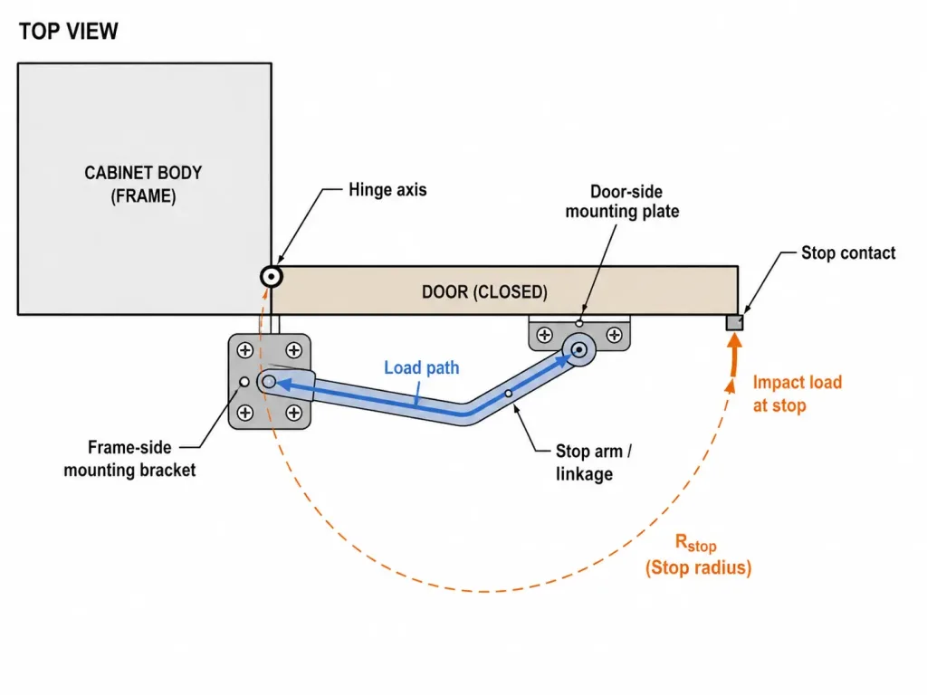
This creates a real engineering conflict. A compact stop tucked beside the hinge can look mechanically neat and remain protected from accidental contact, yet its short moment arm can create a high local reaction. A stop positioned farther toward the free edge reduces the force for the same resisting moment but may require substantial door-edge reinforcement and can occupy service space.
The contact direction matters as well. A stop that drives mostly into a supported compression path is normally easier to manage than one that pries a thin flange away from the door or bends a small bracket sideways.
Do not optimize stop radius by itself. The useful position is the one that produces an acceptable combination of moment arm, local stiffness, contact geometry, packaging and service access.
Overtravel Starts After First Contact
First contact is not necessarily the maximum angle reached by the door.
An elastomer bumper compresses. A cable or restraint stretches. A formed bracket bends. Thin sheet metal deflects. Fastened joints can move. Hinge clearance can contribute a small additional rotation. Several of these movements may occur at the same time.
In this article, overtravel means the additional angular movement that occurs after the designated stop first makes contact. The maximum transient angle reached during that event is the peak opening angle.
That distinction matters because the door can momentarily move beyond the static angle visible after rebound. A door that returns to a safe position after impact may still have crossed into an interference zone during the stopping event.
| Overtravel Source | What Changes the Value | What to Define or Measure |
|---|---|---|
| Bumper compression | Material, geometry, temperature, aging and contact force | Compression or angular movement under the relevant load |
| Bracket deflection | Section thickness, unsupported length and load direction | Elastic movement and permanent set |
| Door/frame flex | Panel construction and reinforcement | Relative movement at stop contact |
| Tether extension | Length, construction, fittings and pretension | Loaded extension and attachment movement |
| Hinge and joint clearance | Pin fit, mounting clearance and wear | Angular contribution at the door |
| Fastener or joint movement | Clamp load, slots, substrate stiffness and repeated impact | Slip, witness-mark movement or permanent displacement |
The angular stack should protect both sides of the usable window. At the low-angle tolerance extreme, first stop contact must still occur late enough to provide the required service opening. At the high-angle extreme, first contact plus the maximum expected overtravel must remain below the earliest unsafe position.
θservice, required ≤ θcontact, min
θpeak = θcontact + Δθovertravel
θcontact, max + Δθovertravel, max < θunsafe, min
The variables are project-specific. There is no responsible universal number of degrees that can simply be added to every industrial door as an “overtravel safety factor.”
Build the Structural Load Path First
A strong-looking bumper attached to weak sheet metal is not a strong opening stop.
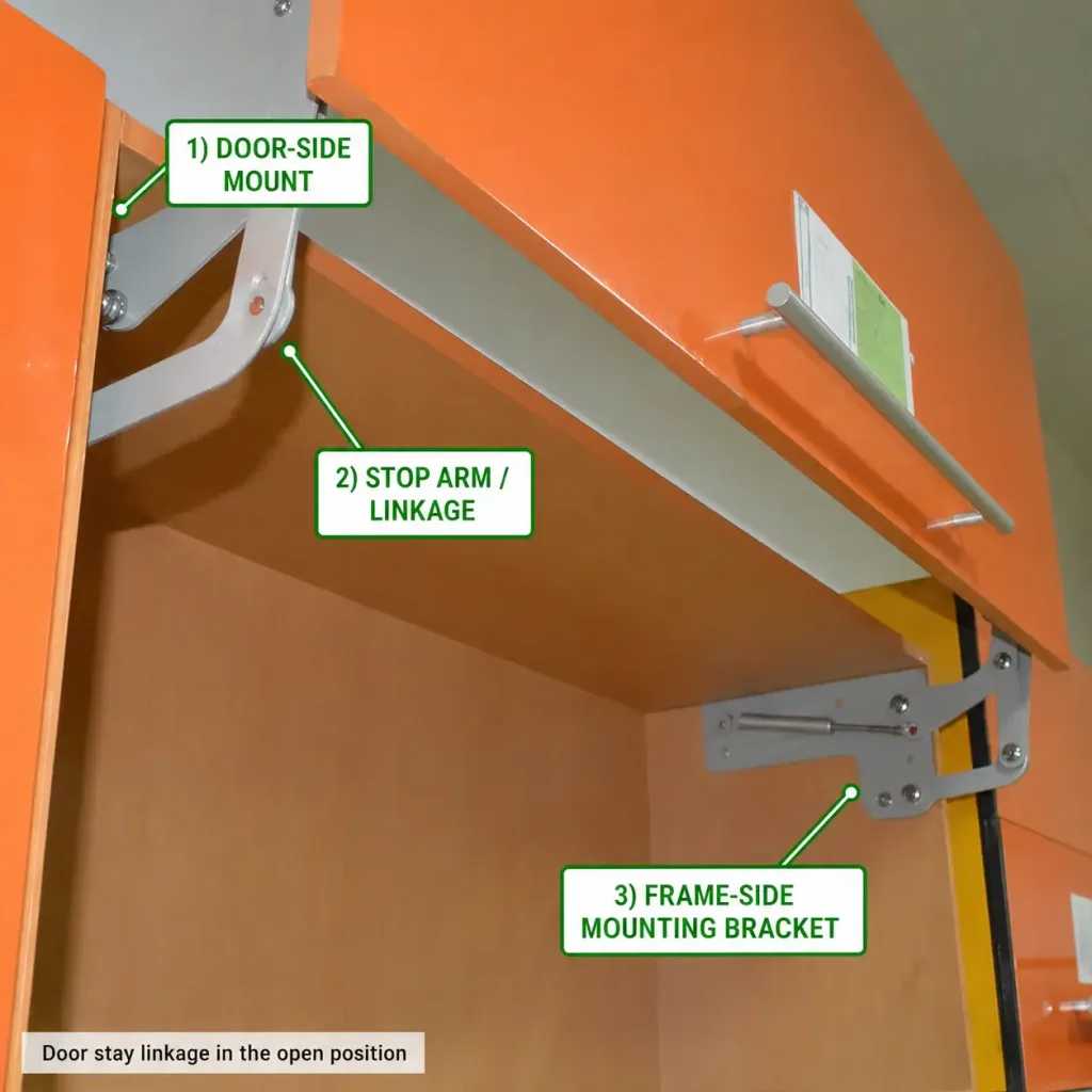
In the hinge application engineering review, follow the reaction from the contact point through every interface until it reaches structure capable of resisting it:
- stop contact or bumper;
- stop bracket or arm;
- door reinforcement or structural member;
- fasteners, welds or formed joint;
- frame reinforcement;
- equipment structure.
Both sides of the contact need a load path. Reinforcing the frame-side stop while leaving the door-side strike on an unsupported skin only moves the weak point.
This is also why a cable harness, bonding strap, gasket, latch rod or interlock bracket should never become the accidental maximum-opening device. Those components have their own jobs, and their attachment points may not be designed for repeated opening impacts.
Where the stop reaction enters thin sheet metal, the detailed fastener, insert and reinforcement design should be reviewed separately. The thin sheet-metal hinge mounting guide explains how local panel stiffness and reinforcement change the joint load path.
Two Stops Do Not Automatically Share the Load
A wide industrial door may appear to benefit from two stop contacts. Do not automatically divide the calculated reaction by two.
If one bumper sits slightly proud, one bracket is stiffer, the door twists, or the frame has accumulated fabrication error, the first contact may take most of the initial event. The second stop may engage only after the structure has already deflected.
True load sharing depends on contact-position tolerance, stiffness, door torsional rigidity and how the stop surfaces engage under load. If the design requires both stops to share the reaction, that behavior needs to be demonstrated rather than assumed from symmetry on the CAD model.
The same warning applies to multiple hinges. Adding another hinge does not automatically turn the hinge set into a suitable multi-point opening stop.
The Opening Condition Belongs in the Specification
A stop cannot be reviewed properly from the final static angle alone. The supplier or equipment engineer needs to know how the door arrives at the stop.
At minimum, define whether the door is hand-operated, spring-driven, actuator-driven or exposed to an external condition that can accelerate it. Include the complete moving mass and mass distribution, expected approach speed when known, the stop location, available stopping movement and the structure behind both contact surfaces.
For a self-closing or spring-loaded door, also consider stored spring energy and the force profile through the travel. For powered doors, the control logic and actuator behavior at the end of travel matter. A motor that continues producing torque after stop contact creates a different event from a manually moved door that is released before contact.
For machine guards, the opening-stop specification does not replace the guarding risk assessment, interlock design or safety-related control function. Those application-specific boundaries are covered in the machine guard hinge guide.
What the Drawing Should Actually Control
Once the geometry and stopping condition have been established, convert them into fields that another engineer, supplier and inspector can interpret the same way.
| Specification Field | Required Definition | Why It Matters |
|---|---|---|
| Door angle datum | Fixed surface, moving surface, hinge axis and rotation direction | Prevents different angle interpretations |
| Required service angle | Minimum usable opening of the finished assembly | Protects maintenance and operating access |
| Nominal stop-contact angle | Target angle at which the designated stop first engages | Separates first contact from subsequent overtravel |
| Stop-contact tolerance | Allowed production range for first contact | Accounts for real assembly variation |
| Maximum safe angle | Earliest unacceptable door position | Creates the upper boundary for contact tolerance plus overtravel |
| Maximum permitted overtravel | Allowed additional movement after first contact under the defined event | Protects adjacent components during the stop event |
| Maximum permitted peak angle | Highest transient door angle during stopping | Controls the true interference boundary rather than rebound position |
| Stop architecture | Hard stop, cushioned stop, restraint, check arm or rated integrated stop | Defines how travel is arrested |
| Contact location | Position relative to hinge axis and structural datums | Controls moment arm and local reaction |
| Opening condition | Manual, spring, actuator, wind or other driving input | Defines the energy source |
| Door mass properties | Complete moving mass and relevant mass distribution | Supports energy and structural review |
| Structural interface | Door and frame reinforcement, fastening or weld arrangement | Defines the reaction path |
| Acceptance condition | Peak angle, permanent set, deformation, loosening and functional change | Makes prototype validation measurable |
If the opening stop is integrated into the hinge, add the exact hinge part number and revision and request the stop condition that applies to that configuration. Do not transfer an opening-angle statement from a similar hinge and assume it carries the same dynamic stop capability.
The broader rules for controlled dimensions, drawing revisions, tolerances and performance evidence are covered in how to read a hinge spec sheet and engineering drawing.
A Practical Stop Specification Block
A supplier does not need a long project-management form. It does need the variables that control the stop.
INDUSTRIAL DOOR OPENING-STOP REQUIREMENT

Application / equipment:
Door orientation:
Door opening direction:

ANGLE
Angle reference / datum:
Minimum required service angle:
Nominal stop-contact angle:
Permitted stop-contact tolerance:
Maximum safe door angle:
Maximum permitted overtravel after first contact:
Maximum permitted peak opening angle:

MOVING ASSEMBLY
Complete moving mass:
Mass properties / CG information:
Opening method: manual / spring / actuator / other
Expected approach speed or operating condition:
Additional driving torque after contact, if applicable:

STOP INTERFACE
Stop type / proposed architecture:
Distance from hinge axis to stop contact:
Door-side contact construction:
Frame-side contact construction:
Bumper / compliant element, if any:
Available stopping movement:

STRUCTURE
Door reinforcement at stop:
Frame reinforcement at stop:
Fastener / weld arrangement:

VALIDATION
Test opening condition:
Number of impact events or project duty:
Maximum permitted peak opening angle during stop event:
Maximum permitted permanent angular set after testing:
Maximum permitted permanent structural deformation:
Fastener / weld acceptance:
Required post-test door, hinge, latch and cable function:
Fields that are not yet known can remain project-specific during early design, but the unknown should be visible. Replacing missing data with a generic “heavy duty” stop rating does not make the requirement more complete.
Validate the Complete Door, Not the Stop Alone
A bench test can prove that a bumper, bracket or hinge feature survives one fixture condition. It cannot by itself prove that the finished equipment will remain inside its allowable opening envelope without damaging nearby systems.
Prototype validation should use production-intent door mass, hinge locations, reinforcement, stop hardware and surrounding components wherever practical. Reproduce the relevant opening condition rather than gently guiding the door into contact when the real equipment will reach the stop at speed.
Record the baseline before testing. Useful observations include the first stop-contact angle, door gaps, stop-bracket position, fastener witness marks, hinge play, cable clearance and latch alignment.
During the stopping event, measure or otherwise capture the peak opening angle when the safety margin depends on overtravel. Checking only the final rebound position can miss a transient interference condition.
After the defined opening events, inspect for:
- permanent movement of the stop or strike;
- cracks around welds, bends or mounting holes;
- fastener slip or loosening;
- local panel buckling or permanent set;
- changed hinge play or door sag;
- bumper tearing, extrusion or excessive compression set where relevant;
- increased first-contact or peak opening angle;
- contact with cables, hoses, latches or neighboring equipment;
- loss of normal door closing and latching behavior.
If impact performance matters, record opening speed or another reproducible input. “Opened firmly by hand” is difficult to repeat between engineers, suppliers and production audits.
Acceptance should describe the whole assembly after the event. A stop that remains unbroken but allows an unsafe transient angle, permanently shifts the door, loosens the mounting surface or changes cable clearance has not necessarily protected the system.
When the Stop Should Be Separate From the Hinge
A separate structural stop is usually the clearer architecture when the door is heavy, approach speed is significant, stop loads need to enter reinforced structure away from the hinge, or the selected hinge has no documented opening-stop capability.
An integrated hinge stop becomes attractive when packaging is tight, the required stop function is intentionally part of the hinge design, and the supplier can define how that function is rated or validated for the proposed configuration. The choice should come from the load path and evidence, not from the desire to remove one visible component.
If the project is still deciding whether the door needs a concealed, removable, spring, torque, weld-on or standard load-carrying hinge, settle that motion requirement first using the industrial hinge selection guide. Opening-stop design comes after the basic door motion architecture is understood.
A complete industrial door opening stop specification should ultimately answer five questions: where the door must open for service, where the designated stop first contacts, how much movement can occur after contact, how the stopping load enters the structure, and how the peak opening condition will be verified on the finished assembly.
Industrial Door Opening Stop Questions
Is the hinge maximum opening angle the same as the door stop angle?
No. A hinge maximum opening angle describes mechanism travel. The finished door stop should be specified from the required service opening, the designated first-contact angle, expected overtravel and the maximum safe angle of the complete assembly.
How do you calculate impact load on an industrial door stop?
Start with the rotational energy of the complete moving door and the effective stopping movement, then convert the required resisting torque to contact force using the stop moment arm. Include additional work from an operator, spring or actuator when it continues applying force after stop contact. The result is still a preliminary engineering estimate because peak force depends on stiffness, damping and contact behavior.
How much overtravel should an industrial door stop allow?
There is no universal overtravel angle. It depends on bumper compression, restraint extension, bracket and panel deflection, hinge clearance, joint movement and the energy of the stopping event. The maximum stop-contact angle plus worst-case overtravel must remain below the first unsafe door position.
Why is peak opening angle different from the final door angle?
A compliant stop, flexible bracket or moving joint can let the door travel beyond the first-contact angle and then rebound. The door may therefore finish at a safe static angle even though it briefly crossed an interference boundary during impact. Critical assemblies should control the peak transient opening angle, not only the final rebound position.
Can the hinge itself be used as the opening stop?
Only when the hinge is intentionally designed for that function and the supplier provides suitable evidence for the required configuration and stopping condition. A geometric maximum opening angle alone should not be treated as an impact-load rating.
Review the Door Stop Interface Before Sampling
Send the door layout, hinge axis, moving-door mass, required service angle, maximum safe angle and proposed stop location. These inputs help define the opening-stop requirement before hinge selection or sample evaluation.
Send Your Door Layout