-
+86 13720060320
-
lanna@haitangs.com

How to Read a Hinge Spec Sheet and Engineering Drawing
A hinge spec sheet can look complete because it shows a product image, several dimensions, a material name, and a load or torque value. An engineering drawing can look even more authoritative because it includes views, tolerances, symbols, and a revision block. Neither document is useful, however, unless the reader can tell exactly what is controlled, what is only descriptive, what remains unconfirmed, and which performance claims depend on separate test conditions.
This guide explains how engineers, OEM buyers, quality teams, and project managers should read a hinge specification sheet and supplier drawing before approving a sample or production order. It begins after the hinge family has already been selected. If the project still needs to decide between torque, concealed, lift-off, weld-on, spring, or standard hinges, start with our guide on how to choose an industrial hinge.
Quick answer: Read a hinge drawing in this order: document identity and revision, units and projection, product configuration, overall envelope, mounting-hole pattern, individual and general tolerances, material and finish, functional requirements, load or torque test conditions, and approval status. Never approve a hinge from one attractive dimension or a single “maximum load” value. The drawing, spec sheet, test evidence, and approved sample must describe the same part and revision.
Spec Sheet, Drawing, Test Report, and Sample: Four Different Types of Evidence
Industrial hinge projects often fail because four different documents are treated as if they prove the same thing. They do not.
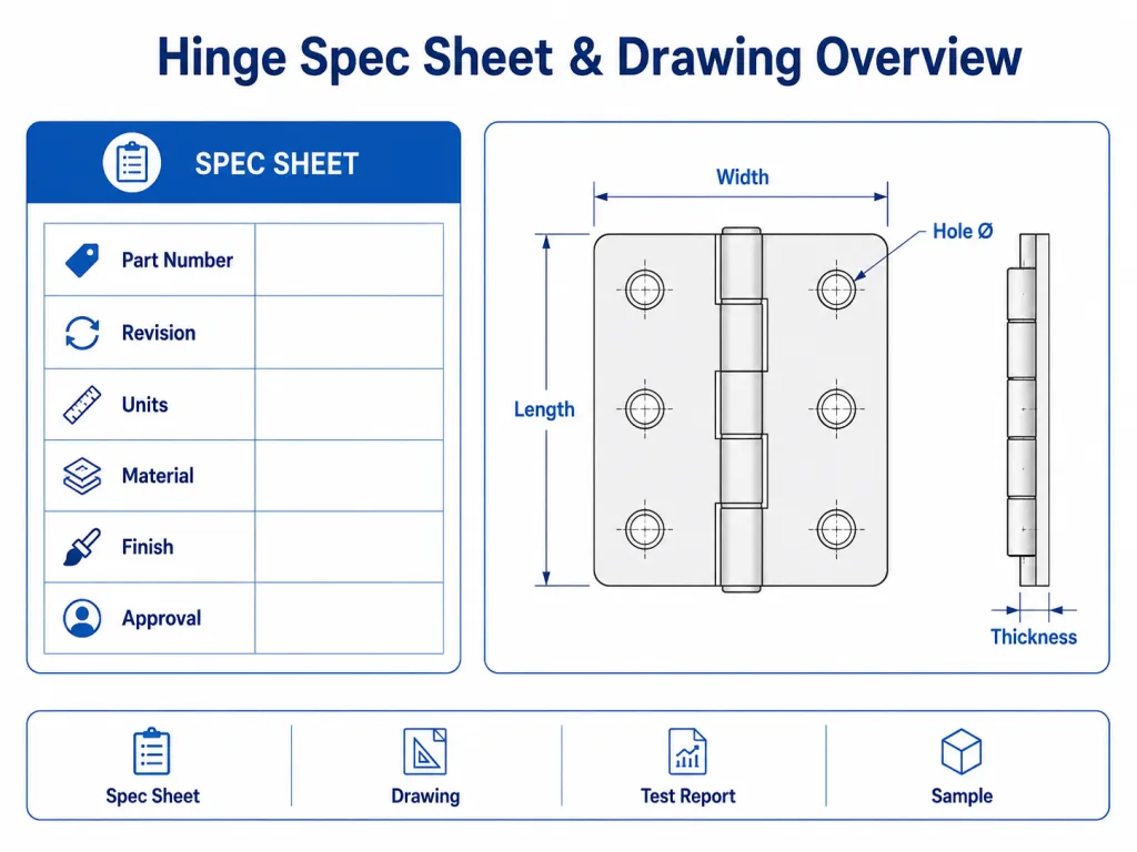
| Document or Evidence | What It Should Define | What It Does Not Prove by Itself |
|---|---|---|
| Product spec sheet | Product family, key dimensions, material, finish, function, nominal performance, available options | Every manufacturing dimension, all tolerances, or order-specific compliance |
| Engineering drawing | Controlled geometry, hole pattern, dimensions, tolerances, material notes, orientation, revision | Real cycle life, corrosion performance, user feel, or installed-system suitability unless test requirements are included |
| Test report | Test method, sample identification, fixture, conditions, measurements, and results | That every future production lot matches the tested sample |
| Approved sample | Physical fit, movement, surface appearance, assembly behavior, and reference feel | Hidden material grade, all dimensions, long-term life, or repeatable production control without supporting records |
The four should support one another in inspection and test verification. A sample that feels correct but does not match the approved drawing is not a stable production reference. A drawing with a torque value but no torque test method leaves room for different interpretations. A material certificate for SUS 304 does not confirm that the dimensions or finish match the order.
1. Start With Document Control, Not the Dimensions
Before reading the hinge geometry, confirm that the document itself can be identified and controlled. Many costly mistakes come from approving the correct design on the wrong revision.
| Title-Block Field | What to Check | Why It Matters |
|---|---|---|
| Part number | Exact supplier and customer part number | Similar hinge models may differ only in torque, handing, pin direction, or finish |
| Drawing number | Controlled document identifier | The drawing number may differ from the commercial model number |
| Revision | Revision letter or number and change description | A changed hole pattern or material may not be visible in a filename |
| Date | Issue and revision date | Helps identify whether the quotation uses the latest document |
| Status | Preliminary, for quotation, for sample, approved, or released | A quotation drawing should not automatically become a production drawing |
| Units | Millimeters, inches, degrees, N·m, N·cm, lbf·in, or other units | A unit assumption can create a major fit or performance error |
| Scale | Drawing scale and “do not scale” note | Dimensions must come from stated values, not measurements taken from a PDF image |
| Projection method | First-angle or third-angle projection symbol | Changes how the reader interprets the relationship between views |
| Applicable drawing standard | Company standard, ASME, ISO GPS, or project standard | Controls how symbols, tolerances, and defaults are interpreted |
If the supplier revises the drawing, require a revision summary. “Updated drawing attached” is not enough. The reviewer should know whether the change affects fit, function, material, tooling, inspection, or interchangeability.
2. Identify the Exact Hinge Configuration
A drawing may show the correct outer shape while leaving the functional configuration unclear. Confirm the product type and every option that changes installation or movement.
- Standard free-swinging, torque, spring, detent, concealed, weld-on, lift-off, or swivel hinge
- Left-hand, right-hand, reversible, or non-handed configuration
- Clockwise, counterclockwise, one-way, or two-way torque resistance
- Door leaf and frame leaf assignment
- Pin direction and removal direction for lift-off hinges
- Opening stop, detent angles, or full rotation
- With or without bushings, washers, seals, covers, or mounting hardware
- Standard model, modified standard model, or fully custom part
Do not assume that two hinges with the same overall dimensions are interchangeable. A hidden stop, different pin retention, reversed handing, or different torque direction can make the part unsuitable even when every mounting hole aligns.
3. Read the Views Before Reading the Numbers
Engineering drawings use multiple views because one view cannot communicate every feature. Before following dimension lines, identify what each view represents.
| View Type | What It Usually Shows on a Hinge |
|---|---|
| Front or plan view | Leaf outline, hole pattern, overall length and width |
| Side view | Leaf thickness, knuckle diameter, offsets, bends, mounting height |
| End view | Pin position, barrel alignment, bracket shape, open or closed profile |
| Section view | Pin, bushing, washers, friction stack, spring, or concealed internal parts |
| Detail view | Small features such as staking, countersinks, slots, grooves, or retention screws |
| Exploded view | Component order and assembly relationship |
| Alternate-position view | Open angle, closed angle, stop position, or movement envelope |
Check whether the shown position is open, closed, unloaded, or installed. A concealed hinge may have very different envelope dimensions when open. A torque hinge drawing may show the shaft center but not the clearance needed by the moving panel. A lift-off drawing may show the assembled height but not the required disengagement travel.
4. Check the Overall Envelope and Installation Space
Overall length and width are only the beginning. The hinge must fit in both its static and moving conditions.
- Overall leaf length and width
- Closed thickness or mounting height
- Knuckle, barrel, or housing diameter
- Pin-head, screw-head, and washer projection
- Offset between the hinge axis and mounting plane
- Required recess or cutout for concealed hinges
- Moving envelope through the full opening range
- Tool access for screws, adjustment, retention, or removal
- Cable, hose, gasket, and adjacent-component clearance
Use the assembly drawing to verify the hinge envelope against the real door and frame. A supplier drawing can prove the hinge dimensions, but it cannot prove there is enough space inside your cabinet, machine cover, display, or access panel unless both drawings are considered in a drawing and mounting interface review.
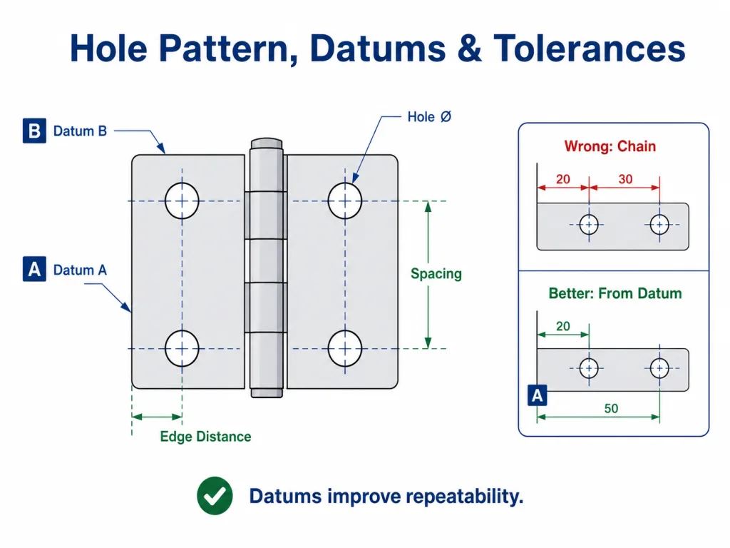
5. Read the Mounting-Hole Pattern From a Datum
Hole patterns are where apparently minor drawing differences become assembly failures. Do not check only the hole diameter. Read the entire mounting definition.
| Hole-Pattern Feature | Questions to Ask |
|---|---|
| Hole diameter | Clearance, threaded, reamed, or press-fit? What fastener is intended? |
| Center-to-center spacing | Is the pattern controlled from a common datum or chained from hole to hole? |
| Edge distance | Is there enough material between the hole and leaf edge to prevent deformation? |
| Slot size and direction | Does the slot permit adjustment in the direction the assembly actually needs? |
| Countersink | Included angle, major diameter, depth, and intended screw-head style? |
| Counterbore | Diameter and depth sufficient for the fastener head and tool? |
| Thread | Thread standard, nominal size, pitch, class, and minimum engagement? |
| Pattern position | How is the complete pattern located relative to the hinge axis and mounting edge? |
A hole pattern defined by chained dimensions can accumulate variation. For critical alignment, the drawing should make clear which surfaces, edges, or axes act as datums. This is especially important when multiple hinges must share one axis or when the latch and gasket depend on repeatable door position.
6. Separate Nominal Dimensions From Tolerances
A nominal dimension describes the intended size. The tolerance defines the acceptable variation. A dimension without a visible plus/minus value may still be controlled by a general tolerance note in the title block.
| Tolerance Format | Example | Meaning |
|---|---|---|
| Symmetrical | 20.0 ± 0.2 mm | Acceptable range is 19.8 to 20.2 mm |
| Unilateral | 20.0 +0.2 / -0.0 mm | The feature may be larger but not smaller than nominal |
| Limit dimensions | 19.8–20.2 mm | Minimum and maximum are stated directly |
| Angular | 90° ± 1° | Controls bend, leaf, stop, or bracket angle |
| General tolerance | ISO 2768 class or company note | Applies where an individual tolerance is not shown, subject to the stated scope |
| Reference dimension | (20.0) or REF | Usually informational and not an independent acceptance requirement |
Read the general tolerance note carefully. ISO 2768 is commonly used to simplify tolerance indications for dimensions without individual tolerances, but the applicable part, class, process scope, and project requirements still need to be clear. An individually stated tolerance normally takes precedence over the general note. The current supplier drawing should identify the exact standard or internal tolerance table used. ISO’s official description of ISO 2768 explains that the standard is intended to simplify drawing indications by defining general tolerance classes.
Tighter is not automatically better. An unnecessarily tight tolerance can increase machining, stamping, tooling, and inspection cost without improving hinge function. The reviewer should ask which dimensions actually control fit, alignment, motion, sealing, or interchangeability.
7. Understand the GD&T Controls That Matter Most for Hinges
Geometric dimensioning and tolerancing controls shape, orientation, and location—not only feature size. ASME Y14.5 is a widely used dimensioning and tolerancing standard, while ISO 1101 defines the ISO GPS symbol language and interpretation rules for geometrical specification. The drawing should state which system applies because similar-looking drawings may follow different default rules. ASME describes Y14.5 as the authoritative guideline for GD&T design language, and ISO 1101 defines the symbol language for geometrical specification.
| Control | Why It May Matter on a Hinge |
|---|---|
| Datum | Creates the reference framework for hole patterns, hinge axis, and mounting surfaces |
| Position | Controls the location of holes or a hole pattern relative to datums |
| Flatness | Helps mounting leaves seat without rocking or twisting |
| Parallelism | Can control opposing mounting surfaces, leaves, or related axes |
| Perpendicularity | May control brackets, mounting faces, or pin orientation |
| Profile | Can control formed, cast, or complex leaf and bracket shapes |
| Runout | May be relevant to rotating shafts, swivel components, or cylindrical features |
Do not interpret a GD&T frame from the symbol alone. Read the tolerance value, referenced datums, material-condition modifiers where present, and the feature to which the frame is attached. For a multi-hole pattern, position relative to stable datums is usually more useful than checking each center-to-center dimension independently.
8. Read Material at the Component Level
“Stainless steel hinge” is not a complete material specification. A hinge may contain different materials in the leaves, pin, bushing, friction washers, spring, fasteners, and cover.
| Component | Material Information to Confirm |
|---|---|
| Leaves or body | Exact alloy or grade, thickness, casting or forming basis |
| Pin or shaft | Grade, hardness, surface treatment, retention method |
| Bushing or bearing | Polymer, bronze, steel, or other material; lubrication requirement |
| Friction elements | Material family, temperature suitability, compression behavior |
| Spring | Material, heat treatment, direction, preload where controlled |
| Fasteners | Material, grade, coating, thread, and whether included |
When the drawing calls out SUS 304 or SUS 316, confirm which components use that grade. Do not assume that a 316 leaf means the pin and screws are also 316. For a more detailed environmental comparison, see our guide to SUS 304 vs SUS 316 hinges.
For critical orders, material grade should be supported by the agreed certificate or inspection record. The drawing defines the requirement; the material document supports the production lot.
9. Treat Finish as a Controlled Requirement
Surface finish affects appearance, corrosion resistance, friction, fit, electrical continuity, and installation. “Black,” “zinc plated,” or “passivated” may be too vague for an approval drawing.
- Finish type and applicable process specification
- Coating or plating thickness where functionally important
- Color, gloss, and texture reference for visible parts
- Passivation or post-treatment requirement
- Masking areas around threads, grounding points, bearings, or friction surfaces
- Acceptance limit for scratches, stains, color variation, or exposed base metal
- Whether dimensions apply before or after coating
Coating buildup can reduce hole clearance, change countersink fit, affect concealed-hinge pockets, or create binding at the knuckle. The drawing should make clear which critical dimensions apply to the finished part.
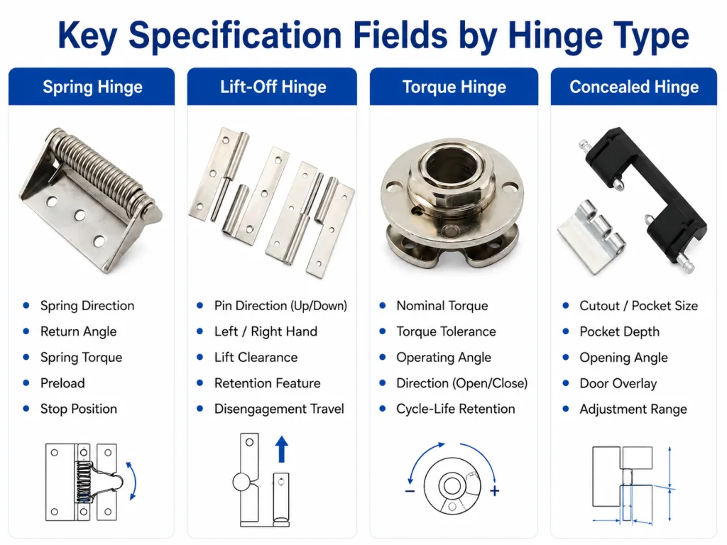
10. Read the Functional Specification for the Hinge Type
The geometry tells you whether the hinge can fit. The functional specification tells you whether it can do the required job. Different hinge families need different performance fields.
| Hinge Type | Functional Fields to Look For |
|---|---|
| Standard hinge | Opening range, pin retention, bearing or bushing, free movement, allowable play |
| Torque or friction hinge | Nominal torque, tolerance, direction, breakaway torque, operating angle, temperature, cycle-life retention |
| Adjustable torque hinge | Adjustment range, adjustment method, locking method, measurement condition |
| Spring hinge | Closing or opening direction, spring torque, preload, working angle, return position |
| Detent hinge | Detent angles, engagement force, release force, angular tolerance |
| Lift-off hinge | Pin direction, handing, disengagement travel, anti-lift retention, door and frame leaf |
| Concealed hinge | Cutout, pocket depth, opening angle, interference envelope, adjustment range |
| Weld-on hinge | Weld location, material compatibility, pin protection, post-weld alignment |
| Swivel hinge | Rotation range, axial and radial load, torque, runout, cable-routing diameter |
A torque value without direction and measurement condition is incomplete. A spring description without preload direction is incomplete. A lift-off drawing without the removal vector is incomplete. Functional fields must describe how the exact configuration behaves, not only what the product family is called.
11. Do Not Read a Load Rating Without Its Test Conditions
“Maximum load: 50 kg” may look decisive, but it is not an engineering approval basis unless the test arrangement is known. Door weight alone does not describe the moment, installation stiffness, or load distribution.
| Load-Rating Question | Why It Changes the Result |
|---|---|
| How many hinges were tested? | One, two, and three hinges do not necessarily share load equally |
| What was the hinge spacing? | Spacing affects door stability and load distribution |
| What was the load direction? | Radial, axial, tensile, shear, and moment loads stress different features |
| What was the door width or lever arm? | A wider door creates more moment at the hinge axis |
| What mounting substrate was used? | Rigid steel plate and thin sheet metal do not behave the same way |
| Which fasteners were used? | Fastener size, engagement, and backing can control the failure mode |
| Static or cyclic test? | A static survival test does not prove repeated-use durability |
| What acceptance criterion applied? | No fracture is different from no permanent deformation or no door sag |
| Was a safety factor included? | Catalog “maximum” and recommended working load may not be the same |
If the supplier cannot provide full test conditions, treat the value as preliminary catalog information. Final approval should use the real door, hinge spacing, mounting structure, and operating environment or a representative validated fixture.
12. Read Torque and Cycle-Life Data Together
For torque hinges, initial torque is only one point in the specification. The more useful document defines how torque is measured and how much may change during use.
- Nominal torque per hinge
- Allowed torque tolerance
- Opening and closing direction
- Breakaway torque versus running torque
- Measurement angle and speed
- Temperature and conditioning before measurement
- Number of cycles
- Torque-retention requirement after cycling
- Permitted noise, sticking, play, or drift
Do not compare torque numbers from two suppliers unless the unit, direction, angle, speed, temperature, and test method are comparable. A higher catalog number is not automatically better; excessive torque can increase user effort and damage the mounting structure.
13. Check the Environmental Requirement and Acceptance Criteria
A drawing may specify material and finish while the spec sheet lists temperature, humidity, salt spray, cleaning chemicals, UV, dust, or washdown exposure. Confirm whether these are design targets, tested conditions, or general marketing claims.
For salt-spray references, the test standard alone is not enough. ASTM B117 describes the apparatus, procedure, and conditions for a controlled salt-fog environment, but it does not by itself define the product-specific exposure duration or how results should be accepted. The requirement should also state hours, specimen condition, protected or scribed surfaces where relevant, allowable corrosion, and whether the hinge must still move or separate after testing. ASTM also cautions that standalone salt-spray results do not reliably predict natural-environment performance. See ASTM’s official B117 scope and limitations.
| Environmental Field | What a Reviewable Specification Should State |
|---|---|
| Operating temperature | Minimum, maximum, and whether function must be measured at those temperatures |
| Corrosion test | Method, duration, preparation, acceptance criteria, and post-test function |
| Cleaning chemicals | Named chemicals, concentration, temperature, and exposure method where known |
| Washdown | Pressure, temperature, direction, duration, and complete-assembly requirement |
| Vibration or shock | Test profile, hinge orientation, door condition, and functional acceptance |
| Outdoor exposure | UV, rain, condensation, coastal or chloride conditions, and maintenance assumptions |
14. Confirm Handing, Direction, and Opening Angle
Terms such as left-hand and right-hand are dangerous when the viewing side is not defined. The drawing should communicate orientation visually and in words.
- Defined viewing side for left-hand and right-hand designation
- Door-opening direction
- Door leaf and frame leaf
- Pin direction or shaft direction
- Clockwise and counterclockwise torque direction
- Closed position and zero-angle reference
- Maximum opening angle
- Mechanical stop or allowable overtravel
- Detent positions and angular tolerance
Use arrows and labeled views rather than depending only on the product name. For mirrored double doors, confirm whether the two parts are true mirror images, reversible parts, or the same part installed in different orientations.
15. Read the Fastener and Installation Notes
A hinge drawing can be correct while the installation remains undefined. Check whether the supplier controls or only recommends the mounting hardware.
- Fasteners included or supplied separately
- Screw or bolt size, pitch, grade, material, and finish
- Required washer, locking feature, threadlocker, nut, rivet nut, or backing plate
- Minimum thread engagement
- Recommended or controlled tightening torque
- Mounting-panel thickness and stiffness
- Flatness and alignment requirement of the installation surfaces
- Weld size, location, sequence, and protected areas for weld-on hinges
- Adjustment procedure and final locking step
Do not interpret a mounting-hole diameter as a complete fastener specification. The joint may fail before the hinge if the screw engagement, sheet thickness, edge distance, or reinforcement is inadequate.
16. Separate Supplier Proposal, Sample Drawing, and Production Approval
Not every drawing attached to a quotation should be approved for production. Use explicit document stages.
| Review Stage | Purpose | What Can Be Approved | What Must Remain Open |
|---|---|---|---|
| Catalog or preliminary review | Check basic family, size, and possible fit | Whether the model is worth further review | Final tolerance, performance, material evidence, production status |
| Quotation drawing | Define quoted configuration and exceptions | Commercial comparison basis | Sample fit and final functional validation |
| Sample drawing | Control prototype dimensions and configuration | What must be built for sample testing | Production release until the sample is approved |
| Approved production drawing | Freeze the agreed part and inspection basis | Dimensions, materials, finish, functional notes, revision | Only documented deviations or later revisions |
If the customer changes the drawing, the commercial and technical impact should be reviewed through the custom development process rather than handled through an informal email. Our guide to the custom hinge development process explains the path from drawing review through sample and production.
17. Common Incomplete or Ambiguous Hinge Specifications
| Wording on the Document | What Is Missing | Why It Is Risky |
|---|---|---|
| “Stainless steel hinge” | Component grades, finish, pin and fastener materials | Different suppliers may quote different constructions |
| “Load capacity: 50 kg” | Hinge count, spacing, lever arm, mounting, test and acceptance | The value cannot be applied confidently to the real door |
| “Torque: 3 N·m” | Per hinge or total, direction, tolerance, angle, speed, temperature | Parts can meet different interpretations of the same number |
| “Salt spray tested” | Method, hours, surface preparation, acceptance, post-test function | The statement does not define a pass condition |
| “Black finish” | Finish process, color reference, gloss, thickness, cosmetic limit | Appearance and corrosion resistance may differ |
| “Left-hand hinge” | Viewing side, leaf assignment, pin or torque direction | The ordered part may be mirrored incorrectly |
| “Same as sample” | Controlled drawing, sample ID, revision, measurable acceptance criteria | A physical sample alone cannot control hidden or long-term requirements |
| “Standard tolerance” | Named standard, class, scope, and drawing revision | Supplier and buyer may apply different default tolerances |
When a field is unknown, mark it as pending or request clarification rather than filling it with an unsupported assumption. For torque-hinge projects, use our torque hinge RFQ guide to identify which application inputs must come from the customer and which values require supplier confirmation.
18. How to Read Documents for an Existing-Hinge Replacement
Replacement projects need more than a photograph and overall length. The existing part may be worn, bent, corroded, modified, or installed incorrectly.
- Old supplier part number and drawing revision
- Clear photos of the complete hinge and installation
- Measured mounting-hole pattern and mounting planes
- Door weight, width, center of gravity, and number of hinges
- Opening angle, handing, torque direction, or removal direction
- Original and current material or finish requirement
- Failure history: sag, binding, corrosion, torque loss, pin walkout, cracking
- Changes to the door, frame, gasket, cables, or attached equipment
Use the worn hinge as identification evidence, not as the only design basis. Pin diameter, play, leaf angle, and hole shape may have changed during service. Where possible, compare the physical part with the original drawing and current assembly requirements.
19. Three Approval Layers for a Hinge Drawing
| Approval Layer | Typical Owner | Evidence Needed | What Must Not Be Assumed |
|---|---|---|---|
| Application and assembly basis | OEM design or equipment engineer | Door and frame drawing, load, geometry, movement, environment | That a catalog hinge automatically fits the complete assembly |
| Hinge capability and configuration | Supplier application engineer and purchaser technical reviewer | Controlled hinge drawing, spec sheet, applicable test data, deviations | That one dimension or model-family name proves suitability |
| Order and quality approval | Purchasing, quality, inspection, and supplier | Approved revision, sample record, certificates, inspection plan, test documents | That a quotation PDF or generic brochure controls production |
Approval status must be explicit: A drawing can be suitable for quotation, suitable for sample production, or approved for production. Those are different decisions. Record the approved revision and any accepted deviations before placing the production order.
20. Hinge Spec Sheet and Drawing Review Checklist
HINGE SPEC SHEET AND DRAWING REVIEW
-----------------------------------
DOCUMENT CONTROL
[ ] Supplier and customer part numbers match
[ ] Drawing number and revision are identified
[ ] Document status is clear
[ ] Units, scale, and projection method are shown
[ ] Applicable drawing or tolerance standard is stated

CONFIGURATION
[ ] Hinge type and model are correct
[ ] Left/right hand or reversible status is clear
[ ] Door leaf and frame leaf are identified
[ ] Pin, torque, spring, or removal direction is shown
[ ] Opening angle, stop, or detent positions are defined

GEOMETRY
[ ] Overall envelope fits the real assembly
[ ] Moving envelope and tool access are checked
[ ] Hole size, pattern, slots, threads, and countersinks are defined
[ ] Critical dimensions are located from stable datums
[ ] Individual and general tolerances are understood
[ ] GD&T controls and datum references are reviewable

MATERIAL AND FINISH
[ ] Leaf/body material grade is exact
[ ] Pin, bushing, spring, washer, and fastener materials are defined where needed
[ ] Heat treatment or hardness is stated if required
[ ] Finish process, color, thickness, and masking are clear
[ ] Dimensions before/after coating are understood

FUNCTION AND PERFORMANCE
[ ] Load rating includes test conditions
[ ] Torque or spring values include direction and tolerance
[ ] Cycle-life test and retention criteria are defined
[ ] Environmental tests include duration and acceptance criteria
[ ] Functional limitations and installation conditions are stated

APPROVAL
[ ] Sample matches the reviewed drawing revision
[ ] Test reports identify the exact sample or model
[ ] Deviations are listed and accepted in writing
[ ] Production drawing is approved and frozen
[ ] Inspection documents and certificates are agreed
This checklist is for document interpretation and approval. Once production parts arrive, dimensional sampling, defect classification, function checks, material records, and shipment acceptance belong in the separate industrial hinge quality inspection checklist.
Frequently Asked Questions
What is the difference between a hinge spec sheet and an engineering drawing?
A spec sheet summarizes the product family, major dimensions, materials, options, and nominal performance. An engineering drawing controls the exact geometry, tolerances, notes, orientation, and revision for a specific part. A complete approval may also require test reports, certificates, and an approved sample.
Can I measure a hinge dimension from the scale of a PDF drawing?
No. Use the stated dimensions and tolerances, not measurements taken from a screen or printed PDF. Files may be resized, and most controlled drawings state that they should not be scaled.
What does a dimension marked REF mean?
A reference dimension is generally provided for information and is not an independent manufacturing or inspection requirement. Confirm the drawing standard and company rules because the source dimensions or tolerances elsewhere on the drawing control the feature.
Is a hinge maximum load rating enough to approve it?
No. A usable load rating must identify the hinge count, spacing, load direction, lever arm, mounting substrate, fasteners, test type, and acceptance criterion. Final approval should consider the real door and frame assembly.
What information should accompany a torque value on a hinge drawing?
State whether the value is per hinge, the opening or closing direction, tolerance, measurement angle and speed, temperature, conditioning, cycle-life requirement, and acceptable torque retention after cycling.
Does ASTM B117 specify how many hours a hinge must pass?
No. ASTM B117 defines the salt-fog apparatus and operating practice. The product specification must separately state the exposure duration, specimen preparation, corrosion acceptance criteria, and any required post-test hinge function.
Which drawing revision should be used for production inspection?
Use the formally approved production revision referenced by the purchase order, quality plan, or supplier agreement. Preliminary, quotation, and sample drawings should not replace the released production drawing unless the approval record explicitly says so.
Summary: Read the Hinge Document as a System
A hinge spec sheet and drawing should answer three different questions: Does the configuration fit the equipment? Does the geometry and material match the controlled requirement? Is the claimed function supported under conditions that represent the real application?
Begin with the part number and revision, then follow the views, datums, dimensions, tolerances, materials, finish, functional notes, and test conditions. Resolve every ambiguous field before approval. The safest purchasing decision is not the drawing with the most numbers; it is the drawing whose geometry, function, evidence, and revision status are clear enough that the supplier, engineer, buyer, and inspector will all evaluate the same part.
| Need Help Reviewing a Hinge Drawing? Send the supplier drawing, application layout, door or panel data, required movement, environment, and any existing sample. Our engineering team can identify missing dimensions, unclear functional fields, and the information needed before sample or production approval. Contact our engineers → |