-
+86 13720060320
-
lanna@haitangs.com

Industrial Hinge Tolerances: What to Put on the Drawing Before RFQ
Industrial hinge tolerances should not be a blanket ± value copied into the title block. The drawing has to distinguish dimensions that locate the hinge, dimensions that keep multiple hinge axes aligned, dimensions that preserve movement, and dimensions that can safely remain under a general tolerance.
A supplier can manufacture every individual dimension inside its stated limit and the finished door can still bind, sag, miss the latch, compress a gasket unevenly, or require force to assemble. The problem is often not a missed tolerance. The wrong relationships were controlled independently.
Before sending an RFQ, the hinge family and basic application should already be defined. The drawing now has a narrower job: show which variation affects fit, alignment, motion and interchangeability, while leaving noncritical geometry enough manufacturing freedom to quote realistically.
Drawing rule: Tolerance the relationship that makes the hinge work. Do not tighten every dimension simply because the part needs a production drawing.
If a supplier has already returned a drawing for approval, use our guide to reading a hinge spec sheet and engineering drawing.
Industrial Hinge Tolerances: Critical vs General
A useful RFQ drawing does not need an individual tolerance next to every number. It needs specific control on dimensions and relationships that can change assembly, motion, sealing, alignment, serviceability or interchangeability.
An unused outer edge may be able to follow the general tolerance in the title block. The location of a mounting pattern relative to the hinge axis usually deserves more attention in a drawing and interface engineering review. The same applies to a concealed-hinge pocket that establishes mechanism position, a finished bore that controls rotation, or a mounting face that determines the installed axis.
| Hinge Feature | Attribute to Control | Drawing Requirement | Why It Matters |
|---|---|---|---|
| Mounting pattern | Location and hole or slot geometry | Reference the pattern to functional mounting datums | Controls installation position and interchangeability |
| Hinge axis | Location and orientation | Define the axis or the production features that establish it | Affects door gap, motion and multi-hinge alignment |
| Mounting surfaces | Form and orientation | Control only the faces that establish installed position | Rocking or twist can move the axis after tightening |
| Pivot interface | Finished running fit | State limits or the functional finished condition where needed | Too little clearance can bind; too much can create play |
| Axial stack | Permitted axial movement | Add an assembly-level end-play limit when function depends on it | Axial movement can change door position or engagement |
| Opening geometry | Angle reference and motion envelope | Define the reference position and required movement | A nominal catalog angle does not prove installed clearance |
| Finish-sensitive feature | Inspection condition | State whether the critical limit applies before or after finish | Coating buildup can consume clearance or alter fit |
General tolerances still have a useful role. They reduce drawing clutter and provide a practical default for noncritical dimensions. The mistake is letting a default tolerance control a function-critical relationship simply because nobody identified it separately.
The opposite mistake costs money. Tightening every dimension can require additional machining, secondary operations, tooling control, sorting or inspection without improving the installed hinge. Precision should have a reason.
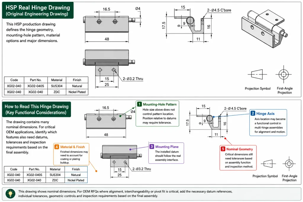
Build the Datum Scheme From the Assembly
The first tolerance decision is not a plus/minus number. It is the reference system from which the important features are located.
A hinge is constrained by real surfaces. One face may seat against a door, frame or welded bracket. A formed return may establish one direction. A locating hole, edge, boss or machined shoulder may remove the remaining freedom. The datum scheme should follow those physical contacts rather than whichever dimensions are easiest to place on the drawing.
A trimmed or stamped outer edge is not automatically a good datum. If the installer never locates the hinge from that edge, holding every mounting hole tightly from it may create precision in a relationship the finished equipment does not use.
Example datum scheme: On a bolt-on hinge, datum A may be the primary mounting plane, datum B the edge or formed return used to locate the hinge during assembly, and datum C a secondary locating feature. The actual datum scheme should follow the surfaces that physically constrain the hinge in the equipment.
If the project uses ASME Y14.5 or another defined dimensioning and tolerancing system, state that requirement on the drawing or through the applicable company drafting standard. The standard provides a common language for datums and geometric controls. It does not decide how much hinge-axis variation, position error or mounting-surface distortion the equipment can accept.
That limit still comes from the assembly. A supplier can evaluate manufacturability and inspection more accurately when the datum references correspond to features that exist in the real production and mounting process.
Mounting-Hole Position, Not Just Hole Size
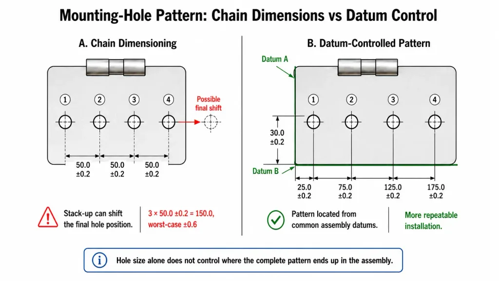
A mounting hole can have the correct diameter and still be in the wrong place.
The drawing needs to define both the hole itself and the allowed location of the complete pattern relative to the mounting references. Hole diameter, thread, counterbore, countersink or slot geometry answers one part of the question. Pattern position answers another.
Chained center-to-center dimensions deserve particular attention. If three consecutive dimensions are each specified at ±0.2 mm, a simple worst-case stack can place the final feature ±0.6 mm relative to the first. Every individual dimension may pass inspection while the accumulated location no longer supports the required assembly.
Whether ±0.6 mm is acceptable cannot be decided from the hinge alone. The available clearance in the mounting holes, hinge spacing, rigidity of the door and frame, latch position and required door gap all affect the boundary.
Locating a multi-hole pattern from common functional datums can remove unnecessary chain accumulation. Where the project’s GD&T system supports it, a position tolerance may communicate the pattern relationship more directly than several independent center distances.
| Mounting Feature | What Must Be Defined | RFQ Consequence |
|---|---|---|
| Clearance hole | Diameter, intended fastener and required assembly clearance | Changes hole process and available installation float |
| Threaded hole | Thread size, pitch, class and required engagement | Affects tapping, insert or machining route |
| Slot | Width, length and intended adjustment direction | Changes both installation freedom and location control |
| Countersink / counterbore | Geometry and intended fastener head | Can introduce additional tooling and depth control |
| Complete pattern | Location relative to functional datums | Defines how the supplier manufactures and inspects the interface |
Slots should solve a known adjustment problem. Making both leaves generously slotted in several directions may simplify prototype assembly, but it also removes repeatable location. Preserve positive location in directions that do not need adjustment.
Control the Hinge Axis as a Functional Feature
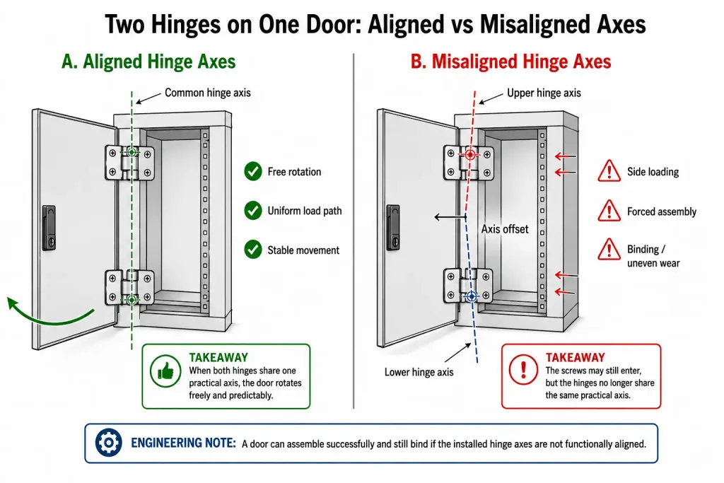
Two mounting patterns can be individually correct while their hinge axes are not functionally aligned. The screws may still enter. The door can become stiff as soon as they are tightened.
In a conventional pin-and-knuckle hinge, the rotation axis is established by the pin and the bores or bushings that support it. When two or more hinges carry the same rigid door, their individual axes have to become one practical assembly axis.
Position or angular error between those axes does not disappear because the fasteners fit. Instead, the door, frame, hinge leaves, brackets or bearing interfaces deflect until the parts can occupy the forced position. The result can be increased operating force, concentrated contact, uneven wear or a door that changes position after the fasteners are loosened.
The drawing should therefore control the production features that actually establish the axis. Depending on the hinge architecture, those may be:
- pin or bore location relative to mounting datums;
- mounting pattern relative to the intended hinge centerline;
- upper and lower hinge mounting zones on the door or frame;
- angular orientation of a formed or machined bracket;
- post-weld axis position rather than only the loose-component geometry; or
- an assembled functional condition when the resulting axis is more meaningful than a difficult internal dimension.
Do not add an arbitrary “coaxial within X” requirement without identifying what creates the axis and how the result will be inspected. A machined hinge, formed sheet-metal hinge and weld-on hinge do not produce their centerlines through the same manufacturing route.
Multi-link concealed hinges need another approach. Their door motion may not reduce to one exposed pin centerline. In that case, controlling mounting interfaces and the resulting mechanism position or motion envelope can be more useful than assigning a single-axis requirement that does not represent the mechanism.
Mounting Faces and the Tolerance Stack
The hinge does not install into free space. Its leaves sit against surfaces with their own thickness, form, angle and location variation.
A hinge leaf with a precise hole pattern can rotate out of position when tightened against a warped bracket. A flat leaf mounted across a weld bead can rock before the screws develop preload. Two nominally parallel mounting planes can twist the hinge axis when their orientation errors act in opposite directions.
Flatness, parallelism, perpendicularity or profile should therefore be applied where they control an actual mounting relationship—not across every visible surface.
A hinge installation stack can include leaf thickness, formed offsets, door and frame geometry, gaskets, spacers, paint, plating, washers, isolators, inserts and the axis offset from the mounting plane. Those contributors ultimately meet at the finished door gap, latch position, seal compression or mechanism clearance.
If the equipment allows only a limited total offset at the latch side, that entire allowance cannot be assigned independently to the hinge while the door, frame and mounting hardware consume the same dimensional budget. The allowable variation has to be allocated across the contributors that control the final condition.
For a guaranteed worst-case fit, review the extreme permitted combination of the relevant dimensions. Statistical tolerance methods can be useful in a mature production process, but they should not replace a guaranteed fit requirement unless actual process data supports the assumption.
Running Clearance and Axial Movement
“No play” is not a complete hinge tolerance.
A rotating hinge needs an intentional relationship between the pin and the interface that carries rotation. That interface may be a metal bore, polymer bushing, bronze bushing, bearing or another mechanism.
Removing every nominal gap can make the joint sensitive to normal size variation, finish buildup, temperature difference and installation error. Too much clearance creates the opposite problem: lateral movement, impact and unstable door position.
If pin-to-bore fit is a critical design variable, identify the actual rotating zone and the condition in which its limits apply. The detailed method for setting minimum and maximum operating clearance belongs in the hinge pin clearance guide.
Axial movement is separate. A pin can have an acceptable radial running fit while the assembled leaves still move along the pin axis because of knuckle gaps, washers, spacers, shoulders, bushings or retention features.
When that movement can affect latch alignment, detent engagement, seal position or equipment feel, add an assembly-level axial requirement instead of assuming one component gap controls the result. The hinge end-play guide covers the measurement boundary in detail.
Separate the controls: Pin clearance is a dimensional fit. Side play is lateral movement of the assembled hinge. End play is movement along the hinge axis. One value should not be used as a substitute for the others.
Opening Geometry on the RFQ Drawing
A note such as “opens 120°” is incomplete when the drawing does not show where the angular reference begins or what part of the assembly is being measured.
Where opening geometry affects the hinge RFQ, define the closed or zero-angle reference, the required service opening, any hinge detent or geometric stop position that belongs to the requested hinge, and the moving envelope required to avoid nearby structure. Removable hinges may also need a defined separation or lift direction.
Do not turn the hinge tolerance drawing into a complete door-stop design. When a structural stop, bumper, restraint or impact event controls the door, first-contact angle, allowable overtravel and stopping load belong in the separate industrial door opening-stop specification.
Dimensions Before and After Finish
Coating is not only a cosmetic requirement when it reaches a functional interface.
Plating, paint, powder coat and other surface treatments can change hole size, slot width, countersink seating, recess fit and running clearance. A pin and bore can both meet their pre-finish dimensions and become too tight after the final surface treatment.
Where finish affects function, the drawing should make the controlling condition clear. A critical limit may apply to the completed finished feature. The pre-finish dimension may instead reserve the full permitted coating buildup. Some rotating, threaded, grounding or seating surfaces may need masking or another controlled finish boundary.
A blanket note such as “all dimensions before coating” should not be copied across the drawing without checking the pivot, recess and mounting interfaces. Likewise, controlling every dimension after coating may add inspection difficulty without improving function.
This decision can change the supplier’s process. A bore that must remain inside a tight finished limit may need masking, finish allowance, reaming after treatment or another secondary operation. That cost should appear during quotation rather than after a sample binds.
Make Critical Tolerances Inspectable
A tolerance that cannot be measured consistently is not yet a complete production requirement.
Before releasing the RFQ, consider how each critical characteristic will be verified. A simple hole diameter may be checked directly. A mounting pattern may require measurement from the defined datums. A post-weld hinge axis may need inspection after the welded structure has cooled and been restrained in the specified condition. A functional end-play or operating-force requirement needs both a fixed reference and a defined measurement condition.
The drawing does not need to prescribe one inspection machine when several methods can demonstrate the same requirement. It does need to avoid definitions that allow manufacturing and quality teams to measure different things.
For a critical characteristic, make these points unambiguous where they affect the result:
- the datum or surface from which the measurement is established;
- the feature, axis, point or movement being evaluated;
- whether inspection occurs on the loose component or completed hinge;
- whether the measurement is before or after coating, welding, bushing installation or final assembly;
- the hinge position or orientation when movement changes the reading; and
- the functional acceptance limit when dimensional inspection alone does not prove the required behavior.
Some internal features become difficult to reach after assembly. In that case, it may be more practical to control the contributing component dimensions and periodically confirm the resulting finished condition. That relationship needs actual correlation. A nominal component stack should not be assumed to prove an inaccessible functional result without evidence.
The reverse problem also occurs. A supplier may be able to measure every component accurately while the final hinge still behaves differently because forming, staking, welding, press-fitting or fastener preload changes the assembled geometry. When the user experiences the assembled behavior, include an appropriate assembly-level check.
Process Capability Changes What Is Practical
The same numerical tolerance can be routine on one hinge feature and expensive on another because the manufacturing processes are different.
| Feature or Process | Variation the Drawing Must Consider | RFQ Question |
|---|---|---|
| Stamped leaf | Hole position, edge trim, burr, flatness and forming distortion | Which features must remain located after forming? |
| Formed bracket | Bend location, angle, springback and mounting-plane orientation | Which formed surface establishes the installed hinge position? |
| Machined pin or shaft | Diameter, shoulder location, straightness and surface condition | Which zones rotate and which zones remain fixed? |
| Cast or die-cast body | Profile variation, draft, local machining and hole location | Which surfaces are functional datums and which can remain as-cast? |
| Welded hinge or bracket | Heat distortion and post-weld centerline movement | Does the critical requirement apply before or after welding? |
| Completed hinge | Combined pin, leaf, bushing, washer and retention variation | Which final movement is more useful to control at assembly level? |
The functional limit still belongs to the equipment designer. Supplier process capability does not decide what the assembly can tolerate. It determines whether the proposed drawing can be produced economically by the selected route.
When a supplier requests a wider tolerance, ask which feature or manufacturing step creates the constraint and how the proposed change affects the functional stack. That conversation is more useful than arguing over a number without connecting it to the assembly.
The same scrutiny applies when an unusually tight tolerance is accepted without comment. Ask how the characteristic will be produced and inspected. A tolerance printed on a quotation does not prove a stable production process.
Example: A Drawing Can Fit and Still Bind
Consider a rigid industrial access door using two separate pin hinges. Each leaf has correctly sized mounting holes. Hole positions are dimensioned from local stamped edges, every linear dimension remains inside its stated ± tolerance, and both hinges can be screwed to the door and frame.
The assembly is still stiff.
The stamped edges used as dimensional origins are not the surfaces that actually locate the hinges in the equipment. Variation at those edges shifts the upper and lower mounting patterns in different directions. Once the fasteners are tightened, the two pin centerlines no longer form the same practical axis.
The holes still accept the screws because the door and mounting brackets flex enough to absorb the error. That compliance hides the alignment problem during assembly and reappears as side load at the pivot.
Making the holes larger may reduce assembly resistance but also increases positional freedom. Tightening every leaf dimension attacks the opposite end of the problem and may add manufacturing cost without controlling the actual installation relationship.
A more useful drawing locates the hinge patterns from stable assembly datums, preserves adjustment only where the installation needs it, and controls the production features that establish the rotation axes. If the completed door structure adds significant variation, final inspection also checks the resulting assembled geometry or movement instead of assuming that component dimensions prove it.
RFQ Drawing Fields Suppliers Need
An RFQ drawing does not need to contain every production detail on the first quotation revision. It does need to distinguish defined requirements from areas where supplier feedback is still expected.
| Drawing Field | What the Supplier Needs to See | Why It Belongs Before RFQ |
|---|---|---|
| Document status and revision | RFQ status, drawing identifier, revision and units | Prevents quotation against the wrong document basis |
| Drawing convention | Applicable dimensioning and tolerancing system | Aligns engineering and inspection interpretation |
| Mounting datums | Surfaces or features that locate the hinge in the equipment | Establishes the basis for critical dimensions |
| Mounting pattern | Hole, slot, thread and location requirements | Defines the actual installation interface |
| Intended fastener and substrate | Relevant fastener type and mounting material or thickness | Can change hole, thread, insert or joint design |
| Hinge axis or motion reference | Axis location or mechanism reference where function requires it | Controls movement and paired-hinge alignment |
| Pivot condition | Relevant fit, side-play or end-play requirement | Separates dimensional fit from assembly movement |
| Opening geometry | Required angle reference and motion envelope | Prevents static fit from being mistaken for motion clearance |
| Finish condition | Material/finish interface and when critical dimensions apply | Allows the supplier to price masking or secondary processing |
| Inspection condition | State in which critical characteristics are accepted | Prevents different inspection interpretations later |
| Supplier deviations | Every proposed departure from dimensional or tolerance requirements | Keeps quotations technically comparable |
When a requirement is not yet fixed, leave it open for engineering discussion rather than hiding the uncertainty behind a generic tolerance. A supplier that cannot meet a critical feature economically should return the proposed alternative visibly so the technical effect can be reviewed before the quotations are compared.
RFQ-Ready Drawing Checklist
Before the drawing leaves engineering, review it from the supplier’s side. A manufacturing engineer, toolmaker, quality inspector and estimator should be able to identify the same functional requirements without depending on a phone call to understand the design intent.
- Document identity is clear. Drawing number, revision, units and RFQ status are visible.
- Functional datums follow the real assembly. Critical features are not located from convenient but irrelevant edges.
- The mounting pattern is fully defined. Hole type, geometry and location are separate considerations.
- The hinge axis or mechanism position is controlled where it affects function.
- Multiple-hinge alignment has been considered. Individually acceptable parts must not create an impossible assembly stack.
- Mounting faces are controlled only where their form or orientation can move the installed hinge.
- Pivot clearance, side play and end play are treated as different characteristics.
- Opening geometry uses a defined reference and the required moving envelope has been checked.
- Critical dimensions identify the relevant finish condition.
- Tight tolerances have a functional reason and a plausible manufacturing route.
- Critical characteristics can be inspected in the state that actually controls acceptance.
- Supplier deviations must be returned explicitly rather than absorbed silently into the quotation.
A strong RFQ drawing does not contain the largest number of tolerances. It contains enough control that the supplier understands which relationships must repeat from part to part and which dimensions can vary without changing the installed hinge.
That is the practical purpose of defining industrial hinge tolerances before RFQ: turn assembly function into manufacturing requirements that can be priced, produced and inspected against the same drawing.
Send Your Hinge Drawing for RFQ Review
For a custom or modified industrial hinge, send the hinge drawing together with the mating door or frame interface, mounting method, required movement and the dimensions that control your assembly. HSP can review the requested configuration and identify dimensions or tolerance requirements that still need clarification before quotation. Send your hinge drawing and application details.
Industrial Hinge Tolerance Questions
What tolerance should I specify for an industrial hinge?
There is no universal tolerance for every industrial hinge. Set the limit from the function being controlled, such as mounting position, hinge-axis alignment, pivot clearance, axial movement, opening geometry or interchangeability. Noncritical dimensions can often remain under a general drawing tolerance.
Should hinge mounting holes use plus-minus dimensions or a position tolerance?
Either method can be valid under the project’s drawing system. A datum-based position control is often useful when the complete mounting pattern must stay located relative to functional references. Independent chained dimensions can accumulate variation, so the chosen method should reflect the assembly relationship that actually needs to be controlled.
Does the hinge axis need its own tolerance on the drawing?
Control the hinge axis when its location or orientation affects door movement, multi-hinge alignment, gaps, sealing or adjacent-component clearance. Depending on the hinge architecture, the requirement may control a pin or bore axis directly, the mounting pattern that establishes the axis, or a measurable completed-assembly condition.
Can the title-block general tolerance control the hinge mounting pattern?
Yes, but only when that general tolerance produces an acceptable installed position and alignment. A function-critical mounting pattern should not be left to the default tolerance by accident. Give it an individual requirement when the assembly needs a different limit.
Should hinge dimensions be specified before or after coating?
Use the condition that controls function. If plating, paint or another finish changes a bore, hole, slot, recess, mounting stack or running clearance, the tolerance should account for the finished condition. Noncritical features can follow the manufacturing and inspection condition appropriate to the process.
How tight should hinge pin clearance be?
Do not select a universal clearance or fit class from the hinge name alone. The acceptable range depends on the rotating interface, free-play limit, finish buildup, temperature, alignment, bearing length and manufacturing variation. Establish the functional minimum and maximum clearance before assigning pin and bore limits.
How should a critical hinge tolerance be inspected?
Define the datum, feature or movement being measured and the condition of the part when the result is accepted. Critical characteristics may need to be checked after forming, welding, coating, bushing installation or final hinge assembly when those processes change the functional geometry.
What should a hinge supplier return when quoting from my drawing?
The quotation should identify the drawing revision being quoted and list any proposed dimensional, tolerance, material, finish, process or inspection deviations. If a critical requirement cannot be held economically, the alternative should be returned explicitly so its technical effect can be reviewed before suppliers are compared.