-
+86 13720060320
-
lanna@haitangs.com

Weld-On Hinge Installation: Protecting the Pivot During Welding
Weld-on hinge installation needs three separate controls: protect the moving surfaces from spatter, keep welding current out of the pivot, and manage heat without reducing the specified weld. Support and align the door before tack-up, follow the selected hinge’s welding instructions, and accept the assembly only after it has cooled and received its final finish.
A free-swinging door at tack-up can still bind after welding or finishing. This procedure covers industrial equipment doors and enclosure panels whose hinge model and weld design have already been selected.
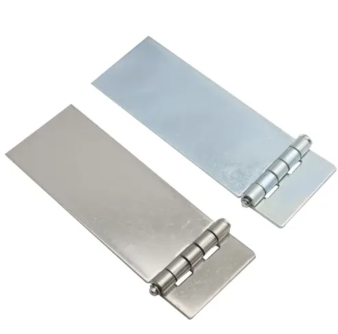
Weld-On Hinge Installation Starts With the Drawing
Before positioning the door, identify the hinge model, door and frame materials, local thicknesses, designated weld surfaces, and the required weld size and extent. The welding procedure must suit that joint. Any coating in the weld zone also needs a preparation method compatible with the material and coating; a plated surface should not be treated as bare steel.
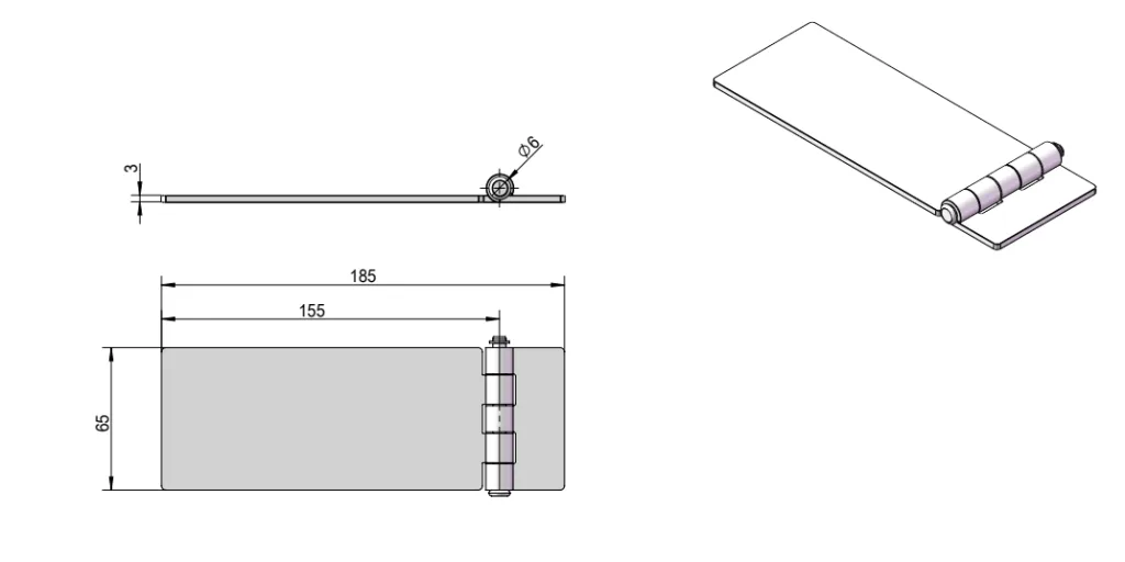
Use the selected hinge’s installation drawing to identify permitted weld surfaces and any areas that must remain unwelded. If it does not specify the weld detail or the assembly’s temperature limits, obtain that information before fabrication. The product outline and overall dimensions alone do not establish where or how to weld.
If the model, mounting structure, or material combination is still undecided, use the weld-on hinge selection guide first. This installation procedure does not determine load capacity or substitute for the weld design.
Parts That Must Come Off First
Door removal, hinge separation, and pin removal are different operations. A lift-off door may separate from its frame while the pin remains permanently fixed in one hinge half.
Identify the pin-retention arrangement in the selected model’s drawing or instructions. The word “detachable” describes a removal function; it does not, by itself, establish that the pin is removable.
| Hinge construction | Preparation decision | What needs confirmation |
|---|---|---|
| Loose-pin assembly | Remove the pin and associated parts only as the installation instructions allow. | Reassembly order, lubrication, retention, and the approved alignment method. |
| Lift-off assembly with a fixed pin | Separate the halves if permitted; protect the fixed pin and mating bore. | Which half carries the pin and whether it must remain in place during welding. |
| Sealed-bearing hinge or mechanism on weldable brackets | Follow the model’s instructions for welding assembled or removing the mechanism from its brackets. | Heat limits, protected surfaces, and whether disassembly is allowed. |
Do not press out a staked pin or open a sealed bearing without an approved dismantling and reassembly method.
Store removed parts in a clean, labeled container, keeping washers, spacers, and retainers in their documented reassembly order.
Spatter Protection Around the Pivot
Protect the surfaces that must still slide, rotate, seal, or accept a fastener after welding. These include the pin and barrel openings, thrust faces, exposed threads, lubrication fittings, and nearby gasket or cable surfaces.
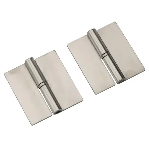
Use suitable welding shields or covers that leave the specified weld area accessible. Position them so spatter cannot collect behind the cover and fall into the joint when it is removed. Keep masking materials out of the molten weld and follow their temperature and fire-safety limitations.
If anti-spatter fluid is used, check its technical data sheet for the intended application, cleaning requirements, and compatibility with the planned finish. Do not assume a nozzle spray is suitable for component surfaces. Keep the fluid out of bearings, grease passages, and other interfaces unless the hinge and fluid instructions permit that use.
Keep these three controls separate:
- Spatter protection keeps molten droplets off functional surfaces.
- Heat control limits temperature exposure and welding distortion.
- Current-path control keeps the welding circuit from using the hinge pivot as a connection.
A clean-looking hinge can still have suffered heat or electrical damage; inspect its operating behavior as well as its surface.
The Welding Current Path
Place the work-return clamp on the member being welded, with clean, adequate contact and a direct current path that does not cross the hinge’s pin or bearing interfaces. When moving from the door-side leaf to the frame-side leaf, reassess the connection rather than leaving the clamp in its original position automatically.
TWI’s guidance on welding-current return paths describes how stray current can pass through unintended components, including bearings, and recommends a direct return connection near the arc. For a hinged door, trace that route before welding either side of the assembly.
A nearby clamp can still be on the wrong side of the moving interface. Trace the path, not just the distance.
This is the welding work-return connection, often called the ground clamp. It is distinct from the equipment’s protective grounding. For welding on an assembled machine, follow its electrical isolation and welding precautions before connecting the welder; moving the return clamp does not replace those requirements.
Tack-Up Before the Final Weld
Support the door with a fixture or lifting arrangement that controls its weight and position. The hinge should not be used to pull a twisted frame or bowed mounting surface into place. Establish the specified door gap and hinge axis without relying on latch force.
With the parts still supported:
- Position the hinges and check that the mounting surfaces seat as intended.
- Apply tacks in the specified locations and sequence, with the required pivot protection in place.
- Recheck the gap and axis before committing to the final weld.
- Where the approved fixture arrangement permits a movement check, compare operation with the pre-weld condition.
A movement check must not leave an unsupported door hanging from tacks that were never designed to carry it. If safe movement requires removal from the fixture, establish a supported test arrangement rather than improvising around the hinge.
Record whether resistance occurs throughout travel, at one opening angle, or only during latching. This gives the final inspection a useful baseline.
Detailed measurement of axis errors belongs in the industrial hinge axis alignment guide. For this installation, the immediate decision is whether the tack-up position is acceptable before more heat is added.
Heat Control Without Changing the Weld Requirement
Weld size and location define the required joint. Welding sequence determines how that joint is made. Depositing a continuous weld in controlled stages does not authorize an intermittent final weld. Any change to the specified size, length, or continuity needs approval from the responsible designer.
Use the sequence, process settings, and temperature controls required by the welding procedure and selected hinge. TWI’s guidance on controlling welding distortion explains how welding technique and sequence influence movement of the joint. Apply those principles through a procedure suited to the assembly, with any cooling intervals required by its thermal limits. Distortion control and protection of heat-sensitive hinge components must both be addressed.
A temperature limit is usable only when its measurement location and application are clear. The hinge barrel, the welded leaf, and the adjacent frame are different locations. A short pause or a temperature reading elsewhere on the door does not demonstrate compliance with a limit specified near the pivot.
Do not make water quenching or wet-rag cooling the default solution. Use a cooling method permitted by the joint procedure and hinge instructions. Managing temperature should not introduce an unapproved change to the welding process.
Smooth at Tack-Up, Tight After Welding
Consider an equipment door that moves freely in a supported tack-up check. The installer then completes the weld around one hinge before moving to the next. After cooling and fixture release, the door becomes stiff near mid-travel.
The timing makes welding distortion a candidate, but it does not establish the cause. Spatter at a thrust face, a changed door gap, or damage inside a bearing assembly could also affect movement. First record where the resistance begins, inspect the protected interfaces, and compare the cooled mounting position with the tack-up position. If geometry has moved, correct the mounting problem before considering a different hinge fit. Do not grind the pin smaller to make the door swing.
This is an illustrative engineering scenario, not a customer project record or product test claim.
Acceptance on the Cooled, Finished Door
Inspect the cooled assembly after controlled fixture release, maintaining safe door support. The fixture may have been holding the structure in a position it cannot maintain by itself.
Remove the protection carefully and clear contamination without driving debris into the pivot. Restore lubrication and reassemble components only as the model instructions require. Sealed bearings should not be treated as open, regreasable joints.
Assess the weld and the hinge function separately. Weld acceptance follows the drawing and applicable procedure. A door that swings smoothly does not prove that the weld has the required size or quality; a visually acceptable weld does not prove that the hinge operates correctly.
| Observation | First checks | Direction before acceptance |
|---|---|---|
| Resistance appears after final welding. | Cooled gap, mounting position, trapped spatter, and temperature records. | Identify the source before changing the pin fit or forcing the door. |
| The door rubs only near the closed position. | Frame clearance, latch engagement, gasket contact, and localized buildup. | Separate door interference from resistance inside the hinge. |
| Movement changes after painting or coating. | Finish on rotating interfaces, coating bridges, and the assembly’s approved cure exposure. | Address the affected finish or component; do not assume lubrication will solve it. |
| The hinge feels rough despite apparently correct alignment. | Accessible contamination, component condition, and the recorded welding-current route. | Escalate for component inspection; roughness alone does not prove electrical damage. |
Repeat the functional check after the specified corrosion-protection repair or final coating. Masking matters because finish can consume working clearance; the hinge pin clearance guide explains that fit issue in detail.
Acceptance should cover the specified opening range, clearance, latch engagement, and operating force. Agree any missing functional criteria before sign-off. Keep the tack-up and final observations with the hinge model and weld record.
For an HSP weld-on hinge installation review, send the selected model, a door-and-frame section with material thicknesses, the proposed weld locations, and photos of the pivot and mounting area. Browse the weld-on hinge range or send the installation details to HSP. Include the stage at which any resistance first appeared.
Weld-On Hinge Installation Questions
Can replacement hinges be welded with the equipment door installed?
Only if support, welding access, and equipment isolation requirements allow it. Protect or remove connected components according to the machine’s maintenance instructions. Provide independent door support before hinge removal; do not rely on the hinge being replaced.
Does a stainless steel hinge need less heat protection?
The external material grade does not establish the temperature limits of the complete assembly. A stainless steel hinge may still contain seals, lubricant, bushings, or a different pin material. Use the selected model’s welding instructions and internal construction to decide the protection needed.
Can the welded door go into a powder-coating oven?
Only after confirming that the hinge assembly tolerates the specified cure cycle. Welding approval and oven-exposure approval are separate. Some designs must be removed from their brackets before finishing, while others permit coating assembled. Masking the pivot keeps out coating; it does not protect internal parts from oven temperature.
Is “fully welded” enough information on an assembly drawing?
No. The fabricator still needs the permitted weld locations and the required size and extent. Welding every accessible edge may conflict with the hinge manufacturer’s restrictions. Resolve the weld detail with the responsible designer before fabrication; do not fill in missing requirements from a generic hinge tutorial.
Can the hinge pin serve as an alignment mandrel?
Only where the manufacturer’s installation method allows it. A working pin, a removable setup pin, and a dedicated alignment fixture serve different purposes. Do not force a pin through misaligned barrels or assume a fixture must remain installed during final welding. Follow the specified fixture-removal sequence.