-
+86 13720060320
-
lanna@haitangs.com

How to Select a Clean Room Hinge for Semiconductor Equipment
A clean room hinge can carry the door, fit the drawing, and still create the wrong contamination path.
The rotating joint may generate wear debris, move lubricant toward an exposed edge, shed particles from a coating or polymer, or force the door into a slightly misaligned closing path that increases contact inside the pivot. These risks are easy to miss when a review stops at material grade, load rating, and mounting dimensions.
For semiconductor equipment, the hinge should be treated as a small tribological system located at a defined cleanliness boundary. The engineering task is to identify where surfaces contact, what can leave the joint, where that material can travel, and whether service activity changes the approved condition.
This article takes that task to completion. It does not assign a universal cleanroom rating to any hinge, and it does not assume that stainless steel, a bushing, or a sealed appearance automatically proves suitability.
The Real Failure Path Starts Inside the Pivot
A conventional hinge review begins with the visible parts: leaf thickness, hole pattern, finish, hinge spacing, and door weight. The contamination risk begins one level deeper. Inside the knuckle or bearing housing, radial load, axial load, sliding motion, edge contact, surface finish, clearance, and lubricant behavior determine what the joint produces during operation.
A hinge may remain smooth while the contact surfaces polish each other. It may remain aligned while a small amount of wear material exits below the lower knuckle. It may look sealed while pressure changes or repeated opening move lubricant toward a gap. None of those outcomes is visible in a catalog photograph.
The first review question is therefore not whether the hinge is described as clean, hygienic, stainless, or low-friction. The first question is whether the drawing reveals the complete rotating interface.
Hold the proposal when the supplier cannot identify the pin, bearing or bushing, axial support, retention feature, lubricant location, exposed gaps, and the path from the pivot to the controlled space.
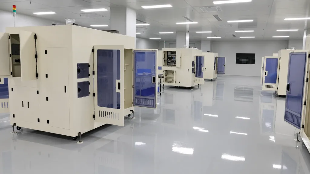
Define the Cleanliness Boundary Before the Hinge
A hinge installed on an outer utility cover does not carry the same contamination significance as a hinge beside a mini-environment opening. The same construction may be acceptable in one location and unacceptable in the other because the particle path, airflow relationship, and service activity are different.
Draw the equipment in section and mark the controlled volume before selecting the hinge. Show the process side, service side, local cover, gasket, door return, hinge axis, fasteners, drainage direction, and the lowest point where debris or cleaning residue may collect.
| Pivot Location | What Changes | Main Engineering Question | Evidence Needed |
|---|---|---|---|
| Outside the controlled boundary | The pivot is physically separated from the process volume | Can debris transfer during door opening, cleaning, or technician handling? | Section drawing, opening path, cleaning path, inspection access |
| Adjacent to the boundary | The joint sits near a seal, opening, airflow path, or exposed process-side surface | Can motion carry material toward the controlled area? | Boundary drawing, door swing, local cover, gasket and airflow-side geometry |
| Inside the controlled boundary | The rotating interface becomes part of the contamination-control problem | What does the joint generate under the real load and cycle condition? | Construction section, material data, lubricant statement, installed test |
| Across the boundary | The axis, mounting slot, or fastener creates a direct path through the enclosure | Does the hinge create a bypass around the intended seal or cover? | Cross-section, sealing detail, fastener path, assembly inspection |
| Removable across the boundary | The joint opens during service and exposes previously enclosed surfaces | What contamination is released or transferred when the panel is removed? | Removal sequence, captive-part design, panel handling and storage method |
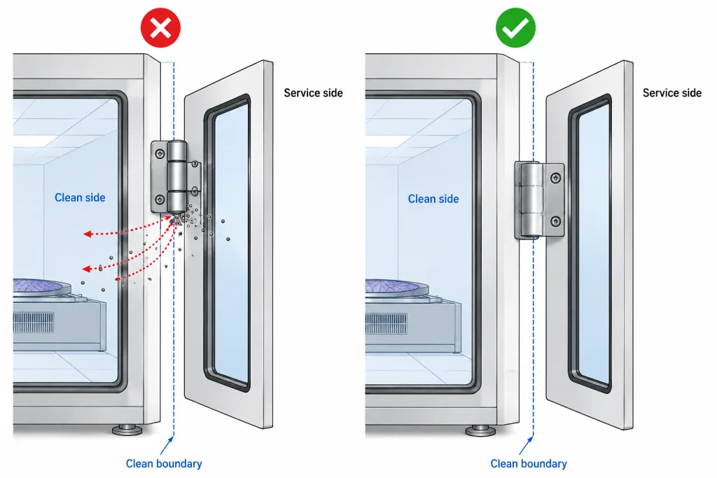
The boundary classification is not a certification. It is a design input. It determines how much construction detail, inspection access, containment, and sample evidence the hinge requires.
Six Ways the Hinge Can Generate or Release Material
Not every particle source is caused by gross damage. Small changes in contact, alignment, surface condition, and maintenance can release material long before the hinge becomes loose or difficult to operate.
| Mechanism | Typical Trigger | What May Be Released | What to Inspect |
|---|---|---|---|
| Adhesive sliding wear | Direct metal contact under load with repeated motion | Fine metallic transfer, polished debris, dark residue | Pin and knuckle surfaces, lower exit point, change in operating force |
| Abrasive wear | Hard debris, rough surface, damaged coating, or contamination inside the joint | Mixed metallic or coating particles | Scoring direction, embedded debris, coating damage, clearance growth |
| Fretting | Small repeated motion at fasteners, washers, or poorly seated interfaces | Dark oxide-like residue or fine wear particles | Fastener joints, washers, leaf-to-frame contact, looseness |
| Axial rubbing | Door weight or assembly error loads the end face of a knuckle or washer | Localized wear debris below the loaded end | Axial support, thrust surface, washer or bearing condition |
| Lubricant migration | Orientation, pumping action, heat, cleaning, or repeated motion | Oil film, grease trace, contaminated residue | Exposed edges, lower knuckle, adjacent panel and cleaning history |
| Surface or polymer shedding | Coating damage, polymer wear, creep, cracking, or chemical exposure | Coating flakes, polymer particles, fragments | Edges, retention features, bushing condition, contact marks |
These mechanisms can overlap. A small axis error can increase radial edge loading, which accelerates bushing wear, which opens clearance, which then increases impact and lubricant movement. The article therefore treats alignment, materials, and service as parts of one failure path rather than separate purchasing categories.
Radial Load, Axial Load, and Misalignment Are Different
Door weight is not one simple load at the pivot. The hinge may carry a radial reaction from the door moment, an axial load from gravity or installation orientation, and local edge contact from frame twist or axis error. Each load acts on a different surface inside the hinge.
For a vertical side-hinged door, the complete door mass and center-of-gravity offset create a moment around the hinge line. The upper and lower hinges share that load through the door and frame structure. If the frame is flexible, the door return is thin, or the two hinge axes are not coaxial, one hinge can carry more than the nominal share.
For a horizontal or inclined axis, gravity can push the rotating assembly toward one thrust face. A polymer washer, metal end face, or bearing shoulder may then become the main wear interface even though the radial bushing remains lightly loaded.
Drawing requirement: show the direction of gravity, door center of gravity, hinge spacing, pin centerline, axial support, and the surface that reacts the thrust load. A generic load rating does not reveal which internal interface carries that load.
Misalignment deserves its own review. A hinge can meet every catalog dimension and still bind when the two installed axes are slightly angular or offset. The door may feel acceptable because the frame flexes, but the flex is now forcing edge contact inside the pivot.
Pivot Architecture Changes the Failure Mode
Different pivot architectures control different risks. The purpose of comparing them is not to rank one as universally clean. It is to identify which contact surfaces remain, what they need to carry, and what evidence the supplier must provide.
| Architecture | What It Can Control | New Risk or Limitation | Supplier Return |
|---|---|---|---|
| Plain pin and knuckle | Simple load path and compact geometry | Direct sliding wear, galling risk, lubricant dependence, exposed debris path | Pin/knuckle materials, finish, clearance, lubrication and wear evidence |
| Polymer-bushed pivot | Separates metallic contact and can reduce friction | Polymer wear, creep, chemical or temperature limits, retention failure | Exact polymer, wall thickness, load limit, exposure restrictions, replacement policy |
| Rolling-element bearing | Reduces sliding at the primary radial interface | Bearing lubricant, seals, cage material, axial-load path, contamination from failure | Bearing type, seal/shield condition, lubricant, axial support, installation limit |
| Sealed or covered pivot | Blocks a direct path from the joint to the surrounding area | Cover can hide wear, trap residue, or create an uninspectable cavity | Section view, sealing method, inspection access, drainage and service procedure |
| Separated pivot outside boundary | Moves the rotating contact away from the controlled volume | Longer bracket load path, frame flex, cover penetration, larger envelope | Complete section, bracket stiffness, boundary sealing, alignment tolerance |
| Lift-off pivot | Allows full panel removal and direct service access | Loose parts, scraping, contamination transfer, reinstallation variation | Handing, disengagement path, captive features, seating datum, handling method |
A bushing is not a final answer. A bearing is not a final answer. A sealed appearance is not a final answer. Each architecture removes one mechanism and introduces another that must be shown on the drawing and checked in the installed condition.
Orientation Changes Where Debris and Lubricant Travel
The same hinge construction can behave differently when the axis, door, and cleanliness boundary are reoriented. Gravity changes which surface carries axial load and where loose material collects. Door motion changes whether a gap opens toward or away from the controlled space.
A vertical axis may allow wear material or lubricant to move toward the lower knuckle. A horizontal axis may keep debris inside one side of the housing while concentrating axial load at one end. An inclined axis can combine both effects and create a path that is not obvious in a front view.
- Mark the lower exit point. Show where gravity would carry loose material after cycling.
- Show the opening direction. A gap may face away from the process side when closed and face toward it when open.
- Include the service position. A door held open for maintenance may place the pivot in a different orientation for a long period.
- Review cleaning direction. Wiping or spraying can push residue into a joint that normally drains in the opposite direction.
- Check the installed cover. A local shield can redirect material, but it also needs inspection and cleaning access.
Door Duty Changes What Must Be Proven
A hinge on an operator access door, a scheduled maintenance panel, and a rarely opened utility cover should not receive the same validation plan. The number of cycles matters, but frequency alone is not enough. Opening speed, dwell angle, cleaning events, technician handling, and the consequence of failure change the evidence required.
| Door Duty | Dominant Concern | Validation Emphasis | Typical Hold Point |
|---|---|---|---|
| Frequent operator access | Repeated pivot wear and stable interlock/latch alignment | Representative opening speed, full working range, periodic visual inspection | Operating force or visible residue changes during cycling |
| Scheduled maintenance door | Contamination release during opening and service | Long dwell open, tool access, technician contact, closed-state recovery | Panel cannot return to the same seal or interlock condition |
| Removable service panel | Handling, scraping, loose parts, clean storage and reinstallation | Complete disengagement path, captive hardware, support and seating datum | Door edge or hinge leaf contacts the frame during removal |
| Rare utility cover | Corrosion, aging, seizure and first-open release | Long closed dwell, cleaning exposure, first operation after storage | Joint releases residue or requires excessive force after dwell |
| Large heavy access door | Load sharing, frame twist, edge contact and impact at travel limits | Full production mass, hinge spacing, stop/load path, paired-axis alignment | One hinge carries visibly different load or the frame pulls the axes out of line |
This task-based view keeps the article focused. It does not turn every door into a high-cycle application, and it does not treat a rarely opened panel as automatically low risk.
Lift-Off Access Can Solve One Problem and Create Three More
Removing the entire door can improve service access and keep a large panel out of the working opening. It can also create contamination transfer, loose-part, and alignment risks that do not exist with a captive door.
The removal path must be shown from fully closed to fully disengaged. The drawing should include the complete door envelope, overhead clearance, side clearance, operator grip space, cable or tubing release, the surface that supports the removed door, and the path used during reinstallation.
Use the lift-off hinge clearance and pin-direction guide for handing, axial disengagement, and anti-lift details.
For the separate decision on whether the panel should remain captive or become removable, use the removable access-panel hinge guide.
- Keep pins, clips, washers, and service tools captive or procedurally controlled.
- Prevent the leaf, pin, or door edge from scraping the frame during disengagement.
- Define a clean support or storage position for the removed panel.
- Disconnect cables, interlocks, gas lines, and tubing before the panel can load them.
- Provide a lead-in or seating datum that restores full hinge engagement without forcing the leaves together.
- Recheck the cleanliness boundary after removal because surfaces that were enclosed during operation may become exposed during service.
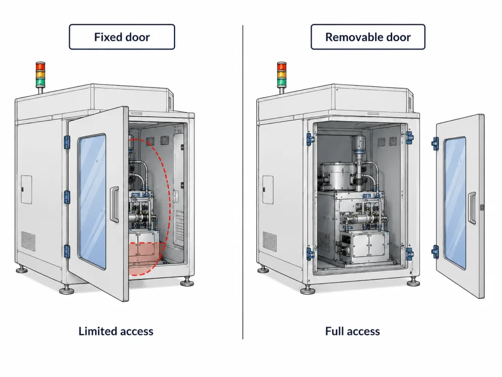
Reinstallation Must Restore the Approved Joint
A removable panel is not approved merely because it can be placed back on the hinge. Reinstallation must restore the same axis position, panel gap, gasket compression, latch engagement, interlock target, and pivot loading that were accepted before service.
A small seating error can change several conditions at once. The latch may pull the panel into position, increasing hinge-side compression. One hinge may seat before the other, creating angular misalignment. A cable may become trapped behind the door return. The equipment may still close, but the pivot is no longer operating in the approved state.
The panel closed, but the lower hinge started carrying the correction
The service panel returned to the cabinet and the latch engaged. The upper hinge was not fully seated, so closing the latch pulled the panel into alignment. The frame flexed enough to hide the error, while the lower hinge carried additional edge load inside the pivot.
The problem could not be solved by increasing latch adjustment. The design needed a clearer seating datum, an installation check at both hinges, and a closed-state inspection that did not rely on the latch to correct the panel.
This is an illustrative engineering scenario, not a customer project record or product test claim.
- Use common equipment datums to locate both hinge axes.
- Record the permitted slot or shim adjustment after installation.
- Check hinge-side and latch-side gaps before the latch is fully loaded.
- Verify seal compression around the perimeter rather than at one point.
- Confirm the interlock or sensor target after repeated removal and reinstallation.
- Inspect the pivot for new edge contact after the closed condition is restored.
Lubricants, Polymers, and Coatings Need Separate Boundaries
Material selection cannot stop at the hinge leaves. The supplier should identify the pin, bearing or bushing, thrust surface, washers, fasteners, retaining components, coatings, and lubricant. The location of each component matters as much as the material name.
A polymer bushing may separate metallic contact but introduce wear, creep, cracking, chemical sensitivity, or temperature limits. A coating may reduce friction but create a new source when damaged at an edge or press fit. A lubricant may reduce wear but migrate under gravity, pumping action, heat, or cleaning.
| Component or Treatment | Question to Answer | Evidence That Is Not Enough | Required Return |
|---|---|---|---|
| Polymer bushing | What load, speed, temperature, and exposure does it see? | “Low friction” or “engineering plastic” | Exact material, geometry, retention, operating limits and wear evidence |
| Rolling bearing | How are radial and axial loads carried? | Bearing brand or generic dynamic rating | Bearing type, seal/shield, lubricant, fit, thrust path and installation limit |
| Dry-film or plated surface | Which contact does the treatment protect and what happens if it wears? | Finish name alone | Base material, coating location, thickness/control method, damage or wear limits |
| Grease or oil | Can it move toward the exposed joint or process side? | “Pre-lubricated” | Lubricant identity or restriction, quantity/location, maintenance and migration limits |
| Stainless component | Which exact part is stainless and what contacts it? | “All stainless” without a bill of materials | Component-level grade/finish and mating-material description |
| Fastener locking feature | Can micro-motion create fretting or looseness? | Torque value alone | Locking method, mating surfaces, re-use policy and inspection access |
Do not merge separate claims: particle control, corrosion resistance, chemical compatibility, vacuum suitability, outgassing, ESD behavior, and cleanability are different requirements. Evidence for one does not automatically prove the others.
Build the Installed Test Around the Failure Path
A loose hinge on a bench can confirm basic motion and identify visible construction. It cannot reproduce door moment, paired-axis error, frame twist, gasket load, interlock alignment, removal handling, or the actual path from the pivot to the controlled space.
The installed test should therefore start from the failure mechanism identified during the drawing review. A direct metal-contact concern needs inspection of the contact and exit path. A lift-off concern needs repeated removal and seating. A lubricant concern needs the actual orientation, motion, dwell, and cleaning sequence.
Control the background before judging the hinge
Do not attribute every observed particle or residue to the hinge. The door, frame, gasket, fasteners, cleaning cloth, surrounding equipment, technician gloves, and assembly process may contribute background contamination. Establish a clean baseline and document the surfaces before operation.
Use the real duty profile
Record the opening range, speed, direction, dwell position, number of operations, door mass, mounted hardware, cleaning events, and service-removal sequence. The test condition should match the intended access task rather than a convenient bench cycle.
Inspect at planned intervals
Photograph the lower knuckle, exposed gaps, thrust surface, fasteners, adjacent witness area, and any cover or gasket. Look for visible debris, dark traces, scoring, lubricant movement, coating damage, polymer wear, looseness, or a change in operating force. The inspection interval is project-specific.
State what the test cannot prove
A visual inspection may identify obvious wear and migration, but it does not automatically prove airborne-particle performance, long-term life, chemical compatibility, vacuum behavior, or outgassing. Those claims require separately defined methods and acceptance criteria.
A Practical Sample Record
| Record Field | What to Capture | Why It Matters |
|---|---|---|
| Hinge identity | Part number, drawing revision, supplier lot or traceable sample ID | Links the result to the exact construction |
| Door assembly | Door revision, complete mass, center of gravity, mounted hardware and hinge spacing | Defines the real mechanical load |
| Pivot construction | Pin, bushing/bearing, thrust support, retention, lubricant and exposed gaps | Connects observed behavior to the contact system |
| Boundary location | Outside, adjacent, inside, or across the controlled space | Defines the contamination significance |
| Duty profile | Opening angle, speed, dwell, cleaning and service-removal sequence | Prevents a convenient but irrelevant test |
| Baseline condition | Photographs and inspection of pivot, fasteners, adjacent surfaces and door alignment | Separates pre-existing marks from test changes |
| Observation points | Visible debris, lubricant, scoring, looseness, operating-force change and alignment | Targets the identified failure path |
| Closed-state recovery | Panel gaps, gasket compression, latch effort and interlock position | Confirms reinstallation returns the approved condition |
| Test limitations | Claims not evaluated by the method | Prevents visual or cycle evidence from being overextended |
| Disposition | Proceed, hold for evidence, redesign, or repeat with corrected assembly | Turns the sample into an engineering decision |
Acceptance limits should be written before the test. A supplier’s internal cycle count, a clean-looking photograph, or smooth motion after cycling is not a universal approval criterion.
Evidence for the Exact Hinge Revision
The final approval package should tie the selected hinge construction to one controlled revision and one installed equipment condition. Do not approve a family name while leaving the internal pivot open to substitution.
Construction
- Controlled drawing and pivot section
- Pin, bushing, bearing, thrust surface and retention
- Lubricant identity/location or no-lubricant statement
- Component-level materials and surface treatments
Boundary
- Pivot location relative to the controlled volume
- Gasket, cover, airflow-side and process-side geometry
- Potential debris, lubricant and residue path
- Inspection and cleaning access
Mechanical Condition
- Door mass, center of gravity and hinge spacing
- Radial and axial load path
- Mounting tolerance, frame stiffness and paired-axis control
- Removal, handling and reinstallation method
Change Control
- Approved sample and drawing revision
- Controlled pin, bushing/bearing, coating and lubricant
- Supplier process or source changes that require review
- Conditions requiring a new installed sample
For general drawing fields, hole patterns, tolerances, and revision checks, use the hinge spec sheet and engineering drawing guide.
Send the Pivot Section and Cleanliness Boundary
Share the access-door section, complete door mass, hinge spacing, pivot construction, controlled-space boundary, operating orientation, service-removal requirement, material restrictions, and the evidence expected from the installed sample. HSP can compare the proposed architecture against the identified particle and service paths.
Clean Room Hinge Questions
What is a clean room hinge for semiconductor equipment?
It is a hinge architecture evaluated for wear-particle, lubricant, residue, service-handling, and alignment risks near a semiconductor equipment cleanliness boundary. Suitability depends on the exact pivot construction, location, load path, orientation, service duty, and installed evidence.
Does a clean room hinge generate zero particles?
A zero-particle claim should not be assumed. Bushings, bearings, protected pins, covers, and separated pivots can reduce specific mechanisms, but every rotating joint still requires model-specific and installed-condition review.
Why is stainless steel not enough for a semiconductor equipment hinge?
Stainless steel does not identify the pin, bushing, bearing, thrust surface, fasteners, coating, lubricant, alignment, or debris path. The complete pivot and every exposed component must be reviewed.
When is a lift-off hinge appropriate for semiconductor equipment?
Use it when full panel removal creates a real service or contamination-control benefit. Confirm disengagement clearance, captive parts, clean handling, cable or tubing release, panel support, and repeatable reinstallation.
What causes a dark line below a hinge knuckle?
Possible causes include sliding wear, fretting, axial rubbing, lubricant migration, coating damage, or debris already present in the assembly. The source cannot be confirmed from appearance alone; inspect the pivot section, load path, alignment, and residue location.
What should an installed clean room hinge sample prove?
It should connect the exact hinge revision to the real door load, cleanliness boundary, duty profile, removal method, pivot observations, and closed-state recovery. It should also state which claims were not evaluated.
Technical limitation: This article is a hinge-selection and evidence framework. It does not certify a hinge or finished semiconductor tool for cleanroom, process, vacuum, chemical, ESD, outgassing, environmental, health, or safety requirements. Model suitability and acceptance criteria remain project-specific.