-
+86 13720060320
-
lanna@haitangs.com

How to Select Railcar Door Hinges for Access Panels and Service Doors
A railcar door can fit its opening, latch correctly in the workshop, and still damage the hinge joint after the vehicle enters service.
Static door weight is only the starting condition. During operation, vertical and lateral vibration, shock events, frame movement, repeated latch pull-in, cleaning, weather exposure, and maintenance handling change the load at the hinge pin, mounting holes, fasteners, welds, and surrounding sheet metal.
The selection task for railcar door hinges is therefore specific: choose an architecture that keeps the access door aligned and retained through vehicle motion, then prove that the complete installed assembly returns to the approved closed condition after operation and service.
This page is limited to access panels, equipment doors, exterior hatches, and removable service panels on rolling stock. Passenger entry-door systems, powered operators, seats, folding tables, and structural vehicle articulations require different design ownership.
The Workshop Fit Is Not the Service Condition
A workshop fit check usually confirms that the door opens, clears the frame, and reaches the latch. It does not reproduce vehicle acceleration, repeated small-amplitude motion, wheel or track inputs, a distorted carbody interface, or the impact created when a heavy panel reaches its travel limit.
A hinge may survive the door weight while the mounting joint moves. The pin may remain fully retained while one bracket shifts inside a slot. The latch may still close because it pulls the panel back into position. That combination can create a false pass: the visible hardware remains present, but the released hinge axis and door geometry have changed.
The pin stayed in place, but the lower door gap changed
A side access door completed a vibration exposure without losing the hinge pin, clip, or mounting fasteners. It still opened and latched. The lower door gap had narrowed, however, and the striker carried a polished pull-in mark. One hinge bracket had moved within its slotted adjustment while the pin-retention witness marks remained unchanged.
The original acceptance rule—“no loose or missing hardware”—did not identify the actual degradation path. The follow-up review had to include slot position, hinge-axis location, the unloaded door gap, striker contact, and operating force.
This is an illustrative engineering scenario, not a customer project record or product test claim.
Selection boundary: do not release a railcar hinge from a catalog load value or a hardware-retention check alone. The door, hinge spacing, mounting structure, pin retention, latch, opening stop, environmental zone, and installed test condition must describe one assembly.
One Railcar Has Several Hinge Environments
The word “railway” does not define one hinge environment. A protected interior equipment door, an exterior side hatch, a roof access panel, and an underframe cover can see very different combinations of moisture, grit, de-icing residue, vibration, impact, public contact, and maintenance access.
| Installation Zone | Dominant Exposure | Hinge Decision | Evidence Needed |
|---|---|---|---|
| Interior equipment cabinet | Frequent service, vibration, limited aisle space, cable and interlock interfaces | Compact fixed, concealed, or removable architecture with repeatable closed alignment | Opening envelope, latch/interlock recovery, fastener and axis control |
| Exterior side access door | Rain, wash water, temperature change, impact, tampering, vehicle vibration | Protected pin and fasteners, drainage, corrosion system, structural stop | Material stack, finish, drainage path, retention and installed cycling |
| Roof equipment hatch | Water, UV, debris, technician loading, horizontal or inclined hinge axis | Thrust-load support, cover restraint, safe hold-open or independent support | Axis orientation, axial load path, service position and seal recovery |
| Underframe service panel | Ballast strike, grit, standing moisture, de-icing contamination, severe access limits | Shielded joint, secure retention, replaceable or serviceable architecture | Impact path, lower-edge contamination, tool access and loose-part control |
| Bogie skirt or removable exterior panel | High contamination, repeated removal, vibration, limited storage and handling space | Lift-off or retractable retention only when removal is controlled | Disengagement path, captive parts, support method and reinstallation datum |
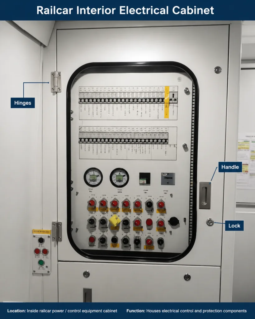
Select against the worst local zone, not the average vehicle environment. The lower hinge on an exterior door can require a different contamination and drainage review from the upper hinge even when both use the same model.
Door Moment During Vehicle Motion
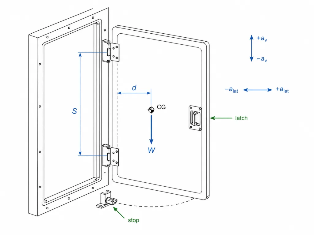
The static moment created by the complete door mass and its center of gravity still matters. It sets the baseline reaction at the hinge line. Vehicle motion then adds changing inertial forces and local distortion to that baseline.
Use the production-intent door mass, including windows, insulation, handles, lock rods, cable supports, covers, signs, and mounted equipment. A bare sheet-metal door can understate the moment and shift the center of gravity toward the hinge compared with the finished assembly.
The hinge pair does not automatically divide the load equally. Door stiffness, frame stiffness, hinge spacing, mounting tolerance, and latch position determine how the reactions are shared. A flexible panel can let one hinge carry the correction while the other appears lightly loaded.
For the detailed static door-moment and hinge-spacing calculation, use the heavy enclosure door hinge guide. This railcar page applies that load path to vibration, retention, environmental exposure, and installed service behavior.
Hinge Axis and Mounting Structure
The drawing may show matching holes and still leave the installed axes out of line. Weld distortion, formed-panel tolerance, bracket stack-up, slotted holes, paint build, shims, and frame twist can move one hinge relative to the other.
When the door closes, the latch can hide the error by pulling the panel into position. The joint now stores elastic load. During vehicle vibration, that load becomes repeated edge contact at the pin or bushing and micro-motion at the mounting interface. In the illustrative door above, the decisive change was not a missing pin; it was movement inside the slotted mounting adjustment.
Dimension the hinge pin centerline from controlled vehicle and door datums. Define the mounting-face condition, reinforcement, fastener or weld architecture, allowable adjustment, and the final axis check after finishing and installation.
When the frame or door edge uses thin sheet, transfer the attachment design to the thin sheet-metal hinge mounting guide. Increasing hinge size does not correct a flexible or poorly reinforced mounting edge.
Vibration Loosens More Than Fasteners
Rail vibration does not act only on screws and nuts. It can produce small relative motion at the leaf-to-panel interface, pin retention, bushings, washers, weld toes, slotted adjustments, latch contact, and opening stops.
| Interface | Possible Service Change | Visible or Measurable Evidence | Required Action |
|---|---|---|---|
| Hinge fastener joint | Preload loss, fretting, slot movement, local sheet deformation | Witness marks, dark residue, torque loss, shifted washer or slot position | Define locking method, joint stack, surface condition and post-test inspection |
| Pin retention | Axial walking, clip rotation, thread loosening, end-form damage | Changed end position, missing witness mark, clip movement or end clearance | Use a positive retention method and record axial position before and after test |
| Bushing or bearing | Wear, creep, brinelling, edge loading, increased clearance | Door play, rough motion, debris, operating-force change | Inspect the exact support interface under the installed load and orientation |
| Welded mounting | Crack initiation, local distortion, coating failure near the weld | Crack indication, paint line, changed axis, door-gap shift | Control welding sequence, support geometry and post-test inspection |
| Latch and striker | Repeated pull-in corrects door sag or frame movement | Higher closing force, polished contact, striker shift | Measure the door before latch pull-in and verify the hinge line independently |
| Opening stop | Impact load transfers into hinge or door skin | Bent bracket, loose hinge, local deformation, cable or seal damage | Make the stop load path independent of the cable, seal and hinge end travel |
A fastener that remains tight does not prove the joint stayed stable. A hinge pin that remains present does not prove the released geometry stayed unchanged. This is why the lower-gap scenario matters: the vibration review must follow the whole path from slot movement to axis shift, latch pull-in, local pivot loading, and closed-door recovery.
Pin Retention and Loose-Part Control
A removable pin can simplify assembly and service. On a moving rail vehicle, it also creates a retention decision. The project must define whether the pin may move axially, whether a technician may remove it, whether the retention part remains captive, and what happens if the door is opened or serviced in an abnormal orientation.
A formed or headed end is compact and visually simple, but it can make field replacement difficult. A retaining ring or clip is serviceable, yet the groove, clip orientation, access direction, and loose-part risk must be visible on the controlled drawing. Threaded retention supports planned disassembly only when the locking method, tightening instruction, and re-use policy are defined.
Cross-pins, captive locking pieces, and retractable spring-loaded pins can make engagement easier to inspect. They also add components that must remain retained through vibration and maintenance. The right architecture is the one that provides positive retention without creating an uncontrolled service item.
Mark the approved axial pin position on the drawing or inspection record. Record the retention feature before and after the assigned exposure. Then keep that check in context: in the opening scenario, the pin position did not change, but the mounting bracket moved and the lower gap still shifted.
Fixed, Concealed, or Lift-Off?
The architecture follows the access task. The question is not which hinge type sounds most robust; it is which joint can remain aligned, retained, inspectable, and serviceable in the actual vehicle location.
Fixed and Captive Doors
A fixed surface-mounted hinge keeps the panel attached during routine inspection and reduces loose-part handling. It is often the clearest option when the pin, fasteners, drainage path, and mounting interface must remain easy to inspect. The door still needs an independent opening stop and a latch that does not correct hinge-line error on every closing cycle.
Concealed or Protected Hardware
A concealed or internally protected hinge can reduce casual access to exterior pins and fasteners. That benefit is useful on public-facing or weather-exposed doors only when the internal joint remains reachable for inspection, adjustment, drainage, and replacement. Hiding the joint is not the same as controlling it.
Lift-Off Service Panels
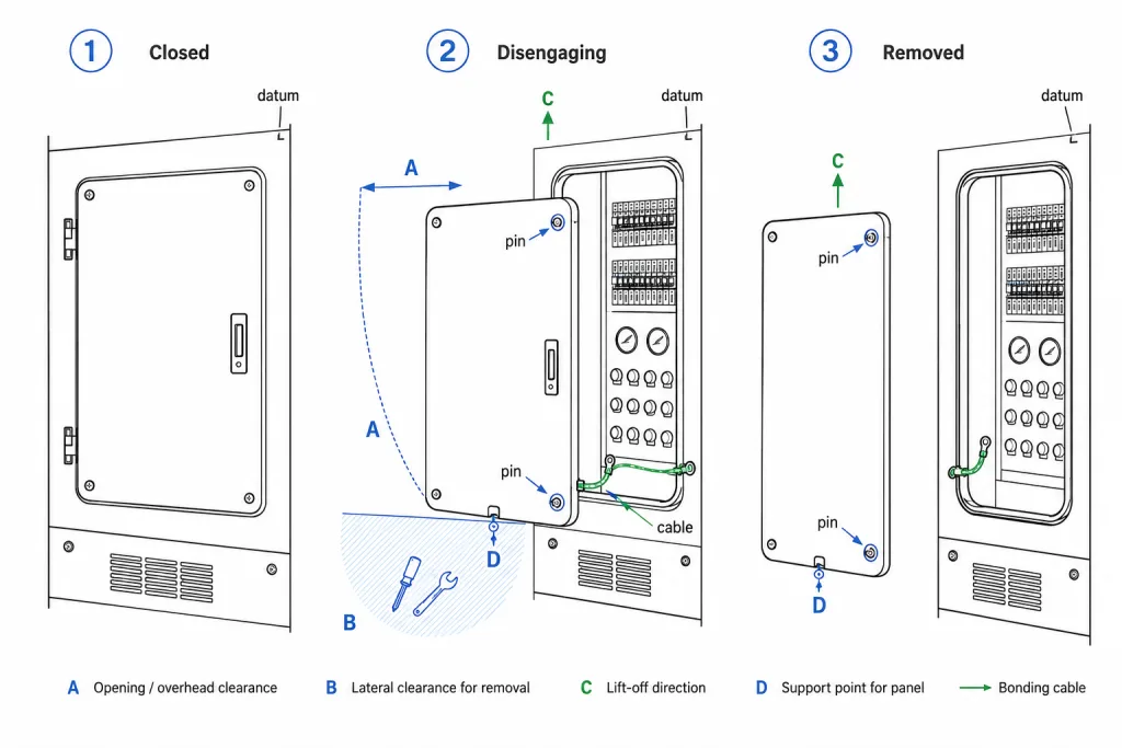
A lift-off or retractable-pin arrangement can clear the full maintenance opening and shorten module replacement. It also changes the service task: the technician must disengage the panel safely, control every loose component, support the door, release cables or bonding straps, and restore the same seating datum during reinstallation.
Do not choose a removable hinge because the door lifts off on a bench. The finished vehicle must provide the axial space, hand position, support route, and repeatable reinstallation condition needed by the real service operation.
Service Opening and Removal Envelope
A railcar panel may open beside seats, trim, equipment racks, handrails, cable routes, platform-side structures, roof hardware, or underframe obstacles. A maximum hinge angle on a product drawing does not describe the usable maintenance opening.
Draw the panel in the installed vehicle context. Dimension the nearest obstruction through the full swing as clearance A. Show the technician and tool zone as B. When the panel is removable, add the axial or vertical disengagement travel C and the point D where the panel weight transfers from the hinge to the technician or support fixture. The usable service angle θ should come from the maintenance task, not the catalog limit.
The same drawing should show the handle, latch rods, bonding strap, harness, pneumatic line, seal, and connector-release sequence. A removable door is not a complete solution when a cable, bonding path, or trim panel becomes the true travel limit.
For detailed handing, axial clearance, and reinstallation geometry, use the lift-off hinge clearance and pin-direction guide.
Stops, Latches, and Cables Share the Door System
The hinge should not become the accidental opening stop. Repeated impact at the hinge end travel can bend leaves, loosen the mounting edge, damage the pin support, or move the door relative to the latch and seal.
Use a structural stop or restraint with a defined load path into suitable vehicle structure. The cable harness, bonding strap, pneumatic line, gasket, or latch rod should not limit the opening angle.
The latch also affects hinge behavior. If it pulls a sagging or twisted panel into position, the closed door can look acceptable while the hinge remains side-loaded. Record door gaps and hinge-axis condition before the latch applies its final pull-in force.
Integrated acceptance: after vibration or repeated service, verify the hinge, stop, latch, seal, interlock, bonding path, and cable condition together. Passing one component does not prove the access system returned to the released condition.
Corrosion Starts at the Lower Hinge
Exterior and underframe rail equipment can collect water, grit, wash residue, and de-icing contamination around the lower hinge. Moisture remains in knuckle gaps, behind overlapping leaves, under fastener heads, at weld toes, and inside pockets long after the surrounding panel appears dry.
Review the hinge as a material and drainage system. Identify the leaf, pin, bushing, washer, clip, fastener, weld, coating, lubricant, reinforcement, and adjacent vehicle skin separately. A stainless leaf does not define the pin or retention part, and a coating name does not describe damage at holes, edges, welds, or service-tool contact points.
The lower joint needs a visible drainage path and inspection access. Galvanic combinations, trapped debris, damaged finish, and a nonreplaceable service item can matter more than the nominal material family. Where exposure is expected to consume a component, the replacement method should be designed rather than improvised.
Salt-spray duration, a stainless-steel label, or a coating name does not establish rail service life. The project must state the specimen condition, exposure, duration, allowable material change, post-exposure function, and acceptance criteria.
IEC 61373 — Scope and Limits
At the time of publication, the current edition is IEC 61373:2026. It defines shock and vibration test requirements for equipment intended for use on railway vehicles and can provide a project framework when the complete door, equipment cabinet, or mounted assembly is assigned to an applicable railway equipment category.
The standard does not automatically qualify a stand-alone mechanical hinge. It also does not replace the project decision about the real vehicle interface, mounting joint, door mass, latch, stop, service condition, and the acceptance evidence needed for the access assembly.
Even when IEC 61373 is assigned, the hinge acceptance rules remain project-specific: no lost retention, no harmful movement at slots or fasteners, permitted door-gap change, latch and interlock recovery, operating-force limits, corrosion condition, crack inspection, and post-test serviceability.
Standard boundary: use IEC 61373 to define the assigned equipment shock and vibration exposure when applicable. Do not use the standard name as proof that an unspecified hinge model, fastener joint, or railcar door assembly is approved.
Installed Sample Validation
A loose hinge sample cannot reproduce the railcar door moment, paired-axis error, mounting-edge flexibility, latch pull-in, opening-stop impact, cable force, corrosion traps, or the service-removal sequence. Use a production-intent door assembly or a documented fixture that reproduces the critical interfaces.
Baseline Before Exposure
Record pin-end position, retention parts, fasteners, welds, slot locations, unloaded door gaps, latch and striker contact, opening-stop condition, cables, bonding paths, and lower drainage points. The baseline must capture the geometry that a later latch pull-in could hide.
Operate the Real Door
Use the approved opening range, speed, dwell, service handling, and removal sequence. Apply the assigned shock and vibration condition in the documented orientation and mounting state. A convenient bench position can change axial loading, drainage, and which joint carries the door correction.
Follow the Degradation Path
Inspect for fretting, shifted slots, pin movement, debris, coating damage, cracks, looseness, increased play, and operating-force change. Then connect each observation to the door system. In the illustrative case, the useful chain was slot movement → axis shift → lower-gap change → striker pull-in, not simply “hardware present.”
Repeat Service and Verify Recovery
When removal is part of maintenance, disengage, support, store, and reinstall the panel using the intended service method. Recheck gaps before latch pull-in, seal compression, latch effort, interlock position, stop condition, cable route, bonding, drainage, and tool access.
Write acceptance criteria before testing. “Door still opens” and “no hardware missing” are not enough for a railway access assembly.
Sample Record and Release Evidence
| Record Field | What to Capture | Why It Matters |
|---|---|---|
| Hinge identity | Part number, drawing revision, handing, orientation and traceable sample ID | Connects the result to one exact construction |
| Vehicle interface | Door revision, complete mass, center of gravity, hinge spacing, frame and reinforcement | Defines the real load and mounting condition |
| Architecture | Fixed, concealed, lift-off, pin and retention method, bushing or bearing | Prevents substitution of a different internal joint |
| Environmental zone | Interior, exterior, roof, underframe, wash, salt or grit exposure | Sets corrosion, drainage and inspection needs |
| Closed baseline | Unloaded door gaps, slot and washer position, latch/striker contact, seal or interlock condition and operating force | Shows whether vibration or service changed the released geometry |
| Shock/vibration setup | Applicable requirement, mounting category, axes, fixture and deviations | Makes the result repeatable and interpretable |
| Post-test condition | Fasteners, pin position, slot movement, welds, cracks, play, debris, finish and unloaded door gaps | Connects interface changes to the complete degradation path |
| Service action | Opening, removal, panel support, cable release and reinstallation | Confirms maintenance remains practical after exposure |
| Limitations | Conditions not evaluated by the sample | Prevents one test from being extended to other vehicles or zones |
| Disposition | Proceed, hold for evidence, correct the assembly, redesign or repeat the test | Closes the engineering decision |
For general drawing revision, tolerance, hole-pattern, material, and performance-note interpretation, use the hinge spec sheet and engineering drawing guide.
Evidence for the Released Railcar Hinge
The release package should connect the selected railcar door hinge to the vehicle interface, service task, environment, and installed validation. A family description such as “heavy-duty stainless hinge” is not a controlled part definition.
Controlled Construction
- Hinge drawing and revision
- Pin, bushing or bearing, washers and retention
- Leaves, brackets, fasteners, welds and reinforcement
- Materials, finishes and lubricant restrictions
Vehicle Interface
- Door mass, center of gravity and hinge spacing
- Controlled datums and hinge-axis location
- Latch, stop, seal, interlock and cable path
- Opening and removal envelope
Rail Environment
- Installation zone and orientation
- Shock and vibration assignment
- Moisture, wash, grit and de-icing exposure
- Inspection and replacement access
Sample and Change Control
- Production-intent sample identity
- Installed test record and acceptance criteria
- Approved adjustment and service method
- Changes requiring engineering review or re-sampling
Send the Railcar Door Section and Service Envelope
Provide the complete door mass, hinge spacing, mounting section, installation zone, opening and removal envelope, pin-retention requirement, latch and stop details, environmental exposure, and the installed evidence expected by the project. HSP can review the hinge architecture and drawing inputs before model comparison or sampling.
Railcar Door Hinge Questions
What type of hinge is used on railcar access doors?
Railcar access doors may use fixed surface-mounted, concealed, bearing-supported, weld-on, or lift-off architectures. The correct type depends on the door moment, vibration and shock exposure, installation zone, security, service opening, removability, and required closed alignment.
Are railcar door hinges selected only by door weight?
No. Door weight and center of gravity define the baseline moment, but vehicle vibration, frame movement, hinge spacing, latch pull-in, mounting stiffness, pin retention, opening stops, corrosion exposure, and maintenance handling can control the final selection.
When should a railcar service panel use a lift-off hinge?
Use a lift-off architecture when full panel removal creates a clear maintenance benefit and the vehicle provides enough disengagement clearance, controlled panel support, captive hardware, cable release, and a repeatable reinstallation datum.
Does IEC 61373 certify a railcar hinge?
IEC 61373 defines shock and vibration testing for railway vehicle equipment within its scope. At the time of publication, the current edition is IEC 61373:2026. It does not automatically certify a stand-alone mechanical hinge or an unspecified door assembly. The project must define applicability and hinge-specific acceptance criteria.
What should be checked after rail vibration testing?
Check fastener and slot movement, pin retention, welds, cracks, play, fretting, debris, finish damage, operating force, door gaps, latch contact, seal or interlock recovery, stop condition, cable routing, and the normal service-removal procedure.
Should a railcar hinge sample be tested on the real door?
Yes when behavior depends on door mass, hinge spacing, frame stiffness, latch pull-in, stops, cables, seals, removal handling, or mounting tolerances. A fixture may be used only when it reproduces the critical production interfaces and is documented.
Technical limitation: This article provides a railcar access-door hinge selection and validation framework. It does not approve a hinge for a specific vehicle, passenger door system, structural carbody function, fire requirement, safety function, or regulatory program. Project drawings, assigned standards, vehicle interfaces, and production-intent sample evidence remain controlling.