-
+86 13720060320
-
lanna@haitangs.com

How to Measure Hinge Torque | Test Setup and Method
Knowing how to measure hinge torque requires more than attaching a gauge and recording the highest number. A torque hinge can show different resistance when movement starts, while it is rotating, when direction reverses, after it rests, at different angles, and at different temperatures. The result also changes when the fixture is misaligned or when a force gauge is applied at the wrong lever arm.
The first task is to define which torque behavior the drawing or specification requires. The second is to build a fixture that reacts the hinge without adding uncontrolled friction or flex. The third is to control direction, angle, speed, dwell time, preconditioning, temperature, and data treatment so another operator can reproduce the result.
This article begins after the project has identified a torque or friction hinge as the mechanism of interest. For the general operating principle and product families, see what a torque hinge is.
Measurement boundary: The required torque and the measured torque are different engineering questions. Required torque comes from the panel load and geometry. Measured torque is the resistance produced by the hinge or complete assembly under a defined test condition.
Define Which Hinge Torque You Need to Measure
A single value labeled “hinge torque” is incomplete. Before selecting the instrument, decide which portion of the motion curve will become the reported result.
| Torque Output | What It Represents | Why It Matters |
|---|---|---|
| Holding torque | Resistance available while the hinge or panel is at rest under the stated condition | Determines whether the load remains in position without unacceptable drift |
| Breakaway torque | The peak required to start movement after a defined dwell period | Excessive breakaway can make the panel feel stuck before it jumps |
| Running torque | Resistance after movement begins, usually evaluated over a defined angular window | Controls operating feel and steady movement |
| Opening torque | Measured resistance in the defined opening direction | May differ from the reverse direction because of geometry or one-way design |
| Closing torque | Measured resistance in the defined closing direction | Reveals directional asymmetry and return effort |
| Peak torque | Highest valid reading inside the defined test window | Useful for starting peaks, local interference, or overload risk |
| Average torque | Mean value over a stated angle range after excluding any defined transient | Useful for production comparison when the running region is stable |
| Torque variation | Change with angle, direction, specimen, or repeated sweeps | Reveals ripple, stick-slip, poor alignment, or process inconsistency |
Do not call the highest recorded point “holding torque” unless the test method actually measures resistance at rest. Do not report an average without stating the angular window. Do not compare an opening peak from one supplier with a running average from another.
If the project still needs to determine the target torque from panel mass and center-of-gravity distance, complete the torque hinge requirement calculation before using this page to verify the hinge output.
Choose a Hinge Torque Measurement Method That Matches the Decision
| Method | Best Use | Main Limitation |
|---|---|---|
| Direct rotary torque sensor | Engineering characterization, torque-angle curves, directional comparison, and controlled speed | Requires a well-aligned rotary fixture and suitable couplings |
| Torque gauge or torque tester | Bench measurement of compact hinges when the fixture can connect directly to both sides | Commercial grips may need custom adapters to prevent slip or off-axis load |
| Force gauge with a known lever arm | Low-cost checks, large hinges, or installed panels where direct coupling is difficult | Result is accurate only when the perpendicular lever arm and force direction are controlled |
| Complete panel handle-force test | Verifying what the user feels on the assembled equipment | Includes gravity, cables, seals, bracket flex, and other friction; it is not automatically hinge-only torque |
| Production go/no-go fixture | Fast screening after the engineering method is approved | Usually provides less detail and must be correlated to the controlled characterization method |
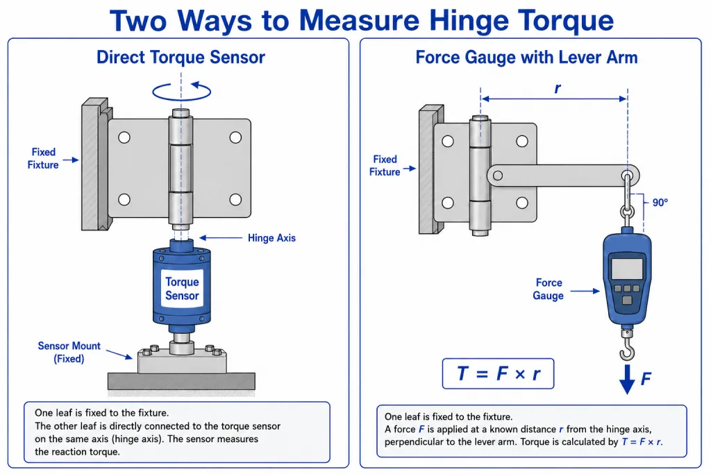
Use a direct torque sensor when the engineering decision depends on the shape of the torque-angle curve, small differences by direction, or repeatable comparison between samples. Use the lever-arm method when the fixture geometry is easier to control than a coaxial coupling and the required accuracy is compatible with the measurement uncertainty.
An installed panel test answers whether the finished product feels and holds correctly. A hinge-only bench test answers what the hinge produces. Both can be necessary, but they should not be reported as the same result.
Freeze the Specimen and Test Conditions Before Measuring
For torque verification and quality testing, results are not portable unless the specimen and conditions are controlled. A test request should identify the following fields before the first reading.
| Test Field | What to Record | Effect on the Result |
|---|---|---|
| Hinge identity | Model, drawing revision, lot or batch, material, finish, and adjustment state | Prevents mixing different constructions or settings |
| Assembly condition | Hinge alone, mounted brackets, paired hinges, complete panel, fasteners, and tightening condition | Adds or removes interface friction and structural compliance |
| Direction | Clockwise/counterclockwise or opening/closing using a clear reference view | Many hinges are not perfectly symmetric |
| Angular range | Start angle, end angle, measurement windows, and excluded end-stop zones | Torque may change through the rotation |
| Rotation speed | Defined speed or movement time through the test window | Friction, lubricant behavior, and data capture can be rate-sensitive |
| Dwell time | Time at rest before breakaway or holding measurement | Static friction and lubricant redistribution can change the starting peak |
| Preconditioning | Number and direction of sweeps before recorded data; Project-Specific | New or recently adjusted hinges may settle during initial movement |
| Temperature | Specimen temperature, room or chamber condition, and soak time | Friction materials and lubricant viscosity can change |
| Orientation and external load | Axis direction, gravity direction, and attached mass if any | Gravity may add or subtract from measured resistance |
| Lubrication and cleaning | As-supplied state and any permitted treatment | Cleaning or added lubricant can invalidate comparison |
Do not omit “minor” setup details from the report. A difference in dwell, speed, angle, or orientation can be larger than the difference between two acceptable hinges.
Model-specific evidence wins: When the supplier drawing or approved test instruction defines the measurement angle, speed, direction, temperature, or preconditioning, use those conditions rather than a generic laboratory habit.
Build a Coaxial Fixture for Direct Torque Measurement
A direct rotary setup needs one side of the hinge fixed to the reaction frame and the other side connected to the torque sensor or driven rotary axis. The fixture must transmit rotation without forcing the hinge shaft sideways.
- Common axis: Align the sensor axis, coupling, and hinge axis. Angular or lateral misalignment adds bearing load and false torque.
- Rigid reaction side: Prevent the fixed leaf, bracket, or housing from moving under torque.
- Low-backlash connection: Use an adapter that fits the hinge interface without slipping, rocking, or clamping the moving parts.
- No fixture rubbing: Keep leaves, brackets, screws, and guards clear through the entire angular range.
- Defined zero position: Mark the reference angle so opening and closing data use the same coordinate system.
- Overtravel protection: Stop the machine before the hinge or fixture reaches an unintended structural stop.
- Suitable sensor range: Choose a calibrated range that resolves the expected torque without approaching overload.
- Stable sampling: Capture enough data to identify the starting peak and running region without filtering away valid behavior.
Flexible adapters may reduce assembly stress but can store torsional energy and distort the apparent breakaway event. Very rigid couplings can transfer misalignment directly into the sensor and hinge. The fixture design must balance alignment, stiffness, and practical installation.
Tare the sensor after the fixture is assembled in the defined starting position. If the fixture itself produces measurable torque, characterize that baseline through the same angle range and document whether it is subtracted from the hinge result.
Measure Hinge Torque With a Force Gauge and Lever Arm
A force gauge can measure hinge torque when the force is applied at a known perpendicular distance from the hinge axis. The generic relationship is:
Generic formula: T = F × r⊥. If the applied force is not perpendicular to the lever arm, T = F × r × sin(α), where T is torque, F is measured force, r is the distance from the hinge axis to the force application point, and α is the angle between the lever arm and force direction.
For example, a measured force of 20 N applied perpendicular to a 0.15 m lever arm represents 3 N·m. This is a formula demonstration, not a recommended hinge value.
Control the Lever-Arm Geometry
- Measure from the true hinge axis to the line of action of the force—not to the edge of the handle or a convenient screw.
- Keep the gauge force perpendicular to the lever arm at the measurement angle, or use the sine correction.
- Use a rigid lever that does not bend appreciably under the measured force.
- Prevent the hook, push tip, strap, or contact roller from sliding during the reading.
- Record whether the gauge pushes or pulls and how the force direction maps to opening or closing.
Separate Manual Screening From Controlled Measurement
A handheld gauge is useful for troubleshooting and preliminary comparison, but operator speed, force direction, and peak capture can vary. A motorized stand, controlled linear axis, or guided pull path improves repeatability when the result is used for sample approval or production limits.
When the lever arm changes angle relative to a fixed linear gauge, the perpendicular distance also changes. Either measure at one defined angle, reposition the gauge to remain perpendicular, or calculate the changing geometry. Do not use one constant lever arm across an arc when the line of action is not constant.
Measure and Record the Torque-Angle Curve
A single maximum value can hide the behavior that users actually feel. Record torque against angle when the project needs to distinguish starting resistance, steady movement, local peaks, direction changes, or angular variation.
- Install and identify the specimen. Confirm the model, revision, orientation, direction, fixture, and adjustment state.
- Warm up and zero the system. Follow the instrument procedure and tare the assembled fixture at the defined start.
- Precondition the hinge. Move it through the approved cycles and directions before recorded sweeps; the exact count is Project-Specific.
- Apply the dwell condition. Hold the specimen at the start angle for the defined time when breakaway is measured.
- Rotate at the defined speed. Record torque and angle continuously or at a controlled set of positions.
- Exclude invalid regions. Do not include fixture take-up, impact with a stop, cable snagging, or movement outside the approved range.
- Reverse direction under the stated condition. Record opening and closing separately rather than combining them.
- Repeat the sweep. Use the project-defined repeats and review whether the result stabilizes or continues changing.
- Save the raw curve. Keep the unfiltered data, calculated outputs, specimen identity, and test conditions.
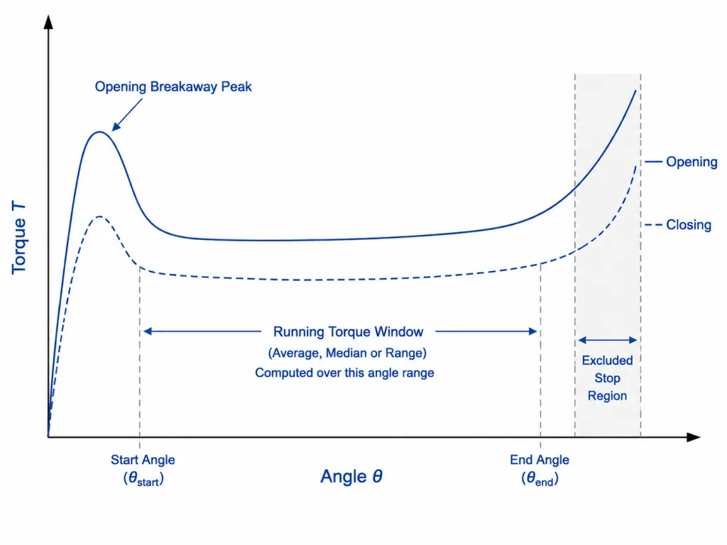
Define the data windows before reviewing the result. For example, breakaway may be the first valid peak after motion begins, while running torque may be the average or median across a stated central angle range. The exact definition is Project-Specific.
Do not include the mechanical end stop in the normal running-torque window. Stop impact measures the stop and fixture load path, not the friction behavior of the hinge.
Measure Static Holding Torque and Drift Separately
Running torque does not automatically prove that a panel will remain stationary. A hinge may move with acceptable resistance and still drift under a sustained external moment. Conversely, a hinge may resist static movement well but have a high starting peak that makes repositioning difficult.
A static holding test should define the hinge angle, direction of the applied moment, external load, dwell duration, allowed angular movement, temperature, and whether the test begins after opening or closing. These details matter because the hinge may settle differently depending on the direction from which the position is approached.
| Static Test Method | What It Measures | Important Control |
|---|---|---|
| Applied torque with no permitted motion | Minimum external torque that the hinge resists at a defined angle | Define the dwell and the angular movement that counts as failure |
| Known panel moment and drift observation | Whether the complete assembly remains inside an allowed angle band | Record panel mass, center of gravity, axis orientation, cables, and approach direction |
| Incremental torque until movement | Static release threshold after a stated dwell | Apply torque gradually and distinguish true movement from fixture compliance |
| Position-hold comparison before and after conditioning | Change in static performance after cycling, temperature, or environment | Use the same angle, direction, load, dwell, and measurement method |
When a force gauge is used, apply the force at the approved perpendicular lever arm and hold it for the defined time. Do not use a brief peak reading as evidence of sustained holding. If the panel is allowed to move slightly, define the maximum angular drift and the observation period.
A loaded-panel test is often the clearest functional evidence, but it represents the complete assembly. A hinge-only static test is better when the drawing needs a component torque limit. Use both when the OEM must approve the hinge and the final equipment behavior.
Do not mix static and dynamic metrics: Breakaway torque, static holding torque, running torque, and panel drift may be related, but none can be substituted for another without a validated correlation.
Standardize Units, Sign Convention, and Reported Precision
Torque data can be misread even when the test itself is sound. State the unit, direction convention, reference view, angle zero, and sign convention on every graph and result table.
| Reporting Field | Recommended Practice | Avoid |
|---|---|---|
| Torque unit | Use one primary unit for the project, normally N·m or N·cm, and identify any converted value | Mixing kgf·cm, lbf·in, N·cm, and N·m without conversion control |
| Direction | Define positive and negative torque from a drawing view or use opening and closing | Writing only clockwise or counterclockwise without a reference side |
| Angle | Define zero position, positive rotation, and the valid measurement range | Assuming every operator uses the same closed position |
| Precision | Report only digits supported by sensor resolution and method capability | Publishing excessive decimal places that imply false accuracy |
| Curve labels | Identify specimen, sweep number, direction, temperature, speed, and date | Saving anonymous curves that cannot be traced to the hinge |
Useful unit relationships include 1 N·m = 100 N·cm, 1 lbf·in ≈ 0.113 N·m, and 1 kgf·cm ≈ 0.0981 N·m. Treat converted values as derived results and retain the original measured unit in the raw record.
For one-way or asymmetric hinges, a signed torque-angle curve can be useful. For production operators, opening and closing labels may be clearer. Choose one convention and apply it consistently across the drawing, fixture, software, report, and acceptance criteria.
Separate Hinge Torque From Complete-Assembly Operating Torque
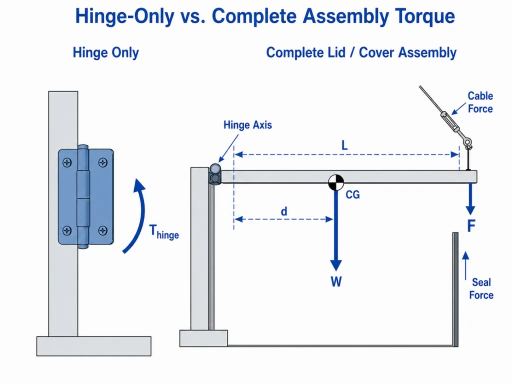
When the hinge is measured on a loaded lid, display, or door, the instrument usually sees more than the hinge. The measured assembly torque can include hinge resistance, gravitational moment, cable force, seal compression, latch interference, bearing friction, and bracket deformation.
Assembly relationship: Tmeasured = Thinge + Tgravity + Tcables/seals + Tother interfaces. The sign of each contribution depends on direction and angle.
| Observed Behavior | Possible Contributor | How to Separate It |
|---|---|---|
| Torque changes strongly with angle | Gravity, cable routing, spring force, or changing seal geometry | Measure the hinge alone or establish a non-hinge baseline |
| Opening and closing curves are offset | Gravity, gasket hysteresis, latch drag, or intentional one-way hinge design | Reverse orientation or remove external contributors one at a time |
| Local peak at one angle | Cable snag, bracket contact, stop interference, or fixture rubbing | Inspect the assembly while reviewing the torque-angle curve |
| Installed torque is higher than bench torque | Axis misalignment, fastener distortion, panel twist, or additional interfaces | Loosen or re-fixture systematically without changing the hinge setting |
| Panel holds even when measured hinge torque appears low | Counterbalance, spring assistance, favorable center-of-gravity position, or multiple hinges | Calculate and measure the complete load path |
Use the complete assembly to verify user effort and panel holding. Use the hinge-only fixture to approve the hinge’s own torque output. Do not subtract a theoretical gravity value without confirming the actual mass, center of gravity, axis orientation, and angle.
Measure Paired or Multiple Torque Hinges as a System
Multiple hinges can be tested individually, together in a common fixture, or on the complete panel. Each method answers a different question.
| Test Configuration | What It Reveals | What It Can Miss |
|---|---|---|
| Each hinge individually | Unit torque, direction, curve shape, and part-to-part variation | Axis mismatch and load sharing in the final panel |
| Matched pair in a rigid fixture | Combined torque and synchronization under controlled geometry | Panel flex, real fasteners, and housing compliance |
| Complete panel assembly | User effort, holding, twist, cable effects, and installed alignment | Individual hinge contribution unless additional measurements are made |
Do not assume the combined torque is exactly the arithmetic sum of two catalog values. Installation tolerance, bracket stiffness, axis error, and different curve shapes can make the pair feel uneven or create local peaks.
If the drawing specifies a total assembly torque, state whether each hinge also has an individual limit. Individual limits help prevent one hinge from carrying most of the resistance while the total still appears acceptable.
Analyze Breakaway, Running, Holding, and Directional Results
| Reported Metric | Recommended Definition in the Test Method | Common Reporting Error |
|---|---|---|
| Breakaway torque | First valid peak after motion starts following the stated dwell | Reporting a fixture impact or data spike |
| Running torque | Average, median, or band over a named angle range at the stated speed | Using the entire arc, including starts and stops |
| Opening/closing difference | Separate curves or calculated difference at matched angles | Combining both directions into one value |
| Torque ripple | Peak-to-peak or other approved variation inside the running window | Calling every angular change a defect without a limit |
| Holding behavior | Drift or static balance under a stated external moment and dwell | Using the running value as automatic proof of static hold |
| Repeatability | Variation between repeated sweeps on one specimen | Mixing within-specimen and part-to-part variation |
| Reproducibility | Variation between operators, fixtures, instruments, or laboratories | Assuming one operator’s repeatability represents the whole method |
Keep the raw torque-angle curves for engineering review. A summary table is useful for approval, but the curve often reveals misalignment, stick-slip, local interference, or direction-dependent behavior that a single number hides.
When smoothing or filtering is used, save the raw data and state the algorithm. Excessive filtering can remove real breakaway peaks or torque ripple, while insufficient sampling can miss them.
Control the Main Sources of Hinge Torque Measurement Error
| Error Source | Effect on Torque Result | Control |
|---|---|---|
| Sensor calibration and zero drift | Constant offset or scale error | Use a suitable calibrated instrument and verify zero before the test |
| Sensor range and resolution | Low readings become noisy or rounded; overload can damage the sensor | Match the range to expected torque and approved overload margin |
| Lever-arm length | Direct proportional error in force-based calculation | Measure the perpendicular distance from the true axis |
| Force angle | Result is overstated if full force is used without the sine correction | Keep the force perpendicular or calculate the geometry |
| Axis misalignment | Adds side load, bearing friction, and false peaks | Use locating features and verify coaxial alignment |
| Fixture compliance or backlash | Delays motion and distorts breakaway | Use a rigid, low-backlash load path and characterize fixture behavior |
| Speed and dwell variation | Changes static and dynamic friction response | Automate movement or use a controlled procedure |
| Temperature | Changes lubricant and friction-material behavior | Condition the specimen and record temperature |
| Data sampling and filtering | Misses peaks or creates artificial smoothness | Define acquisition and processing settings |
| Operator technique | Changes force direction, rate, zero, and chosen peak | Use guides, training, or an automated stand |
A result should not carry more decimal places than the instrument, fixture, geometry, and method can support. Production limits must include practical measurement capability, not only the desired product tolerance.
When the torque tolerance is close to the expected measurement error, improve the fixture and method before tightening the product limit. Otherwise good hinges may fail and bad hinges may pass depending on setup.
Troubleshoot Hinge Torque Test Problems
| Test Problem | Likely Cause | Corrective Action |
|---|---|---|
| Breakaway peak changes every sweep | Dwell varies, fixture slips, hinge is still settling, or zero drifts | Control dwell, inspect adapters, precondition, and re-zero |
| Torque rises near one end of travel | Fixture contact, cable pull, stop engagement, or axis error | Inspect the moving envelope and exclude the stop region |
| Opening result is stable but closing is noisy | Backlash, reversal impact, cable hysteresis, or one-way mechanism behavior | Define reversal procedure and inspect the reverse load path |
| Two operators get different values | Manual speed, force angle, peak selection, or lever position differs | Use guides, automatic movement, and a written data-window rule |
| Direct sensor and lever-arm results disagree | Incorrect radius, force angle, sensor tare, or different test conditions | Reconcile geometry, units, direction, speed, dwell, and specimen state |
| Installed assembly is much stiffer | Bracket distortion, nonparallel axes, fastener preload, seal, cable, or panel twist | Separate the hinge-only and assembly contributors |
| Calculated required torque matches, but panel drifts | Measured metric is not static holding torque or load geometry is wrong | Verify the requirement calculation and conduct a defined holding test |
| Torque drops after adjustment | Setting is not locked, preload settles, or the mechanism was adjusted outside instructions | Follow the model-specific adjustment and recheck procedure |
Measurement troubleshooting should change one variable at a time. Replacing the hinge before checking the fixture can hide a setup problem and create inconsistent conclusions across samples.
Separate Engineering Characterization From Production Torque Checks
An engineering test should reveal the full behavior needed for design approval. A production test should detect unacceptable variation quickly without recreating every characterization step.
| Test Level | Typical Outputs | Required Control |
|---|---|---|
| Engineering characterization | Full opening and closing curves, breakaway, running windows, angular variation, temperature or condition comparisons | Controlled fixture, traceable raw data, defined processing, and complete specimen record |
| Sample approval | Approved metrics on production-intent hinges and the complete assembly | Drawing revision, supplier lot, fixture revision, acceptance bands, and correlation to the application |
| Production screening | Selected torque point, angular window, or go/no-go result | Validated correlation to the engineering method, operator instruction, gauge checks, and reaction plan |
Do not convert a convenient production handle-force check into the engineering definition unless the relationship to hinge torque has been established. A fast test is valuable only when it rejects the same functional problems as the approved method.
For an adjustable hinge, measuring the approved setting does not replace the procedure for changing and securing that setting. Use the separate guide on how to adjust a torque hinge when the measurement result requires correction.
Composite Engineering Scenario: Instrument Access Lid
Engineering example: This is a composite engineering scenario created to explain the measurement logic. It is not a customer project record or product test claim.
An OEM receives two torque-hinge samples with the same nominal rating. Both hold a small instrument access lid, but one feels smooth and the other sticks before moving. The first test uses a handheld force gauge at the lid edge and reports only the maximum force. The results vary because the operator changes the pull angle and speed, and the lid’s center of gravity adds a changing moment.
Engineering separates the questions. The hinge is first measured alone with a coaxial torque sensor. The method defines opening and closing direction, starting angle, dwell, speed, preconditioning, and a central running-torque window. The curve shows that both samples have similar running torque, but one has a higher breakaway peak.
The complete lid is then tested with a guided force gauge at a fixed perpendicular lever arm. This second test includes gravity, cables, bracket stiffness, and the user contact point. The smoother hinge produces the preferred operating feel without reducing the required holding performance.
The approved drawing does not rely on one nominal number. It defines separate breakaway and running limits, direction, angle window, temperature, and the test fixture reference. Production uses a shorter correlated check, while the full torque-angle method remains the engineering reference.
Use the Same Torque Method Before and After Cycle Testing
Torque retention is meaningful only when the before-and-after measurements use the same specimen condition, direction, angle range, speed, dwell, temperature, fixture, data window, and processing rule. Changing the method can look like product decay or hide real decay.
This article does not define the required cycle count or allowable torque change. Those decisions belong to the torque hinge cycle-life and torque-retention guide. The measurement method developed here should be referenced by that life-test plan.
If a hinge is measured hot immediately after rapid cycling, record that condition separately from a stabilized room-temperature result. Both may matter, but they answer different questions.
Hinge Torque Measurement Checklist
HINGE TORQUE MEASUREMENT — TECHNICAL CHECKLIST
------------------------------------------------
MEASUREMENT OBJECTIVE
[ ] Required output identified: holding / breakaway / running / opening / closing
[ ] Hinge-only or complete-assembly result clearly stated
[ ] Peak, average, median, band, or drift definition approved
[ ] Required torque calculation kept separate from measured output

SPECIMEN
[ ] Hinge model, revision, lot, finish, and adjustment state recorded
[ ] Single hinge, matched pair, or complete assembly stated
[ ] Fasteners, brackets, panel, cables, seals, and external load recorded
[ ] Lubrication, cleaning, and preconditioning controlled

INSTRUMENT AND FIXTURE
[ ] Torque sensor or force gauge range is suitable
[ ] Calibration and zero status verified
[ ] Hinge axis and sensor axis aligned
[ ] Fixed side is rigid and moving side cannot slip
[ ] Fixture friction, backlash, and contact are checked
[ ] Lever arm and force angle are defined where used
[ ] Overtravel and mechanical-stop regions are controlled

TEST CONDITIONS
[ ] Opening / closing or CW / CCW reference defined
[ ] Start angle, end angle, and measurement windows stated
[ ] Speed stated
[ ] Dwell time stated
[ ] Preconditioning stated
[ ] Temperature and soak condition stated
[ ] Orientation and gravity direction stated
[ ] Sampling and filtering settings stated

DATA AND ACCEPTANCE
[ ] Raw torque-angle curve retained
[ ] Breakaway definition stated
[ ] Running-torque window stated
[ ] Static holding or drift method stated where required
[ ] Unit, angle zero, and direction convention stated
[ ] Opening and closing reported separately
[ ] Repeatability and part-to-part variation separated
[ ] Invalid peaks and excluded regions documented
[ ] Units and conversions checked
[ ] Acceptance limits include practical measurement capability
[ ] Production screening is correlated to engineering characterization
Frequently Asked Questions
What is the simplest way to measure hinge torque?
Use a force gauge at a known perpendicular lever arm and calculate torque as force multiplied by perpendicular distance. This is suitable only when the force direction, radius, angle, speed, fixture, and specimen condition are controlled.
What is the difference between breakaway torque and running torque?
Breakaway torque is the peak needed to start movement after a defined rest period. Running torque is the resistance after motion begins, evaluated over a stated angular window and speed.
Can I measure hinge torque by pulling on the installed panel?
Yes, but that result represents the complete assembly. It may include gravity, cables, seals, bracket flex, alignment error, and other friction in addition to the hinge.
Why do opening and closing torque measurements differ?
The difference may come from one-way hinge design, gravity, seal hysteresis, cables, fixture backlash, alignment, lubricant behavior, or different test conditions. Measure and report both directions separately.
Should hinge torque be reported as a peak or an average?
Use the metric required by the function. Breakaway is commonly represented by a defined starting peak, while running torque may use an average, median, or band over a named angle range. The method must state the definition.
How do I compare torque measurements from two suppliers?
Confirm that both values use the same torque definition, direction, angular range, speed, dwell, temperature, preconditioning, fixture, data processing, and specimen configuration. Nominal numbers are not comparable when the methods differ.
How should torque be measured before and after cycle testing?
Use the same fixture, direction, angle range, speed, dwell, temperature, specimen orientation, data window, and processing rule before and after cycling. Record hot and stabilized results separately when both are relevant.
Summary: Measure the Curve Under Defined Conditions
The reliable answer to how to measure hinge torque is to define the required output, choose a fixture that does not add uncontrolled load, and control the conditions that change friction behavior. Record the hinge identity, assembly state, direction, angle, speed, dwell, preconditioning, temperature, orientation, instrument, fixture, and data-processing rule.
Use a direct torque sensor for detailed torque-angle characterization or a force gauge with a controlled perpendicular lever arm for suitable checks. Keep hinge-only torque separate from complete-assembly operating torque, and report breakaway, running, opening, closing, holding, and variation only according to written definitions.
| Need a Hinge Torque Measurement Review? | Project Information |
|---|---|
| Engineering input | Send the hinge drawing, torque definition, expected range, direction, angular window, speed, dwell, temperature, specimen configuration, fixture concept, and required acceptance outputs. Contact our engineering team → |