-
+86 13720060320
-
lanna@haitangs.com

360° Swivel Torque Hinge Cable Routing and Rotation Limits
A swivel hinge can turn smoothly through a full revolution on the bench, then pull on its wiring after installation. The hinge has not necessarily changed. The cable now bridges a stationary housing and a rotating component, and that relative movement has to go somewhere.
Swivel torque hinge cable routing must be designed around the permitted motion of the wired assembly. A 360° mechanical travel specification alone does not establish how far that assembly can turn, how often it may reverse, or whether it can keep rotating in one direction.
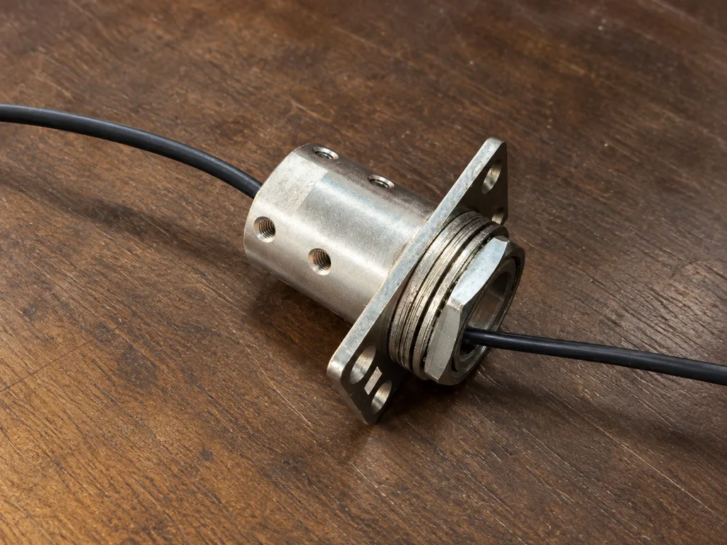
The rotation sequence comes first
Start with what the operator can actually do. A panel that turns toward either side and returns along the same path presents a different cable problem from a fixture that can be turned repeatedly in one direction. Both might appear on a drawing labeled “360° rotation.”
| Required movement | Cable concern | What the design must establish |
|---|---|---|
| Back-and-forth movement within a bounded arc | Repeated bending and torsion between defined endpoints | A controlled assembly reference, permitted travel in each direction, and a cable arrangement qualified for that motion. |
| A full revolution followed by reversal | The wire path must accommodate the complete excursion before it unwinds | The permitted accumulated angle and a means of preventing additional turns. Matching endpoint orientations do not establish matching cable states. |
| Repeated same-direction or continuous rotation | A conventional tethered harness cannot absorb unlimited accumulated twist | A suitable rotary electrical interface or another architecture that removes the unlimited twisting demand. |
Write down direction as well as angle. “Returns to the front” is ambiguous when the operator can reach the front by continuing around the back. Distinguish returning along the same path from completing another revolution.
For continuous rotation with electrical transfer, a slip ring is one possible interface. Moog’s slip ring overview explains how these devices transfer power and signals between stationary and rotating structures. Selection still depends on circuit ratings, data protocol, operating speed, available space, and environment. A swivel torque hinge should not be assumed to include this function.
A finite cable-management arrangement may accommodate a defined number of turns. That remains a bounded system: its allowable travel, reset sequence, and limits need to be specified. “More than one turn” and “unlimited rotation” are different requirements.
A center bore still leaves a twisting span
Routing near the rotation axis can reduce the space swept by the harness. It does not remove relative rotation between the fixed and moving cable ends. Even a cable passing exactly through the axis can twist when its ends are restrained against rotation.
Follow the actual harness from the fixed enclosure to the rotating component. Identify where the jacket is restrained, where the cable can move, and where connectors transfer load into the equipment. The effective twisting span may be much shorter than the total cable length.
- Fixed-side restraint: Show the clamp, gland, or other feature that establishes the stationary end of the moving span.
- Moving-side restraint: Show which attachment rotates with the component and whether the connector is isolated from cable movement.
- Intermediate contacts: Include sleeves, guides, ties, and bore edges that can restrict movement or concentrate twist.
- Assembly path: Check whether the terminated connector can pass through the available opening, or whether the assembly sequence requires a different connection arrangement.
An opening large enough for the cable jacket may still be too small for its connector or protective sleeve. A larger hole also does not guarantee a suitable exit path. The cable can leave the bore at a sharp angle and bend repeatedly at the same short section.
If the movement is mainly a cabinet-door harness sweeping through an opening arc, use the separate control-panel door hinge and cable-clearance guide. For axial swivel motion, the additional question is how rotation is distributed through the restrained cable span.
Set the assembly reference before routing
The operating zero and the cable’s neutral installation condition must be related on the assembly drawing. They are not automatically the same. A display may need an asymmetric working arc, or its preferred viewing position may sit away from the midpoint of travel.
Define the viewing direction used for clockwise and counterclockwise movement. Then show the reference orientation of the fixed housing, rotating member, and cable restraints. Document any intended cable pre-twist; otherwise, an assembler can install an apparently correct harness with part of its available travel already consumed.
The panel faces forward. The cable may already be wound. Consider a hypothetical display with no effective rotation stop. An installer connects the harness in its intended neutral condition. During setup, the display is moved through four successive clockwise quarter-turns. It faces forward again, but the fixed-to-moving cable connection has accumulated one full turn. A check based only on the display’s final orientation misses that change. Later counterclockwise movement may unwind the gross rotation, but it does not establish that the cable avoided damaging local strain along the way. These angles illustrate rotation history; they are not recommended cable limits.
This is an illustrative engineering scenario, not a customer project record or product test claim.
Assembly marks can help reproduce the intended clocking, provided the instructions also establish the cable’s untwisted starting condition. Matching marks alone cannot reveal an extra full turn hidden in the harness. Service instructions should preserve the same reference when a panel or harness is replaced.
Cable ratings need their test conditions
A flexible cable is not automatically a torsion-rated cable. Repeated bending, twisting about the cable axis, and a combination of both place different demands on the conductors, shielding, jacket, and terminations.
Obtain the data for the exact cable construction. Relevant information includes its permitted torsion under the supplier’s stated conditions, dynamic bend radius, moving-use temperature range, and test motion. LAPP’s ROBOT 909 technical data, for example, lists torsion separately from fixed-installation and flexible-use bend radii. Those distinctions matter; the values belong to that cable, not to every harness routed through a swivel hinge.
When a torsion rating is expressed as angle per unit length, do not substitute the total harness length. Only the span actually available to accommodate the motion is relevant, and twist may not distribute uniformly through it. A nearby clamp, tight sleeve, or contact with an exit edge can concentrate movement. Ask the cable supplier to review the proposed restraint spacing and combined bending-and-torsion path.
Test conditions also limit what a published cycle result establishes. The igus explanation of robotic cable torsion testing describes defined restraint spacing and rotational excursions. A result from that arrangement does not, by itself, qualify a shorter or differently restrained harness in a compact swivel mount.
Review the complete bundle. A power cable, shielded data cable, and protective bonding conductor can have different constructions and movement limits. Adding a sleeve or tightening the bundle can change how those elements move together. Where a second tilt axis shares the harness, include the combined positions rather than checking each axis in isolation.
Put the stop inside the cable’s working range
The permitted swivel range must satisfy the harness limits as well as the hinge travel and surrounding geometry. Establish the clockwise and counterclockwise endpoints from the documented assembly reference. They need not be symmetric.
The designated stop must arrest movement before the cable becomes taut, exceeds its qualified twisting condition, or loads a connector unacceptably. Include assembly clocking variation, restraint-location tolerances, and any movement beyond first stop contact. There is no universal number of degrees to subtract from the catalog travel.
Holding torque is not a rotation stop. Friction may resist movement while still allowing the operator to continue turning. If the hinge includes a stop, obtain confirmation that it is intended for the assembly’s stopping duty. Structural stop loading and overtravel are covered in the industrial opening-stop design guide.
An angle label or operating instruction does not physically prevent another turn. Where cable protection depends on a restricted range, the equipment design needs an effective means of enforcing that range under its intended use and service conditions.
Watch what the finished harness does
Install the actual cable types, connectors, sleeve, and restraints before judging swivel feel. Cable reaction can help movement in one direction and oppose it in the other. A dry hinge test will not reveal that contribution.
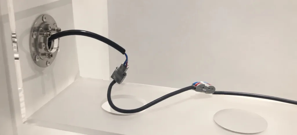
Look for changes tied to position or motion history:
- Increasing effort near one endpoint can indicate that twist or tension is accumulating in a short span.
- Movement back toward a preferred position after release can indicate cable restoring torque; other assembly loads must also be considered.
- A sudden catch, connector movement, or a shifting loop points to a routing interaction that a single average torque value can conceal.
These observations guide investigation; none identifies the cause on its own. Compare controlled sweeps with and without the harness contribution where the test arrangement permits it, keeping support geometry and other loads consistent. Use the hinge torque measurement method to define direction, speed, dwell, and the reported quantity.
Increasing hinge torque may suppress visible springback while leaving excessive cable strain unchanged. Correct the routing or motion limit before using a higher torque setting to compensate for it.
Validate the actual adjustment sequence
A repeated left-right sweep proves only the behavior of that sequence. It can miss what happens when a user makes several adjustments in the same direction, reaches a service position, or reconnects the harness at a different orientation.
Test the finished arrangement with its covers, restraints, and connectors in their intended locations. Where direct viewing is obstructed, choose an observation method that preserves the routing geometry. Removing a cover that guides the harness can change the result.
| Test condition | Evidence to record | What it can reveal |
|---|---|---|
| Travel to both limits, including intermediate positions | Cable path, local bends, connector movement, operating effort, and peak travel | A local restriction or overtravel that endpoint photographs alone miss. |
| Successive same-direction adjustments allowed by the design | Accumulated angle, stop behavior, and changes in harness shape | Whether the allowed sequence can consume more cable travel than the nominal working arc suggests. |
| Repeated operation under the specified environment | Motion sequence, temperature, cycling conditions, electrical performance, and post-test condition | Progressive mechanical or electrical change under the project’s actual duty. |
| The defined replacement or service sequence | Cable reference condition, restraint locations, and available travel after reassembly | Whether servicing can introduce pre-twist or alter the moving span. |
Define acceptance criteria before cycling: permitted movement effort and position recovery, electrical or data performance, connector retention, and allowable cable condition. The cycle target, speed, dwell, and temperature must come from the intended duty and supplier evidence. A hinge-only durability result does not establish harness life.
Monitor relevant electrical functions during motion when intermittent faults are a concern. A continuity check performed only at rest may miss a position-dependent interruption, and continuity alone does not establish the performance of a data link. Use the electrical checks appropriate to the installed circuits.
A change to cable construction, active length, connector orientation, restraints, or sleeve should trigger a review of the affected evidence. The same hinge part number does not make those harness configurations equivalent.
Put swivel torque hinge cable routing on the drawing
The drawing should let another assembler reproduce the motion you validated. A routing sketch and a short set of controlled notes are usually more useful than “allow cable slack.” Include:
- Motion reference: Axis, viewing direction, assembly zero, permitted travel in each direction, and whether additional same-direction turns are prevented.
- Harness arrangement: Cable and connector identifiers, fixed and moving restraints, active span, routing envelope, and intended installation condition.
- Travel control: Stop locations and permitted variation, with the maximum assembly travel kept within the reviewed harness limits.
- Supporting evidence: The applicable cable data and assembly test reference, including the motion and service sequences used.
With these requirements defined, review the available 360° swivel torque hinges for mounting geometry, cable-passage availability, torque behavior, and travel configuration. Confirm those features on the selected model’s drawing; they should not be inferred from the category name.
For a model inquiry, attach the marked routing sketch and state whether the assembly needs bounded repositioning or continuous rotation. Ask for the candidate model’s drawing and confirmation of its relevant features. This gives the supplier a concrete interface to compare while keeping cable suitability tied to the specified harness and assembly evidence.
Cable routing and rotation limit FAQ
Can a 360° swivel torque hinge rotate continuously with wires attached?
Only if the complete electrical and mechanical arrangement supports it. A conventional harness bridging fixed and rotating components has a finite movement capacity. Continuous same-direction rotation generally requires a suitable rotary electrical interface or another architecture that avoids unlimited cable twist.
Does a center cable hole prevent wire twisting?
No. It provides a routing passage and may reduce the harness sweep, but the cable can still twist between restrained ends. Passage geometry, effective moving length, cable construction, and rotation history determine the installed behavior.
How many turns can a torsion-rated cable tolerate?
There is no universal turn count. Use the exact cable supplier’s conditions for torsion, active length, bending, temperature, and repeated motion. A permitted angular excursion and a fatigue cycle rating describe different limits; neither means the cable can accumulate unlimited turns.
Will reversing the swivel remove cable fatigue?
Reversing along the same path can reduce accumulated twist, but it does not reverse wear or fatigue already caused by movement. The cable still needs qualification for the repeated excursion and its actual restraint arrangement.
Should the cable be neutral at the midpoint of travel?
That can be useful for a symmetric motion range, but it is not a universal rule. The required working arc, routing geometry, and supplier limits may call for another installation orientation. Specify the chosen reference and any intended pre-twist so production and service reproduce it.
Can extra cable length replace a rotation stop?
No. Additional usable length may help a bounded routing arrangement, but unmanaged slack can snag or concentrate bending. It does not permit indefinite same-direction rotation. If the assembly relies on a finite cable travel limit, that limit still needs to be enforced.