-
+86 13720060320
-
lanna@haitangs.com

Hinge Static Load Testing: Proof Load, Permanent Set and Acceptance Criteria
A hinge can survive a high static force and still be unsuitable for the application. The leaf may take a permanent set. Mounting holes may slip. A pin or retainer may move. The assembly may return close to its original position but bind when the door is opened again. None of those outcomes can be judged from a catalog statement such as “80 kg load” unless the test geometry and acceptance rule are also known.
Hinge static load testing turns that vague capacity number into a repeatable engineering test. The work starts with the real load path: hinge quantity, spacing, orientation, mounting structure, force direction, and distance from the hinge axis. Only then should a proof load be applied. The result is not simply “did it break?” It includes movement under load, residual deformation after unloading, physical damage, mounting integrity, and post-load function.
Start with the setup, not the load number. Define the fixture, load direction, load point, hinge arrangement, measurement datum, unloading condition, and acceptance limit before writing the proof-load value. Without those fields, a hinge load rating test is difficult to reproduce or compare within a load validation and quality testing program.
Hinge Static Load Test Geometry
Two hinge suppliers can publish the same nominal capacity and still be describing very different tests. One result may come from a single hinge clamped between rigid steel plates. Another may describe two hinges supporting a door-sized fixture. The force may act close to the pin centerline, at the edge of a long test arm, vertically downward, perpendicular to the leaves, or along another axis entirely.
Those differences change the load carried by the leaf, knuckle, pin, fasteners, and mounting structure. They also change the bending moment delivered to the joint. Before comparing any published load value, identify:
- number of hinges in the test;
- distance between hinges when more than one is used;
- hinge orientation and opening position;
- force direction relative to the pin axis and mounting planes;
- distance from the applied force to the relevant hinge axis or support datum;
- mounting substrate and reinforcement;
- fastener or weld configuration;
- whether the result is a proof load, failure load, or recommended working condition;
- what constituted failure.
A catalog value written in kilograms needs the same scrutiny. Determine whether it represents the mass of a particular door configuration, an equivalent force under a stated setup, or simply a commercial capacity label. The hinge spec sheet and engineering drawing guide covers how to identify these missing conditions before accepting supplier performance data.
What the Static Test Must Prove
“Check hinge strength” is not a complete test objective. A useful hinge strength test translates strength into structural, dimensional, and functional limits that can actually be measured.
A useful static-load test should answer four questions:
- Did the defined hinge and mounting arrangement withstand the proof condition?
- How far did the selected measurement point move while the load was applied?
- How much movement remained after unloading?
- Did the hinge and mounting system still perform the required function afterward?
These questions also define the boundary of the test. Static proof loading does not establish cycle life, long-term wear, vibration durability, impact resistance, corrosion behavior, or temperature-cycle performance unless those conditions are separately included and controlled.
For builders hardware within its scope, ANSI/BHMA A156.1-2025 for Butts and Hinges includes strength, cycle, wear, friction, material, and dimensional requirements. That makes it a useful reference when the hinge and application fall within the standard’s scope. It should not be treated as a universal industrial-equipment hinge qualification method.
Machine guards, electrical enclosures, instrument panels, service doors, and other equipment hinges may require project-specific load direction, mounting geometry, proof condition, and pass/fail criteria even when an external standard is used as a reference.
Service, Proof, and Ultimate Load
These three terms describe different conditions.
Service load is the defined load the assembly is expected to experience in use. It may include panel weight, an external operating force, mounted equipment, or another project-specific action. Its direction and lever arm are part of the definition.
Proof load is a verification load applied to determine whether the defined assembly remains within predetermined limits. When a project uses a proof load factor, that factor should come from the governing requirement, customer specification, risk assessment, applicable standard, or validated design rule rather than from a universal multiplier.
Ultimate or failure load is different again. The specimen is loaded until a defined failure event occurs or the planned test limit is reached. That may be useful for characterization, but it can permanently damage the specimen. A hinge taken toward failure should not later be treated as an untouched proof-qualified sample.
kp = Fproof / Fservice
This ratio is meaningful only when the service and proof conditions use comparable force direction and geometry. If the structural requirement is defined by moment instead of direct force, compare the corresponding moments.
An arbitrary “1.5×” or “2×” multiplier can be misleading. A larger direct force applied close to the pin may create less bending demand on one feature than a smaller force acting through a long lever arm. The proof condition has to represent the structural question the test is intended to answer.
Reproduce the Real Load Path
The hinge does not experience “door weight” as one isolated number. The load enters through the moving panel, passes through the hinge leaves and pivot, and returns through fasteners, welds, reinforcement, and the fixed frame. The test fixture should preserve the portion of that load path the qualification is intended to evaluate.
For a force applied at a perpendicular distance from the hinge reference axis, the first-order moment relationship is:
Mtest = Ftest × L⊥
Ftest = Mtarget / L⊥
Ftest is the applied force and L⊥ is the perpendicular distance from its line of action to the chosen reference axis. The second form can be used when a target moment is known and a fixture lever arm has already been selected.
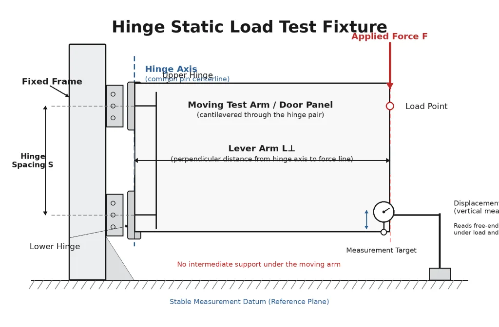
These equations do not calculate how reactions divide across a multi-hinge door. Two or three hinges do not automatically share load equally. Hinge spacing, mounting stiffness, tolerance, door deflection, and axis alignment influence the actual reactions. If the project still needs to determine door moment, hinge count, spacing, or reinforcement, use the heavy enclosure door hinge load and spacing guide before defining the proof fixture.
The static test should state the force vector instead of relying on labels such as “vertical load” or “side load.” A downward force at the free edge of a side-hinged door is different from a direct tensile force through the hinge centerline. A pull normal to the door skin is different again. Each path stresses a different combination of hinge and mounting features.
The force number alone can rank two tests in the wrong order. A hinge may survive a large direct force near the pin yet deform in a door where a smaller force acts through a much longer lever arm.
Fixture Stiffness and Mounting Interfaces
A test fixture can make a hinge appear either stronger or weaker than it will behave in the final equipment. The question is not whether the fixture is rigid. It is what the fixture is intended to represent.
| Fixture Approach | Useful For | Main Limitation |
|---|---|---|
| Rigid component fixture | Comparing hinge revisions, materials, pin designs, or supplier samples on a controlled basis | Can hide deformation or slip that would occur in thin sheet metal, flexible brackets, formed returns, or production fasteners |
| Production-intent assembly fixture | Evaluating the hinge together with door edge, frame, reinforcement, fasteners, welds, bracket geometry, and hinge spacing | Measured displacement includes the behavior of the complete assembly rather than isolating the hinge alone |
Neither fixture is automatically better. A rigid fixture can make supplier-to-supplier component comparison cleaner. A production-intent structure becomes more important when the actual risk is pull-through, local sheet deformation, hole elongation, bracket rotation, weld movement, or fastener slip.
The mounting condition should record leaf orientation, hole pattern, fastener type, washer or backing arrangement, tightening condition, weld condition where applicable, slot position, shim stack, and reinforcement. Fixed and moving members also need controlled datums so their relative position can be reproduced.
Fixture stiffness matters when displacement is part of acceptance. A dial indicator at the end of a flexible test arm may report fixture bending, mounting movement, and hinge deformation together. That can be correct for an assembly-level requirement, but it is not automatically a component permanent-set measurement.
When a Rigid Fixture Hides the Failure
Thin sheet metal can dimple around fasteners. A formed frame return can rotate. Slotted holes can move to the end of their adjustment range. A welded bracket can distort while the hinge itself remains intact. Replacing that structure with thick laboratory plates removes these failure paths.
Suppose two suppliers report the same static-load result. One tested a single hinge between thick plates with the force close to the pin. The other tested two hinges on a door-like arm using production fasteners and the intended mounting section. The numbers look comparable. The load paths are not.
The first setup may be better for isolating component strength; the second may better represent the installed assembly. High-risk applications can justify both: a controlled component test for comparison and a production-intent assembly test before final release.
If the project is still selecting the hinge architecture instead of validating a defined candidate, review the available industrial hinge range first. Static testing should confirm a defined hinge and load case rather than replace the selection process.
Deflection Is Not Permanent Set
A hinge can move noticeably under proof load and return close to its starting position. Another can appear relatively stiff at peak load but remain displaced after unloading. Those are different behaviors and should not be reported under one “deformation” value.
Choose a stable datum on the fixture or assembly and a moving target that relates directly to the requirement. Record its baseline position, its position at proof load, and its position after unloading.
δload = xproof − xinitial
δperm = xafter − xinitial
δload is displacement while the specified load is present. δperm is the movement that remains after unloading and returning to the same defined reading condition.
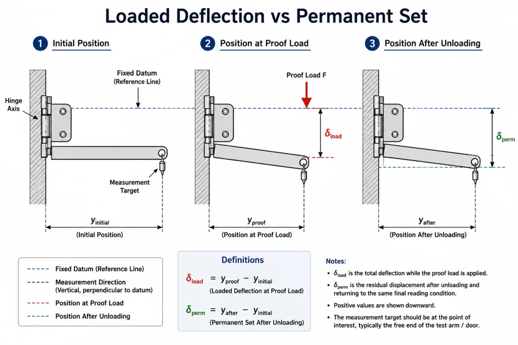
Permanent set may also be described as residual deformation when the measured assembly does not fully return to its initial geometry. If acceptance is based on magnitude rather than direction, state that explicitly—for example, |δperm| ≤ δlimit. The allowable limit remains project-specific unless a governing specification defines it.
Where fixture compliance is significant, additional measurement points can help separate support-frame movement from movement at the hinge or mounting joint. Do not subtract fixture deflection mathematically unless the correction method and measurement model have been established in advance.
The same principle applies to a complete door. Free-edge sag may be the correct system measurement even though it contains leaf bending, hinge-axis movement, and mounting deformation. Describe what the reading represents instead of labeling every displacement “hinge deformation.”
Run the Load as a Controlled Event
A static test should not accidentally become an impact test. Dropping a mass onto the fixture, snapping an actuator into load, or allowing a long test arm to bounce can create transient forces that are not represented by the nominal static value.
- Identify and inspect the specimen. Record the part number, drawing revision, configuration, visible defects, and mounting hardware.
- Install the hinge to the defined fixture condition. Use the specified orientation, hinge count, spacing, fastener condition, shim position, and assembly sequence.
- Establish the measurement baseline. Zero or record displacement instruments at the stated starting position and load condition.
- Apply force gradually. Increase load in the defined direction without impact and record the required force and displacement points.
- Reach the proof condition. Hold the load only for the duration defined by the test specification. There is no universal dwell time for every industrial hinge test.
- Unload in a controlled manner. Return the assembly to the same final reading condition used for the baseline.
- Measure and inspect again. Record permanent set, cracks, slip, hole movement, pin or retainer migration, mounting deformation, and post-load function.
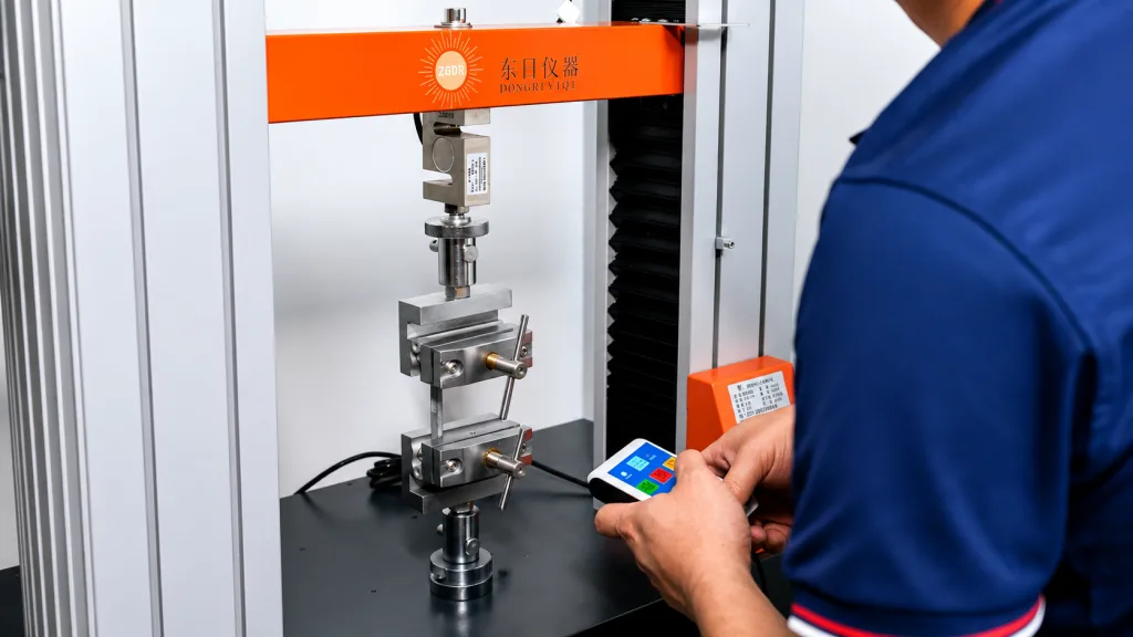
A controlled load test requires a defined fixture, verified force measurement, and repeatable loading condition.
Force Verification Is Not Hinge Acceptance
ASTM E4-24, Standard Practices for Force Calibration and Verification of Testing Machines, covers force calibration and verification for static or quasi-static tension and compression testing machines. It helps establish confidence that the force reported by the machine is traceable and properly verified.
ASTM E4 does not define the hinge fixture, lever arm, proof factor, load direction, dwell time, permanent-set limit, or post-load functional requirement. A calibrated test machine can apply an accurately measured force to a poorly defined hinge test. The product test specification still has to define what that force means.
The displacement measurement deserves the same discipline. Instrument resolution should be appropriate for the acceptance band, the sensing direction should match the intended displacement, and the reference should remain stable relative to the feature being evaluated. More decimal places do not compensate for a measurement system that cannot resolve the pass/fail boundary.
Write Pass/Fail Before Loading
“No breakage” is rarely enough for an industrial hinge proof-load test. A hinge can remain attached while losing the geometry or movement the equipment requires.
| Acceptance Item | What to Define | Evidence After the Test |
|---|---|---|
| Structural integrity | Whether cracks, separation, fracture, pin loss, retainer failure, or another structural event is permitted | Visual inspection and photographs of critical areas |
| Permanent set | Measurement datum, target, direction, final reading condition, and allowable residual movement | Before/after displacement record |
| Mounting integrity | Allowable fastener slip, hole elongation, weld movement, bracket rotation, or substrate deformation | Witness marks, dimensional readings, and joint inspection |
| Pivot condition | Allowable pin migration, knuckle distortion, bushing damage, axial movement, or new contact | Visual and dimensional inspection where required |
| Post-load operation | Required opening range, freedom from binding, closing position, torque, latch alignment, or another application-specific function | Functional check under a defined repeatable condition |
The allowable limit should follow the actual risk. A residual movement that has no effect on one service cover may be enough to shift a precision latch, gasket line, sensor target, or adjacent panel out of position on another assembly.
Likewise, “smooth operation after test” needs a reference when function matters. State the angle range, orientation, attached load, latch state, or other condition that changes the movement. A hinge that feels free after being removed from the fixture may still bind when the permanently shifted mounting structure is left in place.
Set the acceptance criteria before seeing the result. Permanent-set limits, prohibited damage, post-load function, and the treatment of mounting deformation should not be negotiated after the specimen has been loaded.
The Report Must Recreate the Test
A photograph of a weight hanging from a door proves that something was loaded. It does not make the result reproducible.
The report should contain enough mechanical detail for another engineer or laboratory to reconstruct the important test conditions without guessing.
| Report Field | What Should Be Recorded |
|---|---|
| Specimen identity | Part number, revision, material or finish where relevant, sample identification, and test date |
| Fixture | Fixture drawing or controlled sketch, fixed and moving datums, support geometry, and fixture revision |
| Hinge arrangement | Quantity, spacing, orientation, opening position, handing where relevant, and pin-axis direction |
| Mounting | Substrate, reinforcement, fasteners or weld condition, shim or slot position, and critical assembly instructions |
| Load geometry | Force direction, load point, perpendicular lever arm, and whether the requirement is force- or moment-based |
| Load sequence | Starting condition, application method, control mode or rate where specified, proof value, dwell where applicable, and unloading method |
| Instrumentation | Force-measurement system, displacement instruments, measurement locations, calibration status, and relevant resolution |
| Results | Peak force, loaded displacement, final displacement, permanent set, visible damage, mounting movement, and post-load function |
| Acceptance | Each predetermined limit and the corresponding result |
If the fixture or specimen changes, the report should say so. A result obtained with a thick prototype bracket should not quietly become evidence for a thinner production bracket. Changes to hinge spacing, fastener engagement, reinforcement, load point, or door geometry can alter the load path enough that the original result no longer represents the released assembly.
This type of report supports engineering validation. Routine shipment inspection is a different task. Once production parts arrive, dimensional sampling, material and finish checks, defect classification, and lot acceptance belong in the separate industrial hinge quality inspection checklist.
Static Strength Is Not Durability
A proof-load test describes what happened during one controlled static or quasi-static loading event. It does not establish how the pivot, friction surfaces, bushings, fasteners, or mounting structure will change after repeated motion.
The reverse is also true. A hinge can complete many cycles at a modest load without demonstrating the required one-time proof-load capacity. Static strength and cyclic durability require different acceptance questions.
For torque hinges, repeated cycling is especially dependent on torque retention and defined operating conditions rather than simple structural survival. Use the torque hinge cycle-life guide when the engineering question moves from static proof loading to long-term positioning performance.
Impact, vibration, corrosion, temperature cycling, and other service conditions also remain separate unless they are deliberately included in the test program. A passing hinge static load test should be reported for exactly what it demonstrates.
Hinge Static Load Testing FAQ
What is a hinge proof load?
A hinge proof load is a defined verification load applied to a specified hinge and mounting configuration to determine whether it remains within predetermined structural, dimensional, and functional limits. The load value is not meaningful by itself; force direction, load point, hinge arrangement, fixture, and acceptance criteria also need to be stated.
Should a hinge proof test always use twice the rated load?
No. There is no universal 2× proof factor for every industrial hinge and application. The proof factor should come from an applicable standard, customer requirement, project risk assessment, or validated design rule. Lever arm, load direction, hinge spacing, and mounting structure also affect the severity of the test.
How is permanent set measured after a hinge static load test?
Measure a defined moving target from a stable datum before loading, then measure the same target after the proof load has been removed and the assembly has returned to the specified final reading condition. Permanent set is the residual difference between the initial and final positions. The measurement point, direction, unloading condition, and allowable limit should be defined before testing.
Does passing a static load test prove hinge cycle life?
No. Static load testing evaluates the response to a defined static or quasi-static loading event. Cycle-life testing evaluates change after repeated motion. A hinge can pass one and fail the other, so proof load and durability should have separate test conditions and acceptance criteria.
Send the Load Case and Mounting Drawing
When requesting an HSP hinge review for an equipment door, enclosure, access panel, guard, or similar industrial assembly, provide the panel or door data, hinge quantity and spacing, mounting section, load direction, relevant lever arm, and proposed proof condition.
These inputs allow the available hinge configuration to be compared with the actual load case before sample testing. Final proof-load limits and acceptance criteria should remain tied to the released assembly and the agreed test method.