-
+86 13720060320
-
lanna@haitangs.com

How to Choose a Hinge Pin Retention Method for Vibration Equipment
A hinge pin does not have to fall out before retention becomes a problem. Partial axial migration can reduce engagement with one knuckle, increase projection at the opposite end, move a groove or threaded section toward the working bearing area, or change how the pin is supported through the hinge stack.
That makes the choice of a hinge pin retention method more than a question of whether the pin feels tight during assembly. For vibration equipment, the useful questions are what can make the pin move, what physically stops that movement, how much travel exists before the stop is reached, and whether the same retention method still works after the hinge is installed inside the finished equipment.
Two decisions narrow the field quickly. First, decide whether the project needs a positive geometric stop or can accept retention that depends on a controlled friction fit. Then decide whether pin removal is part of normal service. Those decisions usually matter more than the commercial name applied to the retainer.
Pin retention is also different from door anti-lift. A pin can be correctly retained while a removable door still has an unintended lift-off path. Applications using removable hinges should treat lift-off clearance and anti-lift retention as a separate door-level requirement.
Pin Migration Is an Axial Restraint Problem
A hinge normally needs some freedom within the pin-and-knuckle stack so that the leaves can rotate without being clamped axially. That freedom is not automatically a failure. It becomes a retention problem when the pin can continue moving far enough to change the intended support or operating geometry.
Complete pin loss is only the last state in that sequence. If part of the pin withdraws from one knuckle, the supported length and load distribution through the remaining knuckles change. Local edge loading or pin bending demand can increase before the pin is anywhere near falling free.
The opposite end changes at the same time. Additional projection may interfere with a cover, cable tray, guard or adjacent structure. A retaining-ring groove, thread or cross-hole that originally sat outside the working bearing area can also move closer to a knuckle edge.
The release path has two directions
A vertical pin can look secure because gravity favors one direction, but gravity is not a positive retention feature. The equipment may be transported on another face, exposed to shock along the hinge axis, or installed at an angle.
A retaining ring at one end blocks travel toward that ring. The opposite direction still needs a head, shoulder, second retainer, stepped geometry or another trapped feature if the pin is capable of moving that way.
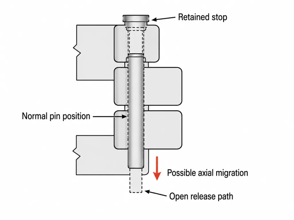
Tracing the pin from one end to the other is more useful than asking whether the drawing contains a retainer. The review is complete only when the feature that arrests each relevant release direction can be identified.
Hinge Pin Retention Methods Differ by Load Path
The largest technical difference is between a positive geometric stop and a friction-dependent joint.
A positive stop prevents additional travel because the retained feature cannot pass through the available opening. A formed head, retaining ring, cross-pin or captured shoulder works this way. Further movement requires the stop, pin, groove or surrounding feature to deform, fracture or disengage.
A friction-dependent system resists movement through contact pressure. An interference-fit pin is the common example. A set screw bearing against a smooth pin can also depend primarily on contact force and friction. There may be no positive feature waiting farther along the release path.
Both approaches can be valid. They simply require different evidence. A formed end can be reviewed through its geometry and assembled condition. An interference fit depends much more heavily on the finished pin, bore and assembly relationship.
“Pin secured” is not a comparable specification. One supplier may mean a swaged end that physically blocks escape. Another may mean an interference fit between the pin and one knuckle. Both can use the same short description while relying on completely different retention mechanisms.
The consequence of migration should influence how much uncertainty the design can tolerate. If limited movement has little effect on the equipment, a properly controlled friction-dependent system may remain reasonable. If migration reduces required knuckle engagement, changes latch or seal position, or can progress toward loss of the door-supporting geometry, positive retention becomes easier to justify.
Interference-fit retention depends on the installed fit
An interference-fit pin can provide substantial axial resistance without an added end feature, but the installed condition is the retention system.
Pin diameter, bore size, roundness, surface condition, coating thickness, knuckle stiffness and assembly method all influence that interface. Nominal pin diameter alone cannot describe the retention condition. A formed sheet-metal knuckle and a thick machined boss can also respond differently to the same nominal interference.
Fretting, corrosion, wear or repeated pin removal can alter the fitted interface during service. This does not make interference retention unsuitable for vibration equipment. It means the supplier should be able to explain what controls the fit and what evidence supports relying on it for axial retention.
A set screw should be reviewed the same way. A screw pressing against a smooth cylindrical pin still depends largely on contact and locking conditions. A screw that enters a dedicated circumferential groove, hole or shoulder can provide a more positive barrier to axial translation. Similar-looking hardware can therefore produce different retention behavior.
Axial Travel Can Turn the Retainer Into an Impact Stop
A positive stop does not always carry load continuously. The pin may have axial freedom between its two restraints and move before it contacts the retained end.
That changes the condition at the stop. A retainer held against a surface with light continuous contact is not loaded the same way as one that is repeatedly struck after the pin moves through a clearance. Under vibration or shock, the second condition can produce repeated local contact at a retaining-ring groove, formed head, cross-pin or adjacent knuckle face.
The resulting load cannot be reduced to one universal force because it depends on the equipment vibration input, moving mass, available axial travel, relative velocity, contact stiffness and local deformation. What matters for selection is the relationship: more axial freedom can change the retainer from a migration backstop into part of the recurring operating load path.
A retention feature can therefore remain present and still be degrading. A ring may still be installed while its groove develops local peening. A formed pin end may remain intact while repeated contact marks the adjacent knuckle face. A cross-pin may remain captured while local deformation develops around its hole.
When the intended design allows the pin to contact the restraint repeatedly, the supplier proposal should address that operating condition rather than only showing that complete pin escape is impossible.
Permanent and Removable Retention Solve Different Service Problems
A pin intended to remain in the hinge for the life of the assembly does not need the same retention architecture as a pin removed during cleaning, repair or scheduled overhaul.
Formed, staked and swaged pin ends
Staking, swaging, spinning, peening or another forming operation changes the end geometry after the pin is assembled. The enlarged or deformed end can no longer pass through the adjacent opening.
This removes the need for a separate clip or nut, which is useful when the pin should never be removed during normal service. The manufacturing operation itself becomes important, however. Too much forming can clamp the knuckle stack or distort the pin. Too little can leave an inconsistent retaining feature.
Pin material and condition matter here. The selected material, hardness and forming process have to be compatible. A retention concept that depends on plastically forming the pin end should not be approved solely from a finished outline without understanding how that geometry is produced.
The best first-party evidence for this type of construction is simple: a close-up photograph of the actual retained pin end together with the corresponding production drawing or sample. That shows the real geometry much better than another generic retention illustration.
Captive pins
A headed pin, trapped shoulder or assembly sequence that closes the release path can produce permanent positive retention without a separate end retainer.
The service trade-off is less visible. If the pin can only be installed before another hinge component is formed, welded or joined, pin damage may require complete-hinge replacement. “Captive” describes the retained condition; it does not automatically mean the pin is conveniently serviceable.
Retaining rings, threaded retainers and cross-pins
Service-removable retainers make sense when pin removal is an intended maintenance operation.
A retaining ring gives a visible positive stop and can allow quick disassembly, but the groove becomes part of the pin geometry. The groove should remain outside an unsuitable bearing region, and sufficient end access is needed for both the ring and the removal tool.
Threaded retention can use a nut, threaded pin end or secured fastener. It is convenient when normal hand tools are already part of the service procedure, but the thread itself does not define how loosening under vibration is prevented. The locking method is part of the proposal.
A cross-pin or cotter creates an obvious physical stop. It also requires a transverse hole in the main pin and adds another service component. The hole position, pin projection and surrounding clearance therefore matter alongside the convenience of removal.
A pin removed regularly needs a retention system intended for repeated service. Permanent end forming usually works against that requirement. The reverse is also true: adding a machined groove, separate ring and replacement-service part to a pin that should never be removed may add manufacturing and maintenance complexity without solving a useful problem.
Axial retention does not define pin rotation
A retained pin can still rotate.
Some hinges intentionally fix the pin to one leaf so rotation occurs between the pin and the opposite knuckles. Others allow the pin to rotate through more of the stack. A retaining ring can control axial escape without controlling either condition.
If the intended stationary interface is not maintained, the active wear surface can move to another pin-to-knuckle interface even while axial retention remains fully intact. A supplier comparison should therefore identify which interface is expected to rotate, not only what keeps the pin from leaving the hinge.
Retention Geometry Must Stay Out of the Bearing Problem
Positive retention often adds a groove, hole, thread or formed transition to the pin. Those features should be reviewed together with the regions where the pin is supported.
A retaining-ring groove reduces the local pin section. A cross-hole interrupts the section in another way. Thread runout and abrupt formed transitions also change local geometry. Locating those features immediately beside a heavily loaded knuckle edge can concentrate two different functions—bearing support and retention—into the same short section of pin.
Axial movement can make this worse. A groove that begins outside the bearing area can move toward the edge of a knuckle. A threaded portion can enter a region intended for smooth sliding contact. A cross-hole can move closer to a highly loaded support point.
The useful review combines three pieces of geometry: where the pin is supported, where the retention feature sits, and how far the pin can move before the stop is reached.
A correctly installed retainer can still sit in the wrong architecture. A ring may be fully seated in its groove, yet the groove can still be poorly located if normal axial movement carries it into the working bearing zone.
The Installed Machine Can Reject a Good Retainer
A retention method can look completely reasonable on the hinge drawing and become difficult to use after the rest of the machine is assembled.
Retaining rings need plier access. Threaded retainers need a wrench, socket or driver. Cross-pins need space for the secondary pin to be withdrawn. After the retainer is released, the main hinge pin may still require axial travel before it clears the knuckle stack.
The relevant service clearance is therefore the complete envelope of the retainer, tool and pin-removal motion—not merely the visible gap next to the hinge.
Secure in operation, blocked during service
A retaining ring above the upper knuckle can stop pin walkout correctly while an overhead equipment cover blocks the pliers needed to remove it. The ring and groove are both functioning as intended. The conflict only appears when the hinge is evaluated with the surrounding structure.
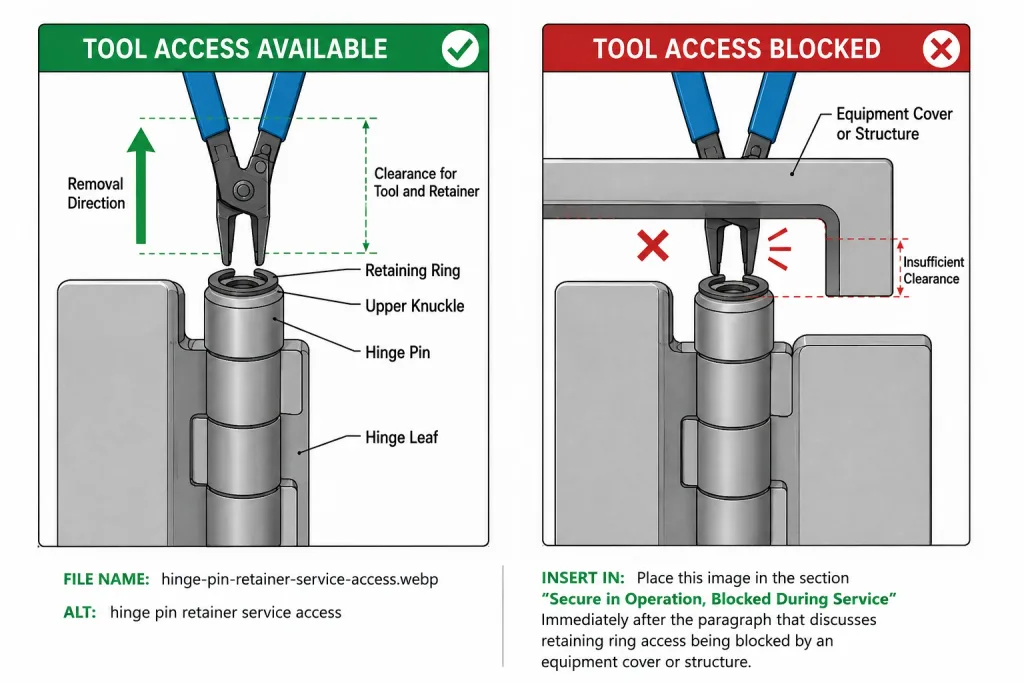
Prototype access can also be misleading. A clip may be easy to reach before a wiring tray, rain hood, guard or internal module is installed and effectively inaccessible in the production assembly.
Environment adds another filter. Exposed grooves and clips can collect chips, paint, dirt or ice. Projecting cotters or safety pins may create snag points. Corrosion and contamination can also make a nominally removable retainer much harder to service. Two applications with similar vibration severity can therefore need different retention methods because their installed environments are different.
Compare Supplier Proposals by Evidence, Not Retention Labels
A quotation that says “retained pin” is not enough to compare two hinges. The proposal becomes useful when the OEM can see what arrests migration, what manufacturing condition controls that feature, and what happens when the pin eventually needs service.
| Proposed Method | What Stops Axial Migration | Production Dependency | Service Consequence | Useful Evidence |
|---|---|---|---|---|
| Staked / swaged / formed end | Formed geometry cannot pass through the release opening | Controlled forming operation after pin assembly | Normally not intended for routine removal | Actual retained-end photo or sample, drawing geometry and confirmation that hinge movement remains free after forming |
| Captive headed pin | Head, shoulder or trapped assembly geometry | Assembly sequence may determine whether the pin can ever be removed | Pin damage may require complete-hinge replacement | Section or drawing showing capture geometry and intended service method |
| Retaining ring | Ring seated in a pin groove | Groove machining, purchased retainer and correct installation | Good serviceability when tool and pin-removal clearance remain available | Ring type, actual groove location, installed access and replacement-part requirement |
| Threaded retention | Threaded hardware creates the end restraint | Thread machining plus the selected locking method | Removable with the specified service tools | Locking method, available tool access and projection in the finished assembly |
| Cross-pin / cotter | Transverse component blocks axial travel | Cross drilling and installation of a secondary component | Visible and removable, but creates another loose service part | Cross-hole location, surrounding clearance and replacement-retainer specification |
| Interference-fit pin | Friction generated by the installed pin-to-bore fit | Pin, bore, surface and assembly control | Removal or wear can change the original fitted condition | Defined fit, relevant dimensions and evidence supporting the expected axial holding behavior |
No method in the table is universally superior. Cost moves between the pin itself, secondary retaining hardware, machining or forming operations, assembly control and future service. An inexpensive part detail can become an expensive equipment decision if it forces destructive removal or complete-hinge replacement later.
Evidence matters when vibration performance is claimed
If a supplier claims that a retained-pin design has been validated for vibration, the useful evidence is the test record rather than the phrase “vibration tested.” The report should identify the tested hinge or sample configuration, retention method, fixture, applied vibration condition, duration or exposure, and what was inspected before and after the test. Any pin-migration acceptance limit should come from the equipment requirement or an agreed project specification.
For projects using broadband random vibration, IEC 60068-2-64:2008+A1:2019 provides a standardized environmental test method for evaluating specimens under specified random vibration conditions. The standard is used together with the relevant product specification to judge acceptability; it does not establish a universal allowable hinge-pin migration or minimum retention force for every application.
Reference: IEC 60068-2-64:2008+A1:2019, Environmental testing — Part 2-64: Tests — Test Fh: Vibration, broadband random and guidance.
Before ordering a sample
The sample request should make the retention architecture comparable without turning the inquiry into a complete production-validation package.
- Pin-removal intent: permanent, occasional overhaul removal or routine service removal.
- Release directions: identify what prevents axial migration at each relevant end.
- Retention mechanism: formed or captive geometry, removable positive stop, interference fit or another clearly defined method.
- Migration consequence: identify what changes first if the pin begins moving—engagement, alignment, neighboring clearance or another functional condition.
- Pin rotation: state whether the pin is expected to rotate or remain fixed to one hinge member.
- Installed access: confirm that the retainer, tool and required pin-removal motion remain accessible in the finished machine.
Once the method has been selected, its production dimensions and acceptance details belong in the controlled hinge drawing. The hinge spec sheet and engineering drawing guide covers the next drawing-review step without duplicating the retention-method decision here.
After the architecture and service conditions are clear, compare suitable industrial hinge models against those requirements rather than choosing from pin style or unit price alone.
Hinge Pin Retention FAQ
What is the best hinge pin retention method for vibration equipment?
There is no universal best method. Permanent formed or captive retention is often appropriate when pin removal is not part of normal service. Retaining rings, threaded retainers and cross-pins are more suitable when controlled removal is required. The choice also depends on migration consequence, axial travel, installed access and the evidence supporting the proposed retention mechanism.
What is positive hinge pin retention?
Positive retention uses geometry that physically blocks further axial travel. Examples include a formed head, retaining ring, cross-pin or captured shoulder. This differs from an interference fit or other design that relies mainly on friction at an interface.
Does a hinge pin need retention in both axial directions?
Both possible migration directions should be reviewed. One direction may already be blocked by a head, shoulder or captured geometry, so a separate retainer is not necessarily required at each end. The important point is that every relevant release path has a defined restraint.
Is an interference-fit hinge pin suitable for vibration equipment?
It can be, but the retention depends on the installed pin-to-bore fit rather than a positive end stop. Pin and bore dimensions, surface condition, coating, knuckle stiffness, assembly method and changes during service should be considered when deciding whether that retention approach is suitable.
Which hinge pin retention methods allow service removal?
Retaining rings, threaded retainers, cross-pins and other positive removable features can allow controlled service removal. The choice depends on removal frequency, available tool clearance, contamination, loose-part control and the required pin-removal path.
Does retaining a hinge pin also prevent the pin from rotating?
Not necessarily. Axial retention and rotational restraint are separate functions. A retaining ring can prevent axial escape while still allowing the pin to rotate. If the pin is intended to remain fixed to one hinge member, that rotational condition needs its own feature or controlled fit.
Compare Retained-Pin Hinge Options for the Actual Installation
Send the hinge location, installed pin direction, service-removal requirement, vibration environment and available end clearance. HSP can use those application details to compare suitable retained-pin industrial hinge options.
Send Your Hinge Requirements