-
+86 13720060320
-
lanna@haitangs.com

Industrial Hinge Mounting Surface Flatness: Leaf Seating, Clamp-Up and Axis Shift
An industrial hinge can rotate freely in the hand, line up with every mounting hole and still become noticeably tighter after the fasteners are fully tightened. When that happens, the fastening operation has changed the geometry of the joint.
Hinge mounting surface flatness matters because the hinge leaf does not locate the pivot axis independently. The leaf sits against a door, frame, bracket or mounting pad. If that surface contains a high spot, local gap, coating ridge or twist, clamp load can bend one member toward the other and move the installed barrel away from its free-state position.
The useful question is not simply whether the screws are tight. Determine what moved as they became tight: the hinge leaf, the mounting face, a shim stack, a formed flange or the complete local structure.
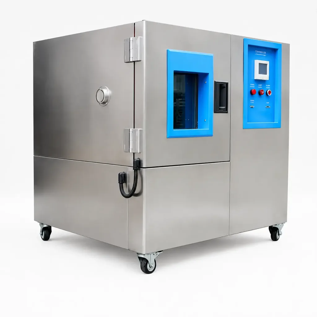
A Flat Hinge Leaf Does Not Guarantee a Flat Installed Joint
Three conditions that look similar on a drawing can behave very differently during assembly.
- Leaf flatness describes the hinge leaf itself before installation.
- Mounting-face flatness describes the local door, frame, bracket or pad receiving the leaf.
- Installed seating describes the contact that remains after fastener clamp load is applied.
A flat hinge leaf cannot make an uneven mounting face disappear without something moving or deforming. If the mounting panel is relatively flexible, the fasteners may pull the panel toward the hinge. If the supporting structure is stiff and the leaf is more compliant, the leaf may bow instead. Where both members are relatively stiff, the joint may retain partial contact and concentrate clamp load around a few local areas.
Each condition can produce a different installed pivot position even though every mounting screw enters its hole normally.
Hole alignment proves that the fasteners can enter the joint. It does not prove that the hinge leaf is fully seated or that the pivot remains on its intended axis after clamp-up.
Read the Contact Before Pulling the Leaf Down
The most useful evidence often exists before final tightening. With the door independently supported and the hinge positioned without using the fasteners to force alignment, look at how the leaf approaches the mounting surface.
A leaf that rocks between opposite corners is different from one that has a continuous gap along one edge. A small isolated high point beside a weld, hole or formed feature points to a different problem from a complete mounting flange that is twisted relative to the hinge axis.
Do not assume that tightening the screws until the visible gap disappears has corrected the condition. The gap may disappear because the joint has been elastically forced into a new shape.
Useful evidence includes the location of visible gaps, rocking direction, contact or transfer marks, coating disturbance, local burrs and whether the barrel visibly changes position as individual fasteners begin to seat.
Check the Mounting Plane Before Final Clamp-Up
Visual inspection can locate an obvious high point, but a repeatable installation needs a reference. Before final tightening, remove loose chips and debris without altering coating, sealant or another finished surface that is intentionally part of the mounting stack.
Where the geometry permits, check the intended seating region against a verified straight reference or inspection surface. A feeler gauge can help locate an edge gap. Light contact-transfer marking can show whether the leaf is carrying across a useful area or only on one corner, one fastener zone or another isolated point.
The pivot can then be referenced to a stable door or frame datum and compared before and after clamp-up. Depending on the size of the assembly and the evidence required, that comparison may use a dial indicator, height reference, controlled fixture or dimensional inspection equipment. The important part is to compare the same functional reference in both states.
First-order geometry: if the pivot centerline is offset from the effective seating plane by a distance h, a small leaf rotation θ produces an approximate lateral pivot shift:
Δ ≈ hθ
for small angles when θ is expressed in radians. This relationship explains the mechanism; it does not establish a universal allowable flatness or axis-shift limit.
The practical consequence is important: an apparently small seating error can become easier to detect at the barrel when the pivot sits farther from the effective mounting plane.

Clamp-Up Can Move the Pivot Without Moving the Hole Pattern
Consider a surface-mounted leaf with several fasteners. If one region of the mounting face stands proud, the first fasteners may seat the leaf against that high point. Tightening fasteners farther away then applies a bending moment to the leaf or pulls the underlying panel toward it.
The fastener centers can remain where the drawing placed them while the barrel rotates slightly with the leaf. The installed hinge axis has moved even though no hole was redrilled and no screw visibly slipped.
This becomes more important when the pivot sits a meaningful distance from the mounting plane. With two or more hinges, the local seating errors also do not have to tilt in the same direction, so individually small changes can create incompatible installed axes.
Clamp load should hold the intended geometry. It should not be the mechanism used to manufacture the geometry after the parts are assembled.
Use the Tightening Stage as Diagnostic Evidence
When hinge movement changes during assembly, note exactly when the change begins. That sequence can locate the interface that deserves attention without immediately removing the hinge or changing the design.
| Observation During Clamp-Up | What It Suggests | Next Area to Inspect |
|---|---|---|
| Leaf rocks before any fastener is tightened | The free leaf and mounting surface do not establish full contact | Local high points, panel twist, formed features, burrs and the leaf itself |
| Movement becomes tight after one fastener or one corner is seated | That clamp point may be rotating or bowing the leaf | Surface condition directly beneath and around that fastener location |
| Leaf looks seated, but barrel position changes as the opposite side is tightened | The joint is bending between clamp points | Mounting-face plane, leaf stiffness, local support and the remaining gap |
| One hinge remains free but the complete hinge set becomes tight | Local seating may have shifted one pivot away from the common axis | Compare the final clamped axis of every hinge station |
| Joint is acceptable before finishing but changes when production-finished parts are assembled | The finished mounting stack may no longer reproduce the original seating plane | Coating ridges, masking boundaries, trapped debris and final surface condition |
| Fasteners repeatedly lose clamp after the panel is pulled into position | The joint may be settling, slipping or relying on local panel deformation instead of stable seating | Contact marks, coating compression, washer support, local yielding and mounting-zone stiffness |
This comparison does not set a universal tightening sequence or fastener torque. Those values depend on the actual fastener, thread, finish, locking method, parent material and joint design. The sequence is useful here because it reveals when the installed geometry changes.
High Spots Often Come From the Mounting Stack, Not the Hinge
An apparently simple mounting face can contain several local features capable of changing leaf seating.
Burrs and Raised Hole Edges
A hole can be dimensionally acceptable while material around its edge sits above the intended mounting plane. When the hinge leaf bridges that raised area, final tightening may create a local fulcrum instead of uniform contact.
Welds and Distortion Near the Mounting Pad
A reinforcement, weld nut, bracket or nearby seam can move the mounting pad even when the hinge itself is bolted on later. Evaluate the joint after the fabrication operations that establish its final shape rather than judging only an earlier flat blank or unfinished subassembly.
Formed Returns and Bend Transitions
A hinge leaf that extends too close to a bend radius or formed step may not be sitting on the nominal flat plane suggested by a simplified front view. A narrow return can also rotate under clamp load when the hinge region has insufficient support.
Coating, Sealant and Surface Build-Up
Powder coating, paint, sealant or another finishing process can change the finished seating surface. A ridge at a masking boundary or uneven build-up around a hole can behave like a thin wedge beneath the leaf.
Do not remove a coating or modify a finished surface merely because a hinge feels tight. First determine whether that surface belongs in the released mounting stack and whether changing it would affect corrosion protection, sealing, electrical bonding or another project requirement.
A Shim Should Establish a Plane, Not Chase Individual Gaps
Shims can be useful when the assembly intentionally includes adjustment, but an uncontrolled stack placed wherever a visible gap appears can create another seating problem.
A shim changes the mounting plane. Its area, position and thickness determine whether the hinge leaf is properly supported or simply pivoted around another local point. A small washer-like spacer under one corner can raise that corner while leaving much of the leaf unsupported.
Where production requires shimming, the final arrangement should be repeatable. The shim should support the intended region, remain captured after tightening and be identifiable during service or replacement. If every unit needs a different improvised stack to make the hinge move freely, the mounting geometry deserves correction.
For thin doors and frame sections where the mounting surface itself cannot remain stable under fastener load, the thin sheet-metal hinge mounting guide covers backing plates, threaded inserts, reinforced returns and other structural attachment methods.
Multiple Hinges Amplify Local Seating Errors
A single hinge does not have to share its pivot axis with a second separate hinge station, so some mounting errors remain local to that joint. A multi-hinge door is less forgiving because every additional pivot adds another geometric constraint to the same moving panel.
If the upper leaf tilts one way during clamp-up while the lower hinge remains on its intended plane, both hinges may still accept every fastener. The door may also look correctly positioned while stationary. During rotation, however, the pivots attempt to follow different centerlines and side load develops within the hinge set.
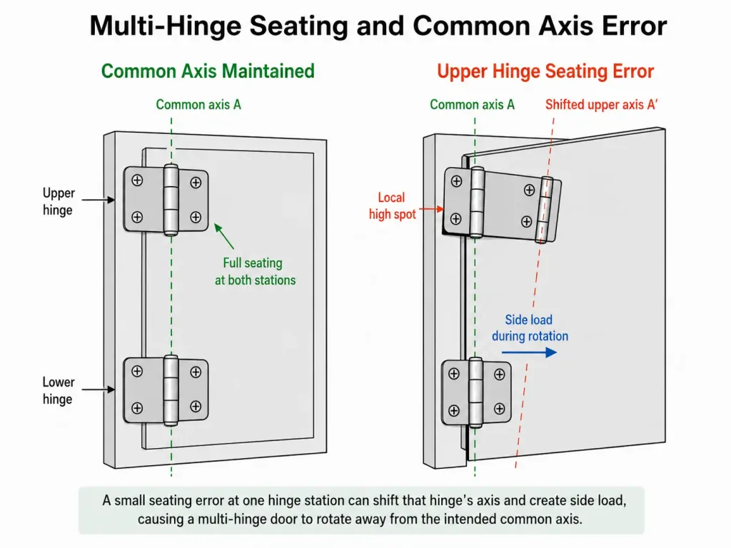
This is why checking each hinge loose on the bench cannot prove the installed multi-hinge assembly. The relevant condition is the final clamped hinge set on the real door and frame.
When diagnosing an existing assembly, support the door independently before changing any loaded hinge joint. If permitted by the equipment service procedure, observe whether resistance changes as the clamp state at one hinge station is released and restored. Do not use the hinge pin to force incompatible barrels into line, and do not leave the remaining hinges carrying an unsupported door.
Tightening Order Can Reveal a Problem, but It Should Not Hide One
Progressive tightening is useful because it shows whether one fastener or one side of the leaf changes the motion. It also avoids immediately applying full clamp load to a joint whose seating condition has not been understood.
Suppose the hinge is free with all fasteners engaged lightly, remains free when two adjacent fasteners are seated, then becomes tight when the opposite corner is pulled down. Repeating that sequence provides better evidence than simply loosening every screw until the door feels acceptable.
The final assembly still needs its specified clamp condition. Leaving one fastener loose, permanently reducing clamp without engineering approval or relying on fastener flexibility to preserve motion trades an alignment symptom for a joint-retention problem.
If the hinge only works when the mounting joint is intentionally left loose, the seating or axis problem has not been solved.
Put the Seating Condition on the Drawing or Work Instruction
A hole pattern alone cannot define the final hinge position when leaf seating affects the pivot. Released manufacturing information should control the features that actually establish the mounting plane.
- Identify the functional mounting face or pad. The drawing and process should agree on which surface establishes leaf seating.
- Protect the required seating region. Bend transitions, weld build-up, burrs and other raised features should not occupy an area that depends on full contact.
- Define the finished surface condition. State the intended condition when coating, plating, sealant or another process remains between the hinge and mounting face.
- Control intentional spacers and shims. A designed spacer, machined pad or shim should be part of the mounting stack rather than an undocumented assembly correction.
- Define the inspection state. When the functional axis depends on clamp-up, specify whether it is checked on the loose hinge, in a fixture or on the representative clamped assembly.
When the mounting face, shim stack or clamped-axis inspection needs to appear on a supplier drawing, the hinge spec sheet and engineering drawing guide explains how to document those fields, revisions and inspection evidence.
Validate the Final Clamped Joint, Not Just the Loose Parts
The mounting interface should be evaluated in the same state that controls the working hinge. A loose leaf, an unclamped panel and an unfinished mounting pad can all give a false impression of the final result.
For a representative assembly, preserve a useful baseline before changing the joint. Confirm that the candidate hinge moves as expected before mounting, record any rocking or gap at the mounting face, and then follow the approved fastening process while observing the barrel position and movement.
After final clamp-up, check the complete hinge set through the required movement with the door in its intended supported condition. Look again at seating edges, fasteners and the mounting structure. New witness marks, local gaps, leaf bowing or movement in the supporting panel show that the mounting interface is still changing under assembly load.
If the seating remains stable, the hinge axes remain compatible and the door moves correctly in the final assembly state, the mounting condition is doing its job. If not, determine whether the correction belongs in the hinge geometry, mounting surface, structural support or fastening process before changing the hinge model.
Once the mounting architecture and seating plane are defined, compare available industrial hinge models against the actual mounting envelope, door function and project requirements.
Hinge Mounting Surface Flatness FAQ
How can I tell whether an industrial hinge leaf is fully seated?
Check the leaf before final tightening for rocking, edge gaps and isolated contact points. Then observe whether those conditions disappear because the parts seat naturally or because clamp load bends the leaf or mounting surface. The final joint should reproduce the intended mounting plane without relying on uncontrolled deformation.
How can mounting surface flatness be checked before tightening a hinge?
Where the hinge geometry allows it, inspect the seating area against a verified reference surface and use edge-gap checks, a feeler gauge or light contact-transfer marking to locate incomplete contact. If pivot position is critical, compare the same barrel or axis reference before and after clamp-up.
Can shims be used behind an industrial hinge leaf?
Yes, when shimming is an intentional part of the mounting design. The shim area, position, thickness and retention should establish a repeatable support plane. Small improvised spacers under individual fasteners can tilt the leaf and move the pivot instead of correcting the mounting surface.
Should hinge alignment be checked before or after final tightening?
Both states provide useful information, but the final clamped state controls the installed result. If the axes are compatible before tightening and move out of alignment only after clamp-up, inspect leaf seating, the mounting plane and local structural deformation before changing the hinge.
Can powder coating or paint under a hinge leaf affect seating?
It can if the finished surface contains uneven build-up, a masking ridge, trapped debris or another local thickness change. Do not assume the coating should be removed. First confirm whether it belongs in the released mounting stack and whether removal would affect corrosion protection, sealing or another requirement.
When should the mounting surface be corrected instead of replacing the hinge?
If the hinge moves correctly in its free state or on a suitable reference surface but changes only when attached to the production door or frame, investigate the mounting interface first. Replace the hinge when inspection identifies an actual hinge defect, permanent deformation, damaged pivot or another fault that remains independent of the mounting surface.
Send the Mounting Interface, Not Just the Hinge Photo
If a hinge changes position or movement during final tightening, send the hinge model or drawing, the door and frame section around the hinge, mounting-face construction, finish condition, fastener layout and clear photos of the leaf before and after clamp-up. HSP can compare available hinge geometry and product information with the mounting condition and identify which interface details still need to be resolved for the project.
Send the Mounting Details