-
+86 13720060320
-
lanna@haitangs.com

Industrial Hinge Axis Alignment: Why Multi-Hinge Doors Bind After Assembly
The bolts can fit. The hinge axes can still be wrong. A multi-hinge industrial door may swing reasonably well while the fasteners are loose, then become noticeably harder to move after final tightening. Replacing the hinges does not necessarily change the behavior. Enlarging the holes may make assembly easier without making the result repeatable.
The door, frame, brackets and hinge leaves can force two nominal rotation axes into one strained assembly. Clearance in the mounting joints allows the hardware to go together, while final tightening transfers the remaining geometry error into the surrounding structure and pivot interfaces.
Industrial hinge axis alignment is therefore not just a visual check that the upper and lower hinges appear vertical. The practical question is whether all installed rotating interfaces can follow one common axis without requiring the door, frame, mounting surfaces or hinge pins to bend, twist, slide or remain preloaded.
Diagnostic rule: If the door becomes stiffer when all hinge fasteners are fully tightened, investigate stored assembly strain before treating hinge friction as the primary cause.
Binding After Final Tightening
A hinge that is internally too tight can make a door difficult to move. So can a cable, gasket, door edge or opening stop. Axis misalignment has a different signature because the resistance is created by the relationship between two or more installed pivots.
One hinge may rotate freely by itself. The second hinge may also rotate freely when tested separately. Bolt both to a sufficiently rigid door and frame, however, and both pivots now have to describe the same rotation.
When their centerlines do not agree, the error has to be absorbed somewhere. Clearance holes allow a leaf to shift. A slotted bracket can move. Thin sheet can dish. A long door can twist. A mounting flange can spring. Pin and bushing interfaces can accept additional side load.
Those freedoms can hide the geometry error during assembly. Final tightening removes some of that freedom by clamping the hinge leaves to the mounting surfaces. The remaining mismatch becomes elastic strain and reaction force through the door system.
The resulting resistance may be small enough that the door still operates, yet high enough to change opening effort, load sharing and long-term wear.
One Door, One Practical Rotation Axis
Two single-axis hinges on a rigid door do not create two independent rotations. They behave as one mechanism only when their axes are coincident closely enough for the actual bearing clearance, mounting variation and structural compliance of the assembly.
Perfect mathematical coaxiality is not a useful universal production requirement. Real hinges contain clearance and dimensional variation. Door and frame structures are not infinitely rigid. What matters is whether the remaining error allows the completed door to meet its required operating force, position, movement and service life without harmful side loading.
When the upper hinge tries to rotate around one line and the lower hinge around another, the door becomes an over-constrained mechanism. The disagreement is absorbed through local deflection and movement at the interfaces rather than disappearing.
Assembly proves that the fasteners can reach their holes. It does not prove that the rotating axes agree.
Part Geometry Is Not Pair Alignment
A controlled hinge drawing can accurately define leaf width, hole diameter, mounting-hole spacing, pin diameter, material and other part-level geometry. Those dimensions control the hinge itself. They do not automatically prove that two completed hinge locations on the door and frame will form one common installed axis.
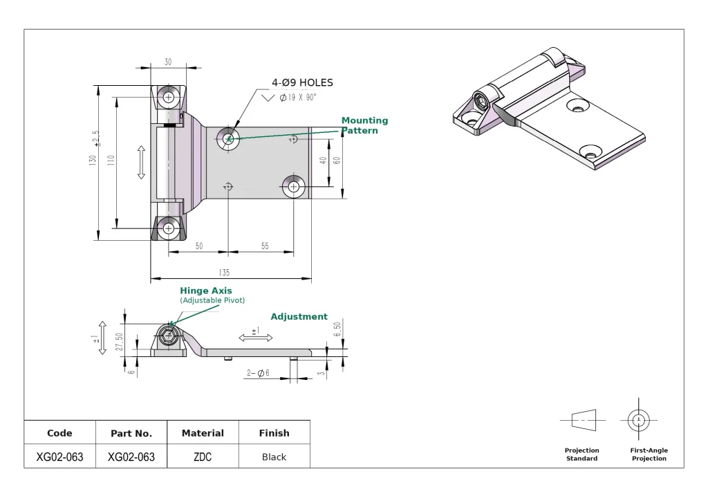
The upper hinge may be manufactured correctly. The lower hinge may also be within tolerance. Each mounting pattern can pass dimensional inspection, while the combined door-side and frame-side tolerance stack still shifts one installed centerline relative to the other.
This is why replacing one in-tolerance hinge with another can reproduce the same binding. The source may be the location or orientation of the mounting interfaces rather than the hinge component.
For datum selection, mounting-pattern position and hinge-axis tolerances on the drawing, see our guide to industrial hinge tolerances before RFQ.
Three Forms of Axis Error
Misalignment becomes easier to diagnose when the geometry is separated into three different conditions.
| Axis Error | What Changed | Typical Assembly Evidence | Where to Look Next |
|---|---|---|---|
| Parallel offset | The upper and lower axes remain approximately parallel but are laterally displaced. | The door can be pulled into place; a hinge leaf or bracket may shift when mounting constraint is released. | Hole-pattern position, shims, slots, bracket location and frame datums. |
| Angular misalignment | The two axes point in different directions. | Resistance may remain through the swing; pin or bushing contact can concentrate toward one end. | Mounting-face angle, bracket roll, formed flange, weld distortion and leaf seating. |
| Moving support | The axes agree in one condition but the supporting structure moves after tightening or loading. | Door behavior changes with fastener preload, door mass, temperature or frame condition. | Thin sheet, flexible brackets, reinforcement, body twist, weld movement and joint slip. |
The third condition can escape a simple unloaded alignment check. A fixture may show the two centers on one line before the full production door is installed, while the actual door weight or fastener preload moves one mounting edge enough to change the operating axis.
A straight reference line is useful evidence, but it should be checked in the condition that actually creates the problem.
The Latch Can Hide Misalignment
Industrial latches can pull the free edge of a door toward a keeper or gasket land. That is useful for closure and sealing, but it can also hide hinge-side geometry that would otherwise be visible.
An out-of-axis hinge arrangement may leave the free edge slightly high, low or twisted. Once the latch engages, it can draw the panel back into the opening. The final closed gap may appear acceptable even though the hinge line, mounting brackets, door panel and latch are all carrying a correction load.
Compressed gaskets can create the same diagnostic problem. Gasket force biases the door near its closed position and then reduces as the panel opens. Checking only the last few degrees of movement can therefore make gasket drag and hinge-axis binding difficult to separate.
Inspect the free-state geometry with the door supported as required by the design, the latch disengaged and the gasket no longer applying meaningful pull-in force. Compare the upper and lower gaps and the position of the free edge before the latch draws the door home.
The latch should secure the intended closed position. It should not be the alignment fixture for the hinge system.
Separate Axis Error From Other Binding
Door binding does not automatically mean the hinge axes are misaligned. The operating pattern helps separate axis error from internal hinge friction, interference and other movement problems before hardware is changed.
| Observed Behavior | More Consistent With | Competing Explanation | Useful Next Check |
|---|---|---|---|
| Door moves freely with hinge fasteners loose, then stiffens as they are tightened. | Stored mounting strain or axis misalignment. | Leaf distortion caused by excessive fastener preload. | Support the door and perform a controlled release check. |
| One loose hinge is already stiff before installation. | Internal hinge friction, pin/bore fit or pivot damage. | Contamination or finish buildup. | Evaluate the hinge away from the door structure. |
| Resistance appears sharply at one opening angle. | Local interference, cable pull or stop contact. | Mechanism geometry. | Inspect the moving envelope at the angle where force increases. |
| Resistance remains elevated through a broad portion of the swing after tightening. | Axis error or mounting distortion. | Uniformly high hinge friction. | Compare the installed condition with one mounting interface carefully released. |
| Door aligns only when the latch is pulled tight. | Hinge-line, door or frame position error. | Intentional gasket pull-in. | Inspect free-state gaps before latch engagement. |
| Visible lateral looseness with little opening resistance. | Pin clearance, bushing wear or side play. | Loose mounting joint. | Inspect pivot clearance and mounting movement separately. |
| Door moves along the pin direction. | End play or axial-stack movement. | Intentional lift-off clearance. | Measure axial movement rather than treating it as axis misalignment. |
| The problem begins only after final welding. | Post-weld centerline or mounting-face distortion. | Weld spatter or heat damage at the pivot. | Measure the finished cooled structure. |
If the unresolved issue is the running fit between the pin and bore rather than the relationship between multiple hinge locations, use the hinge pin clearance guide. Both faults can raise opening force, but they require different corrections.
The Release Test Exposes Stored Assembly Strain
A useful check for suspected multi-hinge misalignment is to observe how the assembly responds when one mounting constraint is gradually reduced. The goal is not simply to loosen bolts. It is to see whether the structure has been holding the hinge away from its relaxed position.
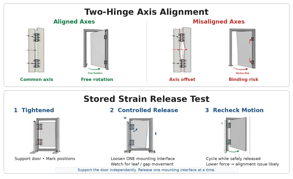
Do not perform this check with an unsupported heavy door. Support the door independently so releasing one interface cannot let the panel drop, rotate unexpectedly or overload another hinge. Gas springs, closers and other assistance should be considered because their forces can mask the result.
- Record the fully tightened condition. Note opening resistance through the swing, free-state door gaps, latch position and visible leaf or bracket distortion.
- Add witness marks. Mark the relationship between the hinge leaf and mounting surface so a small shift becomes visible.
- Support the door independently. Hold the intended door position without using the hinge pair as the support fixture.
- Release one interface gradually. Reduce clamp constraint only enough to allow the leaf to relax while keeping the hinge safely captured.
- Watch the mounting interface. Sliding, rotation, separation from the mounting face or a door-gap change indicates that the tightened assembly was carrying stored strain.
- Cycle the door again. A meaningful reduction in operating resistance after one interface is released points back to the mounting relationship.
- Repeat in a controlled sequence. Isolate upper versus lower hinge and door-side versus frame-side leaf instead of loosening several locations at once.
A leaf that does not visibly move can still be part of an alignment problem because the surrounding frame or door may be carrying the deformation. Use the release result together with the change in operating force, door gap, bracket position and witness marks.
Measure the Installed Hinge Line
Once the release test suggests an alignment problem, convert the observation into geometry. The upper and lower hinge locations should be referenced from the same door or frame datum system rather than measured independently from nearby sheet edges.
For a simple two-hinge arrangement, record the installed pivot-center position at the upper hinge and lower hinge relative to one stable reference plane or edge. The useful comparison is not whether each location matches its own nominal dimension. It is whether the two measured locations describe the same intended hinge line.
Position alone is not enough. A hinge center may be in the correct lateral location while its local pin or bore axis is tilted because a bracket is rolled, a mounting face is not square, a shim is uneven or welding has rotated the hinge body. Check both center position and local axis direction when the structure permits it.
A simple geometric screening relationship can help quantify angular disagreement. If two hinge reference locations are separated by a distance L and their relative lateral displacement changes by Δ over that span, the small-angle relationship is approximately:
α ≈ Δ / L
where α is in radians when Δ and L use the same unit. This relationship is a geometric screening tool, not a universal hinge acceptance tolerance. The allowable error still depends on bearing clearance, hinge spacing, door stiffness, mounting structure and the operating requirement of the complete assembly.
Measurement should also reproduce the state in which the problem occurs. A hinge line that appears acceptable with the door removed may move after the production door is installed. A welded frame may change again after cooling. A flexible cabinet can move when fully tightened. Record the condition together with the measurement rather than treating an unloaded centerline as final proof.
Where the Axis Moves
The installed hinge line is created by the complete stack between the pivot and the load-carrying structure. Mounting holes are only one possible source of error.
Clearance Holes and Slots
Clearance holes permit assembly variation. Slots permit more variation in a selected direction. Neither feature defines where the hinge finally stops after the joint is tightened.
If the upper hinge sits at one end of its adjustment and the lower hinge at the opposite end, both sets of fasteners may be correctly installed while the pivot lines no longer agree. Washer and slot witness marks can reveal movement that occurred after initial alignment.
Flexible Mounting Edges
Thin sheet and narrow formed flanges can move under fastener preload and door reaction. A mounting surface may begin in the correct nominal position and leave that position when the joint is clamped or loaded.
For backing plates, inserts, reinforcement and thin-panel joint stability, use the thin-sheet hinge mounting guide.
Weld Distortion
A weld-on hinge can be aligned correctly during tack-up and move during final welding. Heat input, weld sequence, bracket stiffness and the surrounding section all influence the final centerline.
For alignment diagnosis, the important state is the cooled finished structure that controls door operation—not only the hinge position before the final weld.
Shims, Coating and Bracket Seating
A shim changes position and can also change leaf angle when support is local or uneven. Coating buildup, weld beads, burrs and formed-radius interference can prevent a hinge leaf from seating flat. Tightening then bends the leaf or bracket against the mounting surface.
Axis error can therefore exist even when the mounting holes themselves are in the correct position.
The Third Hinge Can Make It Worse
Adding another hinge is often treated as a straightforward way to improve a heavy or tall door. Structurally, the additional support may be necessary. Kinematically, it introduces another pivot that must remain compatible with the same rotation axis.
If two hinges already define a workable axis and a third is installed slightly off that line, the additional hinge can force the door and frame to deform until all three pivots can move together. Opening effort can increase even though the nominal structural capacity of the hinge set has also increased.
This separates load capacity from constraint compatibility. Additional hinge capacity does not correct a geometric conflict.
Tall or heavy doors may still require three or more support points. Hinge count and spacing belong to the structural design; the heavy enclosure door hinge guide covers that calculation. Every required hinge still needs to participate in the common-axis strategy.
Correct the Source of Constraint
Increasing every mounting-hole diameter is rarely the best first correction. More clearance can make assembly easier while reducing repeatable hinge position.
- Displaced hole pattern: correct the pattern or establish controlled adjustment from stable mounting references.
- Angled mounting face: correct the bracket or seating surface. Avoid local shimming that twists the hinge leaf.
- Flexible panel: reinforce the mounting zone or change the joint so clamp load does not reshape the hinge interface.
- Post-weld movement: correct fixturing, tack sequence or surrounding structure rather than pulling the door onto a distorted hinge line.
- Drifting slot position: define the required adjustment direction and use a joint that locks the final setting against service movement.
- Moving door or frame structure: include support stiffness in the correction. A precision hinge cannot keep two flexible mounting points stationary.
- Individual hinge remains stiff when removed: investigate the pivot, bushing, finish, contamination or internal damage instead of continuing to correct alignment.
A successful correction leaves the door relaxed in its intended geometry. If tightening the fasteners still has to pull the structure into alignment, the mechanism remains dependent on assembly strain.
Verification After Rework
Verify the corrected door under the same conditions that exposed the original problem.
Begin with the free-state door before the latch pulls the panel against the frame. Upper and lower gaps should remain stable, and the door should not visibly move to a new position when temporary support is removed under the intended mounting condition.
Cycle the complete normal opening range with every hinge fastener fully tightened. Watch for a broad increase in resistance, a local force spike, leaf movement, fastener slip, bracket flex or contact at an adjacent component. A local spike may indicate interference; broadly elevated resistance is more consistent with continuing constraint.
Engage the latch and gasket only after the free-state condition is understood. Latch effort and gasket compression should follow the intended closed geometry rather than supply the force required to reposition a misaligned door.
If the project uses an opening-force or operating-torque acceptance value, keep the handle position, direction, hinge angle and assembly condition consistent between readings. A before-and-after comparison is useful only when the measurement basis is unchanged.
Inspect witness marks again after the required cycling or representative service condition. Movement at a leaf, slot, shim or bracket can show that the corrected axis was not stable even when the door felt acceptable immediately after adjustment.
When Rework Keeps Coming Back
If every production batch requires manual pushing, undocumented shims, enlarged holes or hinge-by-hinge adjustment before the door moves freely, the problem is no longer a one-time installation correction. The production definition or fixture may not be controlling the relationship that establishes the hinge line.
Record which mounting surfaces actually locate the successful assembly, where adjustment is required, which feature establishes each pivot center and in what finished condition alignment must be checked. Those findings should then be transferred into the controlled drawing or production fixture instead of remaining operator knowledge.
The detailed drawing work belongs in the industrial hinge tolerance guide. For this diagnosis, the important result is repeatability: the door should no longer depend on hidden assembly strain to operate.
Multiple hinges need enough geometric control to share one practical rotation axis in the installed condition. Tighter tolerances are useful only when they solve a measured assembly requirement.
Share the Installed Geometry and Binding Evidence
For an HSP hinge review, send the door and frame section, upper and lower hinge locations, mounting method, hinge quantity, free-state door gaps, photos of the installed hinge leaves, and a short description of when resistance appears—before tightening, after tightening, near the closed position, or through the full swing. Those details are more useful for diagnosing an axis problem than a hinge photograph alone. Send the door geometry and binding details.
Industrial Hinge Axis Alignment FAQ
Can industrial hinges be misaligned even if all the bolts fit?
Yes. Clearance holes, slots and structural flexibility can let fasteners enter even when the installed hinge centerlines do not share one practical rotation axis. Final tightening can then transfer the remaining geometry error into the door, frame, brackets or hinge pivots as assembly strain.
Why does a multi-hinge door bind only after the hinge bolts are tightened?
Loose mounting joints may provide enough freedom for each hinge to follow its preferred position. Tightening clamps the leaves to the mounting surfaces and removes that freedom. If the hinge axes or mounting faces disagree, the remaining error is carried as elastic strain and side load.
How can I tell hinge-axis misalignment from tight hinge pin clearance?
An internal pivot or pin-clearance problem normally remains with the individual hinge when it is evaluated away from the door structure. Axis misalignment is created by the relationship between multiple installed hinge locations and can change when one mounting constraint is carefully released.
Does adding a third hinge reduce door binding?
Not automatically. A third hinge can improve structural support when the door design requires it, but its axis must remain compatible with the other hinges. An off-axis intermediate hinge can add constraint and increase operating force even while the nominal load capacity of the hinge set increases.
Can weld-on hinges become misaligned after welding?
Yes. A hinge can be positioned correctly during tack-up and move during final welding as heat distorts the bracket, leaf or surrounding structure. Alignment should be evaluated in the finished cooled condition that controls door operation.
Do industrial hinge axes need to be perfectly coaxial?
No universal zero-error requirement applies to every industrial door. Real hinges have running clearance, manufacturing variation and structural compliance. The required alignment is the condition that lets the complete door meet its operating-force, movement, wear and positioning requirements without harmful stored strain or side loading.
Can the door latch hide hinge misalignment?
Yes. A latch can pull a shifted or twisted door toward the keeper and gasket, making the closed gaps look acceptable while the hinge system remains preloaded. Inspect the free-state door position with the latch disengaged before using the closed appearance as evidence of alignment.
How can hinge-axis misalignment be measured?
Measure the upper and lower pivot locations from the same stable door or frame datum, then compare whether those points and their local axis directions describe one intended hinge line. If the lateral disagreement changes by Δ over a hinge spacing L, α ≈ Δ/L can be used as a small-angle geometric screening relationship. The allowable limit remains project-specific.