-
+86 13720060320
-
lanna@haitangs.com

How to Replace a Discontinued Torque Hinge
Your supplier has marked the hinge end-of-life. Production still needs to continue, field units still need spare parts, and the old drawing may be incomplete. The tempting response is to search for the same hole pattern and the same nominal torque. That is also how many replacement projects go wrong.
To replace a discontinued torque hinge reliably, rebuild the controlled function of the old part: where its axis sits, how it resists movement in each direction, which angles it must hold, how it shares load with the second hinge, and what environmental and lifecycle conditions it must survive. The successor may come from a current torque hinge range, a modified existing platform, or a new custom design. The route is secondary. Functional equivalence comes first.
Replacement rule: Do not approve an equivalent because it looks the same or carries the same N·m label. Approve it only after the geometry, torque behavior, direction, installed load path, and lifecycle evidence have been compared under defined conditions.
How to Replace a Discontinued Torque Hinge Without Guessing
A discontinued hinge creates two different problems. The obvious one is supply: the part can no longer be ordered. The less visible one is definition: the old part may never have been controlled well enough for another manufacturer to reproduce or replace it.
An old bill of materials may contain only a supplier part number. A catalog page may show one torque value but not say whether it is opening, closing, breakaway, running, or holding torque. The installation drawing may locate the screw holes while leaving the hinge-axis position implicit. A used sample may still fit perfectly but may have lost torque after years of service. Each source contains useful information. None should be treated as the complete specification by itself.
The replacement task is therefore not “find a similar hinge.” It is to create a controlled replacement baseline that answers three questions:
- Will it fit? The hinge axis, mounting pattern, envelope, fasteners, handedness, and opening path must work in the existing equipment.
- Will it behave correctly? The panel must move with acceptable effort and remain at every required position in both directions of travel.
- Will it remain acceptable? Materials, temperature behavior, contamination resistance, load capacity, cycle life, and torque retention must suit the actual duty.
The finished output should be more than a new part number. It should include an approved replacement drawing, a written list of deviations from the legacy part, defined torque and functional acceptance limits, and a sample validated in the final assembly.
Freeze the Legacy Configuration
Before measuring the old hinge, identify exactly which equipment configuration is being replaced. A hinge used on three product revisions may look identical while carrying a different torque, bracket offset, stop angle, finish, or handed orientation. Mixing those versions produces a replacement that is “close” to all of them and controlled for none of them.
Start with the assembly, not the loose part. Record:
- Equipment model, customer part number, and assembly revision
- Legacy supplier name, supplier part number, customer part number, and drawing revision
- Quantity of hinges per panel and the position of each hinge
- Door, lid, display, or cover mass in its complete production configuration
- Hinge orientation, left/right handing, and which leaf or shaft end mounts to each side
- Required opening range, service positions, mechanical stops, and closed position
- Fastener type, mounting substrate, reinforcement, and tool-access restrictions
- Cables, gaskets, hoses, latches, covers, or nearby structures that influence motion
- Operating environment, expected cycle duty, and known field failures
Also state the commercial scope. A service replacement normally needs a drop-in interface because field technicians cannot drill new holes or change brackets across installed equipment. A new-production successor may allow a revised hole pattern, fastener, or bracket if the equipment drawing and assembly process can be changed. A project that serves both populations may need two solutions: a true drop-in service part and a lower-risk production redesign.
This distinction affects cost more than many small dimensional differences. Requiring a perfect copy can force custom tooling. Allowing a controlled equipment-side change may open several standard platforms. Neither route is automatically better; the replacement purpose decides.
Legacy Evidence: What Can Still Be Trusted?
Build the baseline from several evidence sources. Give each one the job it can actually perform.
| Evidence | What It Can Establish | Main Risk | Replacement Action |
|---|---|---|---|
| Released legacy drawing | Controlled dimensions, hole pattern, material notes, orientation, revision | Functional values or test conditions may be missing or obsolete | Use as the geometry baseline and identify every uncontrolled field |
| Original data sheet or test report | Nominal torque, tolerance, cycle or environmental claims, test conditions | May describe a family rather than the exact ordered configuration | Match the part number and revision to the physical sample |
| Unused retained sample | Original fit, surface, motion, torque behavior, and assembly details | Storage age or unknown production variation may affect the result | Measure it under controlled conditions and preserve it as a reference |
| Used field sample | Wear locations, corrosion, looseness, real installation marks, failure evidence | Current torque may represent degradation, not the original requirement | Use for failure analysis and geometry confirmation, not as the only torque target |
| Complete working assembly | Actual hand force, holding angles, cable and gasket effects, interference, paired behavior | A worn assembly may already be outside its intended condition | Document what is acceptable, what has changed, and what the replacement must correct |
| Purchase records and packaging | Supplier identity, suffixes, finish codes, order history, revision clues | Commercial names may not define the engineering configuration | Use them to trace the correct legacy model, not to approve equivalence |
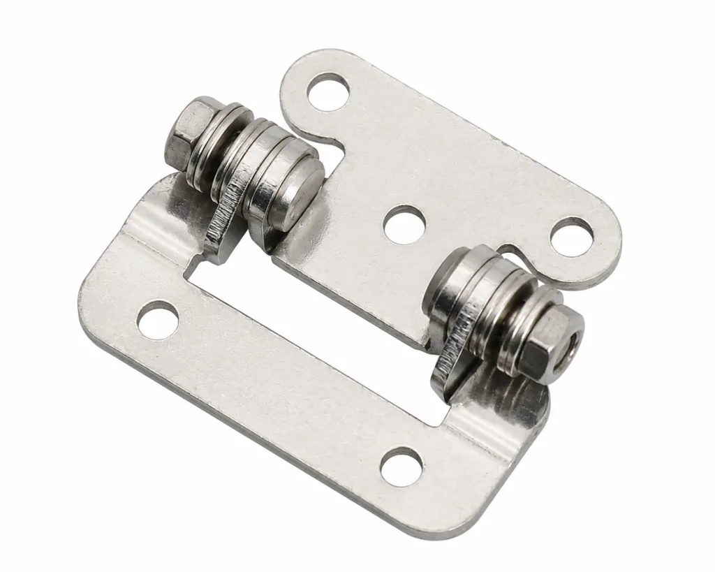
The strongest baseline normally combines a released drawing, an unused sample when available, one or more used samples with known service history, and the complete assembly. There is no universal sample quantity for every replacement program. Use enough units to reveal the variation that matters for the equipment risk, production volume, and consequence of a wrong replacement.
Function Before Form
Two hinges can share the same outline and solve different motion problems. Before searching catalogs, write down what the legacy mechanism actually does.
Start with the required position-control behavior:
- Does the panel hold at any angle, only within a free-stop range, or only at fixed detent positions?
- Is resistance required in both directions, or should one direction move with little resistance?
- Are opening and closing torque intended to be equal, or deliberately asymmetric?
- Is a high initial breakaway acceptable, or must movement start smoothly after a long dwell?
- Does the hinge include a mechanical stop, a released zone near closing, or another angle-dependent feature?
- Must the panel remain stable under vibration, cable pull, gasket force, user contact, or an inclined installation?
- What hand-force range is acceptable at the real handle or contact point?
Then define the load the hinge system must control. Include the complete moving mass, center-of-gravity location, hinge quantity, panel orientation, mounted accessories, and any force that changes through the opening arc. Do not infer the required torque from the old hinge alone if the equipment has changed since it was selected. A heavier display, new cable bundle, thicker gasket, or added cover can make the old part number a poor design target even before it is discontinued.
The replacement does not need to copy the hidden internal mechanism if another mechanism produces the required motion within the approved package and life limits. It does need to reproduce the equipment behavior that users, safety functions, latches, cables, and mounting structures depend on.
Mounting Geometry at the Hinge Axis
The leaf outline is easy to photograph. The hinge axis is what controls the machine. A small shift in axis location can change the panel sweep, closed gap, cable bend, gasket compression, handle position, and load moment even when every mounting hole lines up.
Review the old and proposed drawings from common equipment datums. The site guide on reading a hinge spec sheet and engineering drawing covers document control and tolerance interpretation in detail; the replacement review should concentrate on the interface fields below.
| Interface Field | Why It Controls Replacement Fit | Evidence to Provide |
|---|---|---|
| Axis location | Controls panel path, moment arm, gaps, seals, and nearby interference | Dimension from released door and frame datums to the rotation centerline |
| Hole pattern and pattern origin | Determines drop-in interchangeability and multi-hinge alignment | Hole size, spacing, positional tolerance, countersink or counterbore details |
| Leaf, bracket, and shaft geometry | Sets mounting offset, stiffness, engagement, and load path | Section views, thickness, offsets, shaft length, and mounting-side identification |
| Installed envelope | Prevents collision with housings, covers, fasteners, cables, and tools | Closed, intermediate, and fully open keep-out zones |
| Handing and direction marks | Prevents reversed installation and wrong high-torque direction | Viewing reference, door leaf, frame leaf, clockwise/counterclockwise or opening/closing arrows |
| Fastener and substrate | Controls clamp load, thread engagement, local distortion, and service access | Fastener size, head style, length, thread, washers, panel thickness, and reinforcement |
| Opening limit and closed condition | Protects cables and stops the panel at the required service or storage position | Angle reference, tolerance, stop contact, and whether the stop is in the hinge or equipment |
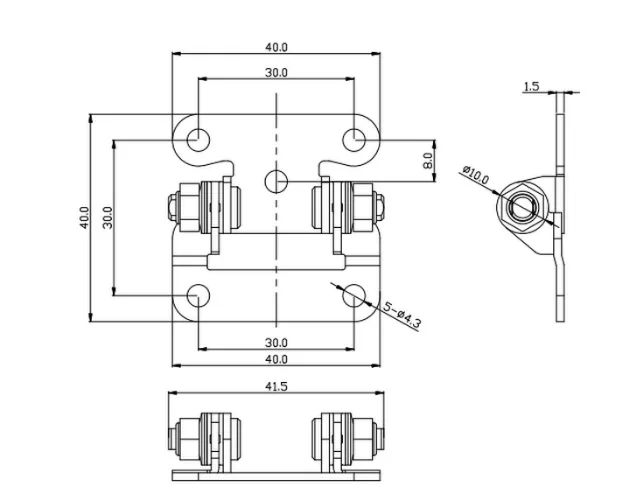
Do not scale a PDF or photograph to create production dimensions. Measure the physical part for investigation, but release the replacement against stated dimensions and tolerances. If two or more hinges share one panel, their practical axes must remain coaxial across the equipment tolerance range. A replacement that requires the mounting screws to pull misaligned leaves into position is not a drop-in equivalent.
Torque Behavior of the Original Hinge
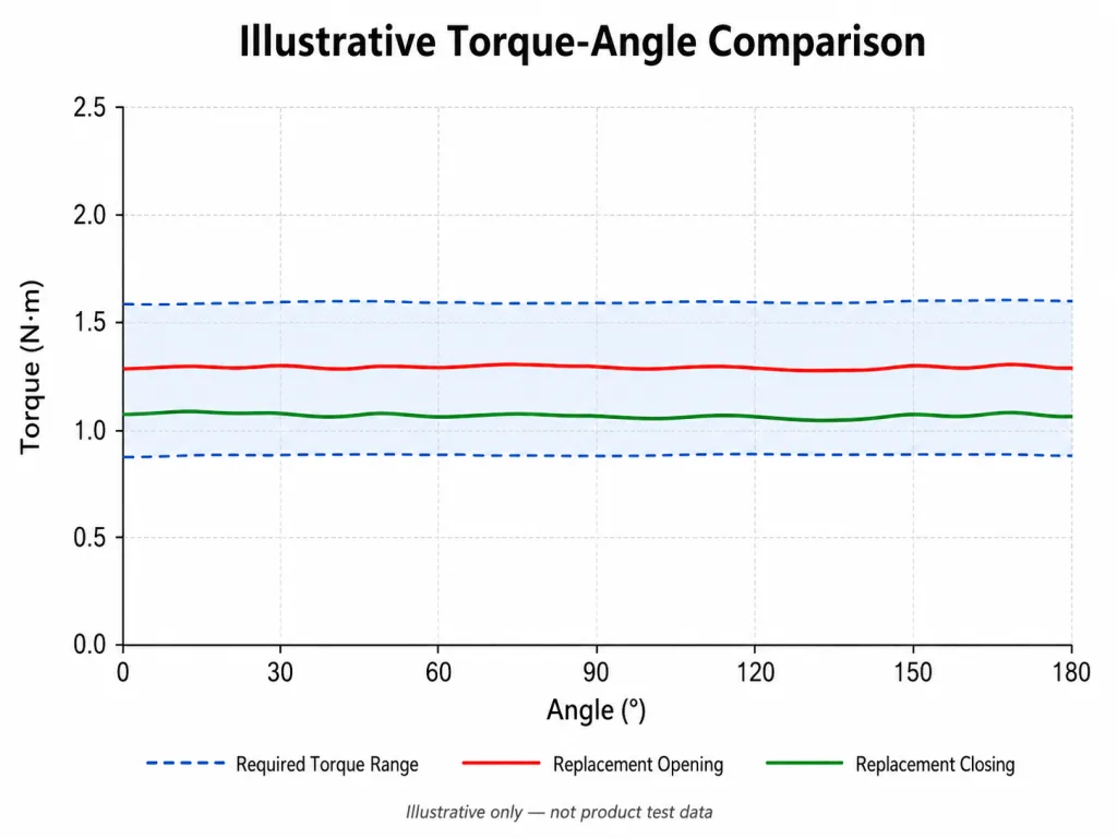
A single nominal torque value is rarely enough to cross-reference a position-control hinge. First define what the number means. Breakaway torque describes the peak needed to start movement after rest. Running torque describes resistance while moving. Holding torque describes the resistance available to keep the panel at a position. Opening and closing values may differ. Forward and reverse values are meaningless unless the viewing reference and installation orientation are shown.
Record the legacy behavior under a controlled set of conditions:
- Specimen state: unused, run-in, field-used, environmentally conditioned, or life-cycled
- Direction: opening and closing, or clockwise and counterclockwise from a defined viewing side
- Angular region: start angle, end angle, measurement points, and any excluded stop or detent zone
- Speed: controlled rotation speed rather than an undefined hand movement
- Dwell: rest time before breakaway or holding measurement
- Temperature: hinge temperature and conditioning time when the application is temperature-sensitive
- Output: peak, minimum, maximum, average, or complete torque-angle curve
- Variation: unit-to-unit range and, where hinges work in pairs, pair-to-pair behavior
The detailed fixture, sensor, lever-arm, and data-processing method belongs in the separate guide on how hinge torque is measured. For replacement work, the immediate requirement is comparability: test the legacy hinge and each candidate with the same definitions and conditions, then keep hinge-only results separate from complete-assembly operating force.
Same N·m does not mean same behavior. One value may describe symmetric running torque; another may describe a forward peak; a third may apply only after run-in at room temperature. Until the term and conditions are normalized, the numbers are not equivalent.
For a two-hinge panel, do not assume each hinge contributes exactly half of the total resistance. Bracket flex, axis misalignment, torque tolerance, and directional mismatch can make one hinge lead while the other drags. Test the proposed pair in the required A/B or left/right orientation, not only as two loose individual parts.
Worn Samples Can Set the Wrong Target
A used hinge is valuable evidence, but it answers a different question from an unused reference. It shows what survived, where wear developed, whether corrosion entered the mechanism, how fasteners moved, and how the real assembly loaded the part. It does not automatically show the torque that the original design intended.
Copying a worn sample can lock an existing failure into the new design. A field hinge that now measures 1.2 N·m may have started at 1.8 N·m. If the panel has been drifting for months, reproducing 1.2 N·m creates a replacement that is weak on day one. The opposite can also happen: contamination, corrosion, or a distorted bracket can raise measured resistance and make an overly stiff candidate appear correct.
Use the evidence in this order:
- Use the released requirement when it is complete and traceable.
- Use an unused retained sample to reconstruct original behavior.
- Use several field samples to understand wear and variation.
- Use the complete equipment to define the behavior that must be restored or improved.
- When the sources conflict, create a new engineering acceptance window rather than pretending the old value is known.
Label every measured sample with its part number, equipment serial or revision, service history if known, temperature, orientation, and test date. “Old hinge sample” is not enough traceability for a replacement decision.
Must Match, May Change
A replacement specification becomes manageable when every attribute is assigned one of three control levels: exact interchangeability, functional equivalence, or permitted change. This prevents buyers from demanding an expensive copy of details that do not matter while allowing critical differences to slip through.
| Control Level | Typical Attributes | Approval Evidence |
|---|---|---|
| Exact for a drop-in service part | Mounting-hole interface, axis location, handedness, required installation orientation, fastener access, closed and open envelope, assembly sequence | Controlled overlay drawing plus fit check on representative legacy equipment |
| Functionally equivalent | Opening and closing torque envelope, holding positions, hand force, radial and axial support, cycle retention, temperature behavior, corrosion and chemical suitability | Comparable test data and final-assembly sample validation |
| May change after review | Hidden internal mechanism, nonfunctional exterior radii, manufacturing process, supplier model code, packaging, cosmetic finish where appearance and environment remain acceptable | Supplier deviation list and documented OEM approval |
| May change only for new production | Hole pattern, bracket, fastener family, local reinforcement, cable route, stop location, door or frame cutout | Revised equipment drawing, updated assembly method, and new sample approval |
Material belongs in the functional-equivalence group unless the project requires the exact grade for regulatory, corrosion, welding, magnetic, appearance, or compatibility reasons. A different material may be acceptable only when the entire torque path and mounting interface remain suitable. A stainless exterior alone does not prove that the shaft, friction components, springs, bushings, or fasteners match the environment.
Three Replacement Routes
Once the must-match fields are clear, choose the smallest change that closes the gap and fits the supplier’s manufacturing capabilities. The lowest unit price is not always the lowest replacement cost. A cheap catalog hinge that forces a bracket redesign, cable reroute, new work instruction, and repeated testing can cost more than a modified platform with a higher part price.
| Route | Use It When | Main Commercial Advantage | Main Approval Risk | Supplier Return Needed |
|---|---|---|---|---|
| Catalog equivalent | A current model matches the interface, torque behavior, direction, environment, and lifecycle requirement | No dedicated tooling and usually the simplest supply route | A near-match may be approved from a catalog table without checking the installed system | Exact model drawing, deviation comparison, test conditions, and samples |
| Modified existing platform | The internal mechanism is suitable but torque, bracket, hole pattern, shaft end, stop, material, or finish needs a controlled change | Retains a known mechanism while adapting the equipment interface | A small external change can alter stiffness, load path, or torque after locking and assembly | Revised controlled drawing, changed-feature list, performance limits, sample and commercial boundaries |
| Custom replacement | The legacy geometry, torque curve, directionality, package density, or installation constraint cannot be met by an existing platform | Can preserve a difficult installed interface or consolidate several obsolete variants | Tooling, validation, ownership, minimum volume, and change-control terms must be agreed before release | Feasibility response, preliminary drawing, development assumptions, tooling scope, sample plan, and production controls |
Do not force a catalog equivalent when the only match is cosmetic. Do not open custom tooling merely because the old supplier used a unique part number. The right route is the one that meets the controlled requirement with the least total equipment change and an acceptable supply risk.
The Same 2.0 N·m, a Different Machine
The holes line up. The lid still behaves differently.
Consider an existing operator panel that uses two factory-set hinges. The legacy data sheet lists 2.0 N·m, and a proposed replacement carries the same nominal value and nearly the same footprint. The comparison looks complete until direction and axis location are checked. The legacy assembly provides similar resistance in both directions. The candidate provides higher resistance while opening and lower resistance while closing. Its axis also sits slightly farther from the panel datum.
On the bench, both parts feel acceptable. In the machine, the replacement panel is harder to lift near closed, easier to push downward through the working range, and places a different bend in the cable bundle. The problem is not that the candidate hinge is defective. The equivalence definition was too narrow: “2.0 N·m and same holes” did not control the motion the equipment needed.
This is an illustrative engineering scenario, not a customer project record or product test claim.
The Replacement Inquiry Package
A supplier cannot quote a reliable discontinued torque hinge replacement from one photo and an old part number. The inquiry should make the replacement boundary visible: what must remain interchangeable, what can change, and which evidence is still missing.
DISCONTINUED TORQUE HINGE REPLACEMENT REQUEST
------------------------------------------------
LEGACY IDENTITY
Equipment / assembly:
Equipment revision:
Legacy supplier:
Legacy supplier part number:
Customer part number:
Legacy drawing / revision:
Replacement purpose: service / new production / both

PHYSICAL EVIDENCE
Released 2D drawing available: yes / no
3D model available: yes / no
Unused retained sample available: yes / no
Used samples available: quantity and known service history
Installed assembly available for review: yes / no
Photos attached: closed / intermediate / open / mounting detail

FUNCTION
Panel or lid complete mass:
Center-of-gravity location if known:
Number of hinges:
Required opening range:
Required holding angles or free-stop range:
Opening torque requirement:
Closing torque requirement:
Breakaway / running / holding definition:
One-way, asymmetric, symmetric, detent, or adjustable behavior:
Acceptable hand force and measurement point:
Mechanical stop or released zone:
Cable, gasket, latch, or hose forces:

INTERFACE
Hinge-axis location from equipment datums:
Hole pattern and tolerances:
Leaf / bracket / shaft configuration:
Handing and installation orientation:
Fastener and mounting substrate:
Available installation and motion envelope:
Permitted equipment changes:
Drop-in service interchangeability required: yes / no

DUTY AND ENVIRONMENT
Expected cycle requirement:
Torque-retention requirement:
Operating temperature:
Indoor / outdoor / washdown / coastal / chemical / dusty:
Material or finish constraints:
Radial / axial / shock / vibration concerns:
Required certificates or test evidence:

COMMERCIAL
Service quantity:
Prototype / sample quantity:
Expected annual production volume:
Target sample date:
Target production date:
Tooling ownership or exclusivity requirement:
Approved deviations must be listed: yes
What the Supplier Should Return
Ask for a technical response that can be reviewed, not only a quotation:
- Proposed model and controlled drawing revision
- Side-by-side deviation list against the legacy interface and performance requirement
- Torque definition, tolerance, direction, angular window, speed, dwell, temperature, conditioning, and reported data type
- Torque-angle data or limits for both directions where direction matters
- Material and finish for the body, shaft, functional components, and supplied fasteners where relevant
- Radial, axial, cycle, temperature, corrosion, or other evidence needed by the application
- Required mounting orientation, pair arrangement, adjustment, locking, stop, and installation notes
- Sample availability and which features will remain preliminary until sample approval
- Tooling, MOQ, lead-time, ownership, and change-control boundaries if modification or custom development is proposed
When reviewing candidate data, use the same discipline described in the guide to compare constant torque hinge specifications. A supplier that reports a different torque term or test condition should not be rejected automatically, but the difference must be identified before the numbers are compared.
Sample Validation in the Final Assembly
A candidate is not approved when it fits the drawing. It is approved when the controlled sample performs in the equipment and the result can be repeated. Define the acceptance criteria before the sample arrives; otherwise the team will judge it by whichever feature is most noticeable on the day.
- Confirm identity. Record the supplier model, drawing revision, sample marking, torque configuration, finish, handedness, and any preliminary deviations.
- Install without forcing alignment. The hinge should seat on the intended surfaces with the approved fasteners. Do not use screw tightening to pull a mismatched axis or distorted bracket into place.
- Check the complete motion envelope. Move through the full opening range and inspect interference, cable bend, gasket behavior, latch clearance, stop contact, and tool access.
- Verify position holding. Test every required working angle with the complete production-intent load. Look for drift after movement and after the defined dwell period.
- Measure operating effort. Use the real handle or contact point and compare opening and closing effort against the approved window. A hinge can hold correctly and still be unacceptable to the operator.
- Evaluate the hinge pair or set. Use the production orientation and spacing. Check panel twist, nonuniform motion, noise, sudden release, and whether one hinge carries more of the movement.
- Repeat under relevant conditions. Where risk justifies it, evaluate minimum, room, and maximum temperature; vibration or shock; contamination; cleaning exposure; and the required cycle/torque-retention condition.
- Test service replacement. For installed equipment, confirm that a technician can remove the old hinge and install the new one using the intended access, tools, fasteners, and work instruction without uncontrolled field modification.
Use representative equipment tolerances, not only the easiest prototype. Where several legacy revisions remain in service, fit the candidate to each approved interface or state clearly which revisions it replaces. Record before-and-after gaps, holding behavior, torque or hand-force data, sample identity, test conditions, and any adjustment or locking operation.
After approval, update the BOM, cross-reference record, released drawing, incoming inspection criteria, assembly instruction, and effectivity date or serial range. Preserve the legacy part number in the record so service and quality teams can trace what the new hinge replaces. This change-control step should be short, but it must not be informal.
Questions About Obsolete Torque Hinges
Can a hinge with the same N·m rating replace the old one?
Not by that value alone. Confirm the torque term, tolerance, opening and closing directions, angle, speed, dwell, temperature, specimen condition, and torque retained after cycling. The mounting axis, load capability, orientation, and installed behavior must also match the equipment requirement.
Can a manufacturer reproduce the hinge from a used sample?
A used sample can support reverse engineering of geometry and reveal wear or failure evidence. It should not be the only source for original torque because service wear, corrosion, contamination, bracket distortion, and unknown temperature history may have changed its behavior. Combine it with drawings, an unused sample when available, and the required equipment function.
What if the original hinge drawing is unavailable?
Create a new controlled replacement specification from physical measurement, assembly datums, multiple samples, photographs, old purchase records, and functional testing. Mark reconstructed dimensions and assumptions clearly. The goal is not to claim the original design is known; it is to release a new requirement that the successor can be inspected against.
Should the equipment hole pattern be changed to use a standard hinge?
It can be a practical new-production solution when the revised interface reduces tooling, cost, or supply risk and the door, frame, reinforcement, cable path, and assembly process can be revalidated. It is usually unsuitable for a service replacement unless a controlled retrofit kit and field procedure are part of the project.
Can an adjustable hinge replace a discontinued fixed-torque hinge?
Possibly, when its geometry, usable torque range, direction, environment, and lifecycle behavior fit the application. The production setting, adjustment condition, locking method, post-lock torque, inspection method, and field-adjustment permission must then be controlled. Adjustability solves uncertainty only when the setting process is repeatable.
Send the Legacy Hinge Data for a Replacement Review
Provide the old part number, available drawing, closed and open installation photos, hinge quantity and orientation, panel mass, required angles, unused or used sample status, operating environment, service quantity, annual production demand, and the changes your equipment can accept. HSP can review whether the requirement is better suited to a current platform, a controlled modification, or a custom replacement—and identify the missing inputs that must be resolved before samples are approved.