-
+86 13720060320
-
lanna@haitangs.com

How to Specify Adjustable Torque Hinge Range and Locking
Two suppliers can publish the same adjustable torque range and still offer different usable products.
One hinge may hold a stable setting through the middle of the adjuster travel and remain close to that value after locking. Another may reach the stated maximum only near the mechanical endpoint, where a small movement of the screw causes a large change in torque.
That is why an adjustable torque hinge specification cannot stop at a minimum and maximum value. It must define the usable setting window, adjustment access, locking condition, permitted post-lock shift, and the evidence the supplier must return.
If the mechanism decision is still open, begin with the constant vs. adjustable torque hinge guide.
Usable RangeApprove an operating window, not only mechanical endpoints.
Lock ConditionMeasure the finished setting after the lock is applied.
Production ControlDefine how the factory reproduces and verifies the setting.
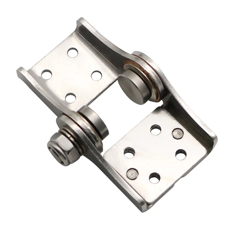
Catalog Range Is Not the Usable Range
A catalog may show one lower value and one upper value. Those numbers can describe mechanical capability, a tested output range, or simply the available settings of one sample. They do not automatically define the range that should be released on an OEM drawing.
| Range Term | Meaning | Buyer Action |
|---|---|---|
| Mechanical travel | The physical movement available in the screw, nut, cam, clamp, or compression mechanism | Ask whether the full travel is approved for normal operation. |
| Published range | The minimum and maximum torque reported under a stated supplier condition | Request direction, angle, temperature, speed, and lock condition. |
| Usable range | The portion that meets holding, operator-force, repeatability, and retention requirements | Approve this range, not the mechanical endpoints. |
| Production window | The allowed factory setting around the nominal target | Define a setting tolerance and inspection method. |
| Service reserve | Adjustment room remaining above and below the production setting | Keep the nominal setting away from an endpoint unless endpoint use is validated. |
A wide published range can still be a poor fit. The project target may sit too close to the upper endpoint. The lower end may remain too stiff for the operator. The range may apply only in one direction, or the reported value may be breakaway torque rather than running torque.
Mechanical End
Published Range
Usable Range
Production Window
Mechanical End
Set the Window From the Assembly
The usable range should surround the torque required by the complete panel. That target comes from panel mass, center-of-gravity distance, hinge quantity, operating angle, cable resistance, gasket resistance, and acceptable hand force. The detailed calculation belongs in the torque hinge calculation guide.
Once the target is known, place it inside the adjustment range with enough reserve for production variation and expected torque change. Do not define the released setting as “maximum,” “fully tightened,” or “three turns from loose” unless the exact model, reference position, adjustment response, and inspection method are controlled.
Release rule: Specify the approved operating window and nominal production setting. Do not approve the hinge only because the catalog maximum exceeds the calculated target.
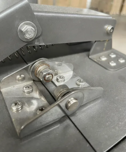
Adjustment Access in the Assembly
An adjustment feature shown on a supplier drawing may be inaccessible after installation. A cabinet return, bezel, cover, cable duct, gasket retainer, display housing, or adjacent bracket can block the tool even when the hinge itself fits.
The specification should identify the adjustment interface without turning into a field-adjustment procedure.
The supplier must also state which direction increases or decreases torque for the exact model and orientation. Do not publish a universal clockwise or counterclockwise instruction.
| Field | Supplier Definition | Drawing Check |
|---|---|---|
| Adjustment feature | Screw, nut, cam, clamp, compression element, or model-specific mechanism | Do not confuse the adjuster with a mounting or retention fastener. |
| Tool | Tool type, engagement depth, and access direction | Show the complete tool envelope in the installed assembly. |
| Adjustment condition | Loaded, supported, unloaded, open, closed, or at a stated angle | Confirm the final product can be placed in that condition. |
| Permitted travel | Approved adjuster movement and endpoint restrictions | Provide a visible or measurable limit. |
| Service access | Factory-only or field-adjustable | Do not assume later access if a cover seals the feature. |
Detailed support, turning, balancing, and troubleshooting steps remain on the torque hinge adjustment procedure. This page only defines the conditions that procedure must follow.
Locking Method and Post-Lock Shift
Locking is part of the torque mechanism. Tightening a locknut, applying a separate set screw, adding thread-locking material, or engaging an indexed feature can change preload and move the final torque away from the unlocked setting.
| Locking Approach | Specification Input | Key Risk |
|---|---|---|
| Locknut or jam nut | Holding method, tightening requirement, access, and post-lock recheck | The adjuster can rotate while the nut is tightened. |
| Separate set screw | Contact location, tightening requirement, and permitted thread condition | Excess contact pressure can mark or shift the adjuster. |
| Thread-locking material | Approved material, application amount, cure condition, and serviceability | The material can change adjustment feel or prevent later service. |
| Indexed or captive feature | Available positions, engagement confirmation, and setting identification | The required setting may fall between available positions. |
| Permanent production lock | Approved process, inspection evidence, and rework limit | The hinge may no longer be field-adjustable. |
The approved torque should represent the finished locked condition. Record the unlocked value when it helps diagnose process shift, but release the hinge against a maximum permitted difference between the pre-lock and post-lock measurements.
Long-term torque retention after cycling, vibration, or temperature exposure is a separate qualification task. Transfer that work to the torque hinge cycle-life and retention guide.
Adjustment Resolution and Production Control
A range is not production-ready until the factory can set and identify a repeatable position. The buyer needs to know how sensitive the output is to a small movement of the adjuster.
Adjustment Resolution
Torque change per turn, partial turn, index, mark, or measured setting interval.
Nominal Setting
The approved production target for the exact model and application.
Setting Tolerance
The permitted variation around the nominal production target.
Position Reference
A mark, dimension, index, measured torque, or other controlled method.
Endpoint Reserve
Remaining travel above and below the production setting.
Inspection Method
How the factory verifies the finished locked result.
A simple turn count can work only when the starting reference, thread travel, model revision, direction, loaded condition, and resulting torque relationship are controlled. Without those conditions, “two turns” is not a transferable specification.
The production check should measure the output that matters to the assembly. Depending on the project, that may be running torque through a defined angle, holding behavior at a stated position, or operator force at a known handle distance.
Supplier Data Required
The supplier return should focus on adjustable-hinge evidence, not a generic catalog sheet.
| Required Evidence | Why It Is Needed |
|---|---|
| Controlled model drawing and revision | Links the range and locking data to the exact configuration. |
| Adjuster and lock-feature identification | Prevents the wrong fastener from being used. |
| Mechanical travel and endpoint limits | Shows where normal operation is restricted. |
| Published and recommended usable range | Separates tested capability from the working window. |
| Torque versus adjustment position | Shows sensitivity and unstable regions. |
| Measurement condition | Defines direction, angle, speed, temperature, and lock state. |
| Pre-lock and post-lock data | Quantifies shift caused by locking. |
| Production setting reference | Allows repeatable factory inspection. |
A generic torque-angle curve can support the review, but the essential evidence here is the relationship between adjuster position, usable torque, locking, and the finished production setting.
Adjustable Torque Hinge RFQ Block
Use these fields after the torque target and hinge architecture have already been established. Leave unknown values blank instead of inventing them.
Application
- Application and moving panel
- Hinge quantity
- Operating angle
- Required torque term
- Usable range per hinge
Production Setting
- Nominal setting
- Allowed tolerance
- Reserve above and below nominal
- Production setting reference
- Final inspection method
Adjustment Interface
- Adjustment feature
- Tool and access envelope
- Adjustment condition
- Permitted travel
- Field readjustment required
Locking and Supplier Return
- Locking method and instruction
- Maximum post-lock shift
- Model and drawing revision
- Pre-lock and post-lock data
- Retention report reference
Send the Range and Locking Inputs
Send the torque window, nominal production setting, adjustment-access limits, locking condition, hinge quantity, panel drawing, and required service reserve.
Adjustable Torque Hinge Questions
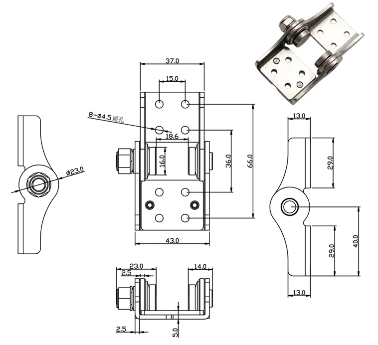
Technical review and limitation note: The dimensional drawing and photographs on this page illustrate a specific or representative adjustable torque hinge. Usable range, adjustment direction, locking instruction, tool access, and post-lock torque shift remain model- and project-specific. Do not transfer dimensions or adjustment instructions between models without a controlled drawing and supplier confirmation.