-
+86 13720060320
-
lanna@haitangs.com

How to Select Vehicle Compartment Door Hinges for Trucks, Trailers, and Mobile Equipment
A compartment door can close cleanly during assembly and start rubbing, leaking, or rattling after the truck, trailer, or mobile equipment enters service.
The hinge may not be broken. The body, trailer frame, or equipment enclosure can twist over curbs, uneven ground, towing inputs, and deployed supports. The mounting edge can flex, the lower joint can collect water and grit, and the latch can pull a shifted door back against the gasket. The closed appearance can therefore hide movement elsewhere in the door system.
Vehicle compartment door hinges must therefore be selected as part of a moving door system. Door orientation, center of gravity, body structure, hinge axis, gasket path, latch pull-in, drainage, road vibration, and service access all affect the result.
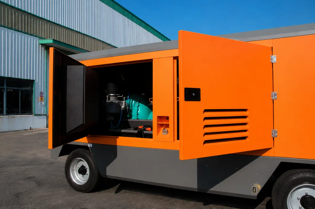
This guide covers exterior storage, tool, engine, electrical, hydraulic, and equipment compartment doors on service trucks, utility bodies, emergency vehicles, trailers, and towable or self-propelled mobile equipment. Typical applications include mechanic trucks, utility-service vehicles, mobile compressors, generators, pumps, lighting towers, and similar road-transported equipment. Railcar doors, passenger doors, cargo-body rear doors, hoods, tailgates, interior cabinetry, and latch-model selection belong to separate pages.
The Door Still Latched, but the Gap Moved
A workshop inspection usually confirms that the door opens, clears the body, reaches the latch, and compresses the gasket. The vehicle is stationary and supported on a level floor. The door frame is also close to its nominal shape.
Road service changes that condition. A utility body can twist when one wheel climbs a curb, when stabilizers are deployed unevenly, when the chassis is loaded asymmetrically, or when the vehicle crosses broken ground. Small repeated movement at the hinge bracket or mounting holes can then change the door position.
The latch hid movement at the lower hinge
A side compartment door returned from a road test with no missing hardware and no visible pin movement. It still latched. The lower hinge-side gap had narrowed, however, and the latch-side gasket showed heavier compression. One mounting joint had shifted slightly while the compression latch pulled the free edge back into the opening.
A stronger latch would have increased the pull-in load without correcting the hinge line. The useful evidence was the unloaded door gap, hinge position, fastener witness marks, gasket pattern, and the difference between the door position before and after latch pull-in.
This is an illustrative engineering scenario, not a customer project record or product test claim.
Selection boundary: the hinge is acceptable only when the complete compartment door returns to its controlled position after body movement, vibration, opening, closing, and normal service. “The door still shuts” is not enough.
Door Direction Comes Before Hinge Size
The first decision is how the compartment must be used. A vertical side-opening door, an upward-opening door, a downward work-surface door, and a removable panel place different loads on the hinge and create different operator risks.
| Door Arrangement | Service Benefit | Hinge-System Requirement | Main Risk to Control |
|---|---|---|---|
| Side-opening vertical door | Simple access and familiar operation | Stable vertical axis, controlled sag, independent opening stop | Door swing into traffic, workers, adjacent compartments, or vehicle equipment |
| Top-hinged upward door | Door stays above the opening and can provide weather cover | Axial support, assisted lift or hold-open device, positive retention | Unexpected closing, asymmetric gas-spring force, water entering the upper hinge line |
| Bottom-hinged door | Can become a temporary shelf or service surface | Defined stop or support cables and reinforced hinge edge | Operator overload, cable shock, door used as a step |
| Lift-off or removable panel | Full access for module replacement or deep service | Removal clearance, positive anti-lift control, safe handling, repeatable datum | Unintended disengagement, loose hardware, difficult reinstallation |
| Multiple small access doors | Separates tools and equipment by task | Consistent handedness, repeatable gaps, compatible latch and gasket geometry | Tolerance accumulation across many doors and field-replacement mismatch |
The same vehicle can use more than one arrangement, but each door should have one defined service task. Do not choose a hinge family only because it is already used elsewhere on the body.
Side-opening doors usually create the simplest hinge load path, but their swing can obstruct a worker standing beside the vehicle. Top-hinged doors clear the opening more effectively, yet their hinge pins and supports see a different combination of radial and axial load. The door also needs a controlled hold-open method. A gas spring that works on level ground may produce a different handling condition when the vehicle is parked on a slope or when temperature changes its output.
Bottom-hinged doors create another conflict. They can become a useful work surface, which encourages operators to place tools, parts, or body weight on them. The hinge and support cables must therefore be reviewed against the real service behavior, not only the door’s own weight. Where the door must never be used as a step, the label and the physical support design should communicate the same restriction.
Use the Complete Door Mass
The finished door includes more than the outer skin. Inner panels, reinforcement, shelves, windows, insulation, latch rods, grab handles, reflectors, mounted tools, warning plates, seals, and trim can move the center of gravity away from the hinge axis.
Use the production-intent mass and center of gravity. A light fabrication sample can understate both the static moment and the effect of road acceleration. The final hinge reactions also depend on hinge spacing, door stiffness, the mounting edge, and whether the latch corrects sag at the free side.
Hinges in a pair do not automatically share the load equally. A flexible door or body flange can concentrate the correction at one hinge while the other follows the distorted structure.
Include realistic service loads in the review. A technician may pull on the open door, hang a tool bag from the inner panel, use a bottom-hinged door as a temporary shelf, or allow an assisted door to reach the stop quickly. These actions do not become acceptable merely because they are difficult to prevent. They should either be included in the design condition or excluded through a clear operating boundary and a separate support feature.
Hinge spacing also affects more than nominal load. Increasing the distance between the upper and lower hinges can reduce the reaction needed to resist the door moment, but only when the mounting structure between them remains stiff and the axes stay aligned. A widely spaced pair on a flexible flange can still bind because the body moves the centers relative to each other.
For the detailed static moment, hinge quantity, spacing, and reinforcement calculation, use the heavy enclosure door hinge guide. This page applies that baseline to a moving commercial-vehicle body.
Vehicle Compartment Door Hinges Under Body Twist
A service body is mounted on a chassis that moves. Even when the compartment opening is rigid locally, the surrounding structure can rack as the vehicle is loaded, parked on uneven ground, lifted, towed, or driven over rough surfaces.
The critical question is not whether the body flexes. It is whether that movement changes the relative position of the upper hinge, lower hinge, latch keeper, and gasket land enough to create binding or uneven compression.
Draw the hinge centers from body datums that can be inspected after assembly. Include the door frame, body flange, reinforcement, weld sequence, fastener slots, and any adjustable bracket. When an adjustment is necessary, define the released position and how it will be locked.
Measure the door in more than one vehicle condition when body movement is credible. Useful comparisons can include the unloaded body on a level floor, the normal operating load, one wheel or stabilizer creating a diagonal body input, and the final latched condition. The project does not need an invented universal twist value. It needs a repeatable condition that represents how the compartment structure can move in service.
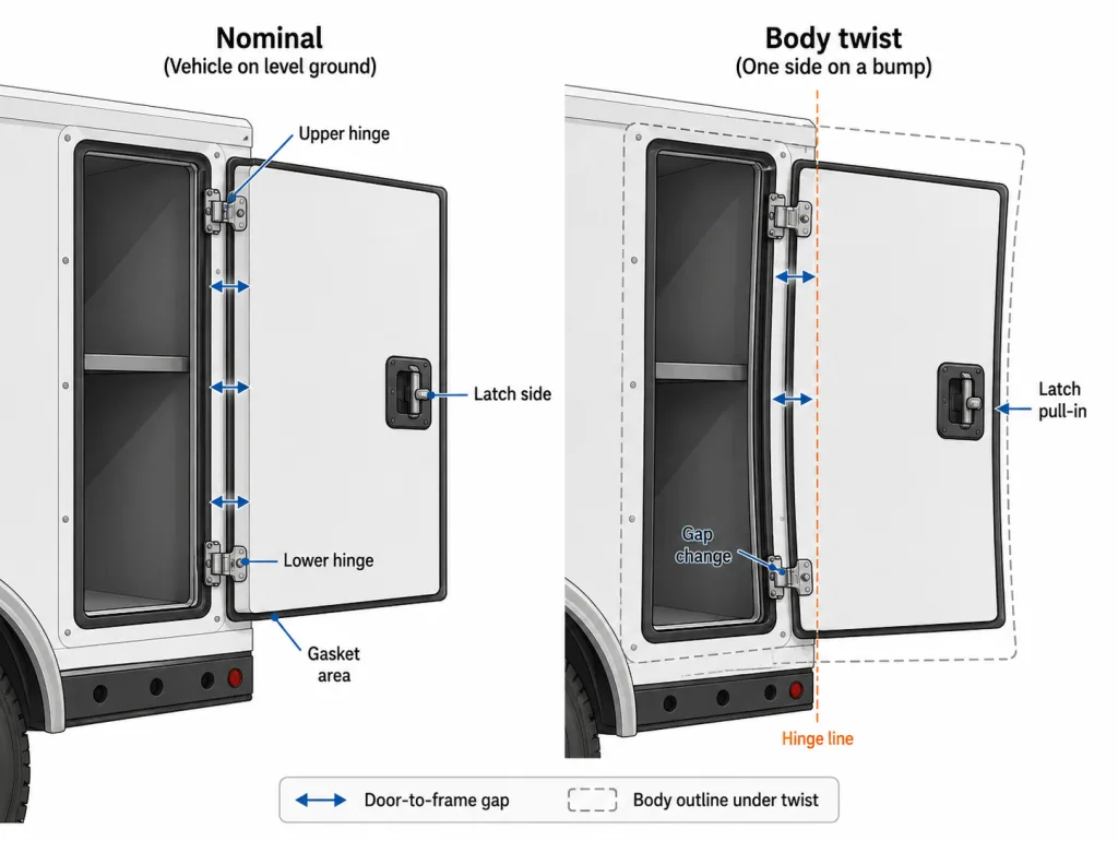
The unloaded door position matters because the latch can hide the change. Record the hinge-side and latch-side gaps before full pull-in, then record how far the latch moves the free edge. A door that becomes aligned only after substantial latch correction is transferring body distortion into the gasket, keeper, and hinge joint.
Hinge Axis, Gasket, and Latch Pull-In
The hinge axis controls how the door approaches the gasket. An offset can help the door clear a raised seal or outer flange during opening, but it also changes the moment at the bracket and the path of the hinge-side edge.
Review the closed door in section. Show the pin centerline, door and frame datums, gasket profile, latch pull-in direction, hinge-side clearance, and the position where compression begins. A front view alone cannot show whether the door drags across the gasket or rotates away cleanly.
The latch should compress the gasket after the hinge system has returned the door to its controlled position. It should not lift a sagging corner or pull a twisted panel sideways on every closing cycle.
Check the hinge-side sweep through the first part of opening. Raised bulb seals, formed drip rails, and overlapping flanges can contact the door edge before the panel has rotated far enough to move away. Repeated dragging can tear the gasket, polish the door edge, or add opening force that is incorrectly blamed on the hinge pin.
For doors with more than one latch, compare the compression at each locking point. A rigid linkage can reach its handle position while one keeper remains lightly loaded and another is over-compressed. The hinge axis and door stiffness determine how that imbalance is distributed around the perimeter.
| Observed Condition | Possible Hinge-System Cause | Evidence to Check | Next Action |
|---|---|---|---|
| Low compression at the lower hinge corner | Door sag, lower bracket movement, flexible mounting edge | Unlatched gap, bracket witness marks, hinge-axis position | Correct the load path before increasing latch preload |
| Heavy latch-side compression | Latch is rotating the door around the hinge line | Compare unloaded and fully latched door positions | Reset axis, keeper, and gasket relationship |
| Door rubs only after body loading | Upper and lower hinge centers move relative to each other | Measure body and door datums in the loaded condition | Stiffen or relocate the mounting structure |
| Gasket tears at the hinge side | Opening sweep drags the door edge across the seal | Section view of axis, offset, and gasket profile | Revise axis offset or seal geometry |
| Rattle with the latch closed | Closed play at the hinge or mounting joint | Pin clearance, fastener movement, bracket stiffness | Identify the moving interface before changing latch setting |
Fixed, Concealed, or Lift-Off?
The best architecture is the one that remains inspectable and controlled in the real vehicle location. Appearance matters, but it cannot replace access to the pin, fasteners, drainage path, and adjustment points.
Surface-Mounted Fixed Hinges
A fixed surface-mounted hinge makes the load path and service condition visible. It is practical for steel or aluminum service bodies when the bracket, fasteners, welds, and lower drainage area can be inspected. Exterior placement also exposes the joint to spray, impact, and tampering.
Concealed or Internal Hinges
An internal hinge supports a flush exterior and protects the pin and fasteners from direct access. The trade-off is a hidden bracket cavity that may collect water or become difficult to adjust after shelves, wiring, or liners are installed.
Lift-Off and Removable Doors
A removable door can clear the full service opening, but road shock must not act in the disengagement direction without positive control. The design needs removal clearance, an anti-lift feature, a panel support method, captive parts, and a repeatable reinstallation datum.
Removal should also be reviewed with the compartment loaded. Shelves, drawers, wiring, hoses, and stored tools can block the lift path or the technician’s grip. A door that can be removed from an empty prototype may become impractical after the body is fully equipped. When the door carries wiring, lighting, or a bonding connection, the release sequence must prevent the cable from becoming the lifting restraint.
Use the lift-off hinge clearance and pin-retention guide when the compartment door must be removable.
Exact Product Data Comes Later
After the architecture and mounting conditions are defined, an exact product page can be used to confirm dimensions, hole pattern, material, and finish. The published heavy-duty equipment hinge dimensions are one model-level reference, not proof that the hinge is released for every vehicle compartment.
Mounting Edge and Joint Stability
A strong hinge mounted to a flexible flange still produces a weak door system. Thin skins can dish around bolts or rivet nuts. Welded brackets can move during fabrication. Slotted holes can simplify alignment and then become a path for road-induced movement if the joint is not locked correctly.
Identify the real load-carrying structure: formed return, internal plate, tube frame, extrusion, welded bracket, or reinforced composite insert. The drawing should show how the hinge reaction reaches that structure rather than stopping at the visible panel skin.
For bolted joints, control the complete stack: fastener, washer, thread engagement, insert or nut, surface finish, sealant, and installation method. For welded joints, control the tack sequence, heat input, access, and final pin-center alignment.
Bolt-on and weld-on arrangements solve different production problems. A bolt-on hinge supports adjustment and replacement, but the joint must resist micro-movement without crushing thin material or losing preload. A weld-on bracket can create a direct structural path in a steel body, yet weld distortion can move the pin center before the door is fitted. Neither method is inherently better without the body section, manufacturing process, service plan, and alignment controls.
Mixed-material bodies need an additional review. Stainless hardware on an aluminum body, plated carbon steel against a coated panel, or a sealed fastener stack can create galvanic, coating, and water-trap questions. The mounting specification should identify isolators, sealants, finish restoration, and inspection access where they are required by the project.
For backing plates, rivet nuts, thread engagement, edge distance, and thin-panel reinforcement, use the thin sheet-metal hinge mounting guide.
Do not solve mounting-edge movement by selecting a larger hinge alone. The hinge can survive while the body flange, fastener holes, bracket, or weld continues to move.
Road Spray and the Lower Hinge
Exterior vehicle compartments collect water, grit, road salt, wash residue, and debris. The lower hinge often remains wet longer because moisture settles around the pin, behind the leaf, under fastener heads, and inside body pockets.
Review the complete material system: leaf, pin, bushing or bearing, washer, retainer, fasteners, weld, coating, lubricant, bracket, and adjacent body material. A stainless leaf does not define the hidden pin, retainer, or fastener.
Provide a drainage path in the installed orientation. Avoid pockets that direct water into the compartment wall, insulation, electrical area, or mounting holes. The joint should remain accessible for cleaning and inspection without removing unrelated body equipment.
Stone impact and tool contact can damage a protective finish at edges and fasteners. Where the lower hinge is expected to be a service item, make replacement possible without cutting apart the compartment structure.
Upper and lower hinges may need different inspection attention even when they share one part number. The upper joint can see direct runoff from a drip rail or roof edge. The lower joint can remain submerged in trapped moisture and abrasive grit. The inspection plan should follow the installed water path rather than treating both positions as identical.
Corrosion evidence must be tied to the exact assembly. A finish name or material grade does not describe cut edges, welded areas, damaged coating, fastener contact, lubricant washout, or debris trapped behind a leaf. The vehicle builder still needs project-specific acceptance criteria for appearance, movement, retention, and replacement.
Stops, Hold-Open Devices, and Gas Springs
The hinge should not become the accidental end stop. A door that reaches hinge end travel at speed can bend the leaf, loosen the mounting edge, or change the pin support even when the hinge still rotates.
Side-opening doors need a stop or restraint that prevents contact with adjacent compartments, wheels, outriggers, mirrors, traffic, or workers. Upward-opening doors need a hold-open method that remains stable across temperature, vehicle angle, and real door mass.
A gas spring can reduce operator force, but an asymmetric installation can twist a wide door and increase load at one hinge. Support cables on a bottom-hinged door can also shock the hinge line when their slack is taken up.
Draw the complete motion envelope. Include the stop, stay, gas spring, support cable, handle, latch rods, wiring, grounding strap, and the technician’s working position. The device that controls the opening angle needs its own structural load path.
Hold-open devices also affect field replacement. A gas spring, spring stay, or cable can preload the door during hinge removal and can move the panel unexpectedly when one fastener is released. The service drawing should identify the safe support point and the sequence for unloading these components before the hinge joint is separated.
Installed Road-Duty Validation
A loose hinge sample cannot reproduce body twist, paired-axis error, gasket compression, latch pull-in, opening-stop impact, gas-spring force, road spray, or the actual mounting edge. Validate the production-intent compartment door or a documented fixture that reproduces those interfaces.
The validation plan should state what each condition is meant to reveal. Repeated opening can expose wear and alignment drift. Road or fixture vibration can reveal joint movement and rattle. A body-twist condition can reveal sensitivity to chassis position. Water and contamination exposure can reveal drainage and lower-joint binding. One test should not be described as proof of every service condition.
Baseline Without Latch Correction
Record the hinge and door revisions, upper and lower hinge positions, mounting-slot and fastener witness marks, unloaded door gaps, latch and keeper contact, gasket pattern, operating force, stop, hold-open device, and lower drainage area.
Operate the Real Service Sequence
Open and close the door through the approved range. Use the actual hold-open device, remove the door when removal is part of service, and operate the vehicle or test fixture through the project-defined road, vibration, body-twist, and environmental conditions.
Follow the Movement Path
Inspect the pin and retainer, but do not stop there. Look for fastener or slot movement, fretting, bracket deformation, weld changes, increased play, finish damage, water traps, gap change, gasket shift, and a difference in latch pull-in.
Return to the Controlled Closed Position
After exposure and service, confirm that the door returns to its released datum before full latch pull-in. Recheck the complete perimeter, opening force, stop, gas spring or stay, cable routes, lock operation, and access to stored equipment.
Write the acceptance criteria before testing. “No hardware missing” and “the latch still closes” do not prove that the compartment door remained aligned.
Useful acceptance fields are measurable and connected to the failure path: permitted unloaded-gap change, permitted slot or fastener movement, pin-retention position, operating-force change, gasket-contact pattern, water path, stop condition, hold-open function, and repeatability after removal and reinstallation. Values remain project-specific unless an exact model test report provides them.
Release Evidence for the Exact Door
The release package should connect one hinge revision to one vehicle-body interface and one validation condition. A general description such as “heavy-duty stainless hinge” is not enough to control a replacement or production change.
Door and Service Task
- Vehicle and compartment location
- Door orientation and opening direction
- Complete mass and center of gravity
- Service angle, removal task, and handling method
Hinge Construction
- Part number and drawing revision
- Pin, bushing or bearing, thrust support, and retention
- Leaf, bracket, fastener, weld, material, and finish
- Opening limit and adjustment features
Body Interface
- Upper and lower hinge datums
- Reinforcement and mounting-edge section
- Latch, keeper, gasket, stop, and hold-open device
- Drainage path and lower-hinge access
Installed Validation
- Baseline gaps and latch pull-in
- Road, vibration, body-twist, and environmental condition
- Post-test movement and functional inspection
- Changes requiring review or revalidation
Send the Compartment Door Section and Body Interface
Provide the complete door mass, center of gravity, hinge spacing, mounting section, opening direction, gasket and latch layout, drainage exposure, hold-open device, and the installed evidence required by the project. HSP can review the hinge architecture and model-level drawing inputs before sampling.
Frequently Asked Questions About Vehicle Compartment Door Hinges
What type of hinge is best for a vehicle compartment door?
There is no single hinge type that is best for every compartment. Selection depends on the door orientation, complete mass, center of gravity, hinge spacing, mounting-edge stiffness, opening direction, gasket path, latch pull-in, road exposure, and required service access. The hinge architecture should be defined before comparing individual product dimensions.
Can a stronger latch correct a sagging compartment door?
A stronger latch may pull the free edge back into the opening, but it does not correct a moved hinge axis, flexible mounting edge, loose joint, or distorted door. It can instead increase keeper load and uneven gasket compression. Check the unloaded door gaps and hinge positions before increasing latch preload.
How should vehicle body twist be considered during hinge selection?
Compare the upper hinge, lower hinge, latch keeper, gasket land, and door gaps under representative vehicle conditions. These may include the unloaded body on a level floor, normal operating load, and a project-defined diagonal or stabilizer input. The goal is to identify whether body movement changes the hinge centers enough to cause binding, rubbing, or uneven sealing.
What must be checked for a top-hinged compartment door?
A top-hinged door requires review of radial and axial hinge loads, complete door mass, hold-open stability, gas-spring geometry, opening stops, water runoff, and safe service access. A gas spring should not be treated as the only safety control, and an asymmetric support arrangement should be checked for door twist and unequal hinge loading.
When is a lift-off hinge suitable for a vehicle compartment?
A lift-off hinge is useful when the complete door must be removed for module replacement or deep service access. The design still needs adequate removal clearance, positive anti-lift control, captive or controlled hardware, a safe panel-handling method, and a repeatable reinstallation datum. Wiring, lighting, hoses, or bonding straps must not become unintended lifting restraints.
Why does the lower compartment-door hinge often bind or corrode first?
The lower hinge can retain road spray, salt, grit, wash residue, and moisture around the pin, leaf, fasteners, and body pocket. Material grade alone does not define the corrosion behavior of the complete joint. Drainage, coating damage, mixed materials, lubricant condition, debris traps, and inspection access must also be reviewed in the installed orientation.
How should vehicle compartment door hinges be validated?
Validate the production-intent door and body interface rather than relying only on a loose hinge sample. Record the unloaded gaps, hinge positions, latch pull-in, gasket contact, operating force, stop condition, drainage area, and fastener witness marks. Then repeat the inspection after project-defined opening cycles, vibration, body movement, environmental exposure, and any required removal and reinstallation.
Can one heavy-duty hinge be approved for every vehicle compartment?
No. A hinge part number or material description does not prove suitability for every door, body structure, road condition, opening arrangement, or environmental exposure. Approval should connect the exact hinge revision to the production-intent door, mounting interface, latch and gasket system, validation condition, and project-specific acceptance criteria.
Technical limitation: This article provides a commercial-vehicle compartment-door hinge selection and validation framework. It does not certify a hinge for a specific vehicle, crash load, passenger restraint function, fire requirement, ingress rating, road-duty class, or regulatory program. Project drawings and production-intent assembly evidence remain controlling.