-
+86 13720060320
-
lanna@haitangs.com

How to Mount Hinges on Thin Sheet Metal
A hinge can meet its catalog load rating and still fail when it is mounted to thin sheet metal. The usual failure is not the hinge itself—it is a dished panel, a spinning insert, an elongated hole, or a door that loses alignment.
This guide explains how to mount hinges on thin sheet metal by selecting the joint, reinforcing the mounting zone, preparing the holes, aligning the hinge axis, tightening the fasteners, and validating the installed connection. It applies to industrial cabinets, machine covers, instrument panels, equipment lids, and fabricated sheet-metal enclosures.
If the project has not yet selected the hinge family, settle that decision first with the guide on how to choose an industrial hinge. The method below begins after the hinge type, door function, and opening direction are already known.
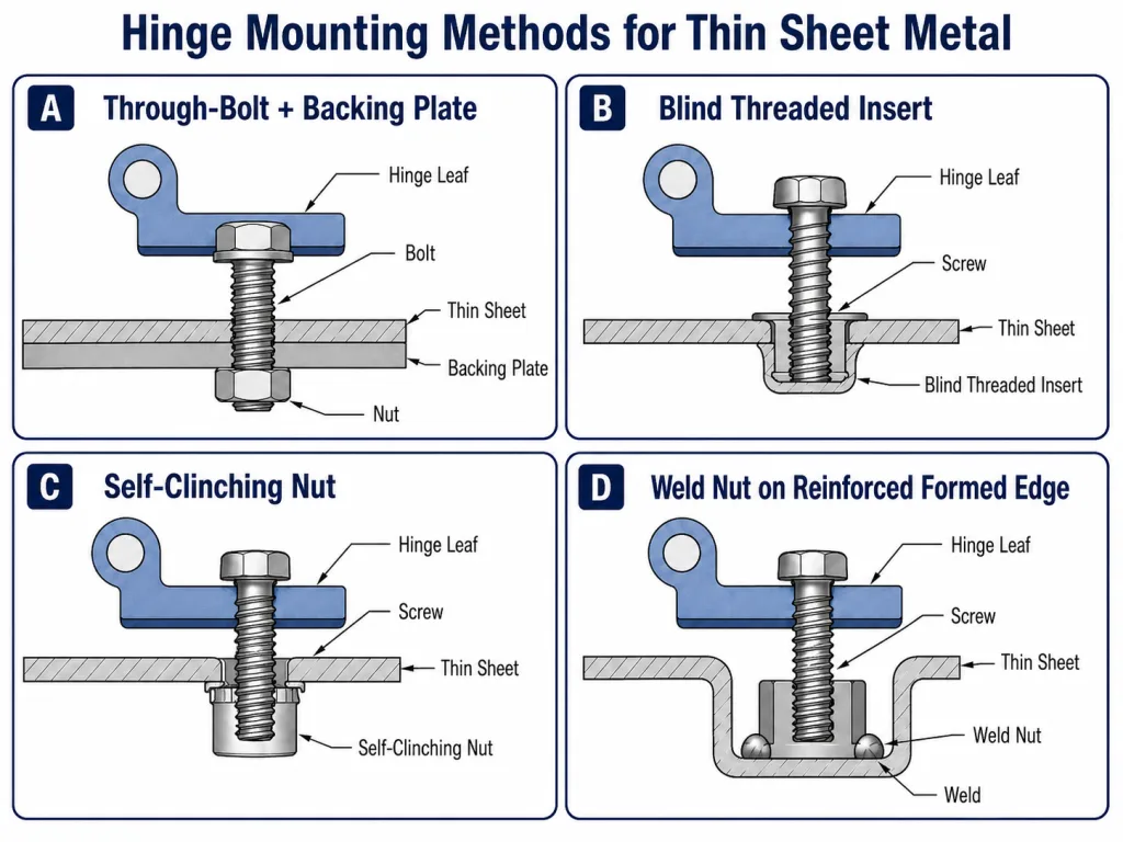
Quick engineering answer: Do not rely on a few threads cut directly into thin sheet for a loaded or frequently operated door. Use a joint that spreads load and provides stable thread engagement—commonly through-bolts with a backing plate, a correctly specified blind threaded insert, press-installed self-clinching hardware, or a reinforced welded mounting zone. The correct choice depends on load, rear access, production process, serviceability, and environment.
Start With the Door Load Path, Not the Fastener Type
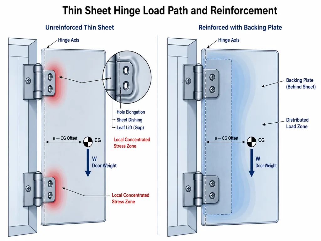
The mounting surface carries more than the door’s static weight. It also reacts the moment created by the distance from the hinge line to the door’s center of gravity, opening and closing forces, latch and gasket resistance, vibration, transport shock, and any impact at the mechanical stop. These forces pass through the hinge leaf, fasteners, inserts or nuts, reinforcement, sheet, and finally the surrounding frame.
First-pass relationship: M = W × e, where M is the moment applied to the mounting edge, W is the complete moving weight expressed as force, and e is the perpendicular distance from the hinge line to the assembly center of gravity. If the project begins with mass m, calculate W = m × g before using the relationship. This identifies the load entering the mounting joint; hinge count and spacing must be confirmed separately at the complete-door level.
A wide but light door can load the mounting edge more severely than a compact heavier door because the center of gravity is farther from the hinge line. A torque hinge can add another reaction because its resistance must be transmitted through the mounting ears every time the panel moves. A spring hinge adds return torque. A gasketed enclosure can add closing resistance and local frame deflection.
For heavy full-height enclosure doors, hinge count, vertical spacing, frame stiffness, and latch coordination need a broader system review. That calculation is covered in the heavy enclosure door hinge mounting guide; this page focuses on how the selected hinge is attached to thin sheet.
- Vertical shear: Door weight acts downward through the joint.
- Sagging moment: Door width and center-of-gravity offset create opposing reactions in the mounting joint and supporting structure.
- Leaf prying: A flexible hinge leaf or offset axis can pull the outer fastener row away from the sheet.
- Cyclic bearing: Repeated motion can elongate holes even when the first static test looks acceptable.
- Torque reaction: Friction, spring, gasket, cable, and latch forces pass back into the mounting structure.
- Impact load: Slamming or striking a stop can exceed the normal operating load for a short period.
Collect the Inputs That Control a Thin-Sheet Hinge Joint
Do not choose the insert or reinforcement from sheet thickness alone. Two panels made from the same gauge can require different joints because one has a formed return, the other is a flat skin, one has rear access, and the other is closed after assembly. Record the following information before releasing the mounting detail.
| Input | What to Confirm | Why It Changes the Joint |
|---|---|---|
| Complete moving assembly | Mass, dimensions, center of gravity, handles, windows, cables, insulation, and attached hardware | Defines shear, moment, operating force, and inertia |
| Door and frame material | Alloy or grade, thickness, temper or hardness, coating, and formed geometry | Controls bearing strength, clinching suitability, welding response, and corrosion compatibility |
| Hinge interface | Leaf size, hole pattern, countersinks, slots, axis offset, hinge count, and spacing | Controls local load distribution and alignment |
| Access behind the sheet | Open during assembly, permanently closed, or service-accessible | Determines whether through-bolts and backing plates are possible |
| Production sequence | Blanking, forming, welding, hardware insertion, coating, final assembly, and inspection | Determines when inserts or reinforcement can be installed without damaging finish |
| Service requirement | Hinge replacement, door removal, fastener access, adjustment, and field tools | Controls whether the joint should be removable or permanent |
| Operating duty | Cycle frequency, vibration, shock, stop impact, and required life | Controls fatigue, loosening, fretting, and hole wear risk |
| Environment | Indoor, outdoor, washdown, coastal, chemical, temperature, and electrical bonding needs | Controls materials, sealing, coating repair, and galvanic risk |
| Acceptance evidence | Allowed sag, gap, latch position, gasket compression, hole damage, and fastener movement | Defines what the installed sample must prove |
When a value is unknown, request the actual drawing, prototype measurement, or complete-door test. Do not replace missing mass, center of gravity, sheet hardness, insert grip range, or operating load with a generic catalog assumption.
Decide Whether the Sheet Can Carry the Joint Without Reinforcement
Thin sheet can support a hinge when the door is small, the load is low, the fastener pattern is wide, the sheet is formed into a stiff section, and the joint has adequate thread or clamp support. The same sheet can fail when it is a large flat panel with a narrow hinge footprint and repeated operation. The question is not “Is this gauge thick enough?” but “Can this mounting zone transfer the real load without permanent deformation or loss of clamp?”
Treat reinforcement as required when one or more of the following conditions are present:
- The flat sheet visibly flexes when the door is lifted at its free edge.
- The hinge leaf is narrower than the available load-spreading area.
- The door is wide, heavy, frequently operated, or subject to stop impact.
- A high-resistance torque or spring hinge transfers repeated reaction into a small footprint.
- The fastener would engage only shallow sheet threads.
- The joint must remain aligned with a latch, interlock, or gasket.
- The enclosure experiences vibration, transport shock, or repeated field removal.
- Existing holes are oval, cracked, pulled through, spun, or surrounded by fretting debris.
- The mounting zone is interrupted by a cutout, perforation, bend relief, seam, or sheet edge.
- The hinge is mounted to aluminum, soft sheet, or a finish that can creep under high local bearing pressure.
No universal thickness cutoff: Safe mounting depends on material, formed section, load, fastener geometry, hole quality, hinge spacing, cycle duty, and acceptance criteria. Use the hardware supplier’s permitted sheet range and test the real joint. A thickness number without those conditions is not an approval rule.
A formed flange, return, hem, channel, or box edge can be much stiffer than a flat sheet of the same thickness. Whenever possible, mount the hinge into a formed structural edge or add reinforcement that reaches one. Avoid making a small local patch carry the entire load if that patch is attached only to the same flexible skin.
For electrical cabinets where door construction, mounting space and access requirements must be considered together, compare the broader selection routes on our Electrical Enclosure Hinge Solutions page.
Choose a Mounting Method for Hinges on Thin Sheet Metal
Choose the joint architecture from rear access, production sequence, serviceability, and load. Use the three paths below for the first decision, then apply the detailed controls in the following subsections.
Rear Access Available
Use through-bolts with a backing plate when both sides remain accessible and the joint must be removable, inspectable, and capable of spreading load into a wider region.
One-Side Assembly Required
Use a correctly specified blind threaded insert when the rear side is closed and reusable screw threads are required. Confirm grip range, hole geometry, setting method, and anti-rotation performance.
Fabrication Can Be Redesigned
Use self-clinching hardware, weld nuts, or a formed reinforced edge when the attachment can be integrated before coating and final assembly.
Light-duty exception: Use direct tapping, thread-forming screws, or sheet-metal screws only for light, low-cycle, noncritical covers after validating the actual sheet and joint. Do not treat them as the default for a loaded door.
Through-Bolts and a Backing Plate
A through-bolted joint is usually the most transparent option when both sides are accessible. The backing plate spreads fastener reactions beyond the small rings around the holes and can bridge the hinge load into a bend, frame member, or wider panel region. The plate must be stiff enough to remain flat under bolt preload and door load; a thin decorative washer is not equivalent to structural backing.
Design the plate so it cannot rotate or become trapped in an inaccessible location during service. Confirm bolt-head and nut tool access, cable clearance, grounding points, and whether loose hardware can fall into electrical equipment. Captive nuts or a retained plate may improve assembly control.
Blind Threaded Inserts
Blind threaded inserts create reusable threads from one side. They are useful in closed cabinets and modular assemblies, but their performance depends on the exact insert, grip range, hole size, installation setting, sheet material, and load direction. A loose installation can spin during screw tightening; an over-set insert can distort the sheet or damage the internal thread.
Do not approve a blind insert by thread size alone. Specify the body style, head style, material, grip range, hole tolerance, anti-rotation feature, setting method, and required pull-out and torque-out performance in the actual sheet. For demanding hinges, place the inserts through a thicker reinforcement strip rather than directly into a broad flexible skin.
Self-Clinching Nuts and Studs
Self-clinching hardware is press-installed into a prepared hole so surrounding sheet flows into the fastener undercut. It can provide a clean, repeatable production joint, but only when the selected hardware is compatible with sheet thickness and hardness and is installed with controlled parallel force. It should not be hammered into place or treated as a generic replacement for every rivet nut.
Place the hardware far enough from bends, edges, and adjacent features for the sheet to flow correctly. Confirm whether installation occurs before or after forming and coating. A clinching operation that marks a cosmetic face or cracks a brittle finish may be unacceptable even when the fastener is mechanically secure.
Weld Nuts, Studs, and Local Reinforcement
Welded hardware can move the thread into a stronger component and eliminate loose rear nuts, but thin sheet is sensitive to heat distortion. Use a fixture that controls the hinge mounting plane, define the weld sequence, and inspect the final hole pattern and flatness after cooling. Repair or reapply the protective finish around welds as required by the project.
Welding directly beside an installed hinge can damage bushings, lubricant, springs, polymer friction elements, or plating. Weld the mounting hardware or reinforcement before the hinge is installed unless the approved process explicitly protects the hinge.
Design Reinforcement That Transfers Load Beyond the Hinge Footprint
A reinforcement plate should do more than thicken the immediate hole. It should spread load into a larger panel area, formed edge, frame member, or structural return. A short plate that ends directly beside the last fastener can move the stress concentration rather than remove it.
- Width and length: Extend beyond the hinge footprint and fastener rows so bearing and bending are distributed.
- Stiffness: Select thickness, bends, ribs, or attachment points that prevent the reinforcement from peeling away with the hinge leaf.
- Connection to the structure: Weld, rivet, clinch, bolt, or form the reinforcement so load reaches sound material rather than remaining in the same flexible sheet.
- Flat mounting plane: Prevent weld beads, clinch heads, coatings, seams, or embossments from rocking the hinge leaf.
- Drainage and crevices: Avoid pockets that trap water or cleaning solution behind the plate.
- Electrical and corrosion compatibility: Control dissimilar-metal contact, coating damage, and any bonding path.
- Service access: Make screws, nuts, adjusters, and removable-door features reachable without dismantling unrelated equipment.
For a cabinet edge, a formed return or internal angle often gives a better load path than a flat backing strip. For a lid, a channel or boxed edge can keep the hinge axis stable. For a torque hinge, reinforce both the moving and stationary sides because the mounting ears see reaction every time the panel is repositioned.
Reinforce the weak side: A rigid frame leaf attached to a flexible door skin still allows sag. Review both leaves, both substrates, all fasteners, and the structure behind them.
Locate the Hinge Axis and Hole Pattern From Stable Datums
Accurate holes in the wrong coordinate system still create a misaligned door. Locate the hinge axis from stable formed edges, frame datums, or controlled assembly surfaces—not from a free sheet edge that moves after forming or welding. The door and frame drawings must use the same axis definition.
Read hole diameter, center spacing, slots, countersinks, thread callouts, edge distance, and pattern position together. The broader document-control method is covered in the guide to the hinge spec sheet and engineering drawing.
- Dimension the hinge pattern from the axis or a controlled mounting datum.
- Avoid chained dimensions when accumulated variation can shift the final hinge.
- Keep holes clear of bend radii, relief cuts, seams, perforations, and weak sheet edges.
- Use slots only in the direction where adjustment is needed; do not let every hinge float in every direction.
- Confirm fastener heads, washers, nuts, and installation tools fit the available envelope.
- Check the moving door edge, hinge barrel, pin head, and leaf against the full opening range.
- For removable hinges, preserve the required lift or separation vector and anti-lift hardware access.
- Account for coating buildup and whether dimensions apply before or after finish.
Countersunk screws can locate a hinge leaf but can also wedge the leaf and thin sheet out of flatness. Use them only when the countersink geometry, leaf thickness, substrate support, and screw head are controlled. A clearance hole with a flat-bearing head may be more forgiving when adjustment or thin-sheet support is required.
Prepare Holes and Mounting Surfaces Without Weakening the Sheet
Hole quality affects bearing, insert retention, fastener preload, corrosion, and alignment. A punched hole with heavy burr, a drilled hole with taper, or a laser-cut hole with damaged coating can change how the insert seats and how the hinge leaf lies against the panel.
- Confirm the released pattern. Verify revision, hinge handing, door/frame leaf assignment, and the intended installation side.
- Produce the holes by the approved process. Control punch clearance, drill size, laser condition, or machining so the hole meets the insert or fastener specification.
- Deburr without rounding away support. Remove sharp burrs and loose material while preserving the required hole diameter and flat bearing surface.
- Inspect local flatness. Correct distortion, raised edges, weld spatter, clinch marks, or coating lumps that would rock the hinge leaf.
- Install captive hardware at the planned production stage. Press, set, or weld hardware before the operation that would block access.
- Restore finish where required. Protect bare cut edges, drilled holes, and welded areas according to the project coating system.
- Keep friction surfaces clean. Do not allow sealant, paint, abrasive debris, or metal chips into the hinge knuckle, bearing, spring, or torque mechanism.
Do not enlarge a mislocated hole until the door fits. That may solve assembly once while leaving inadequate bearing area and uncontrolled position. Correct the fixture, datum, pattern, or reinforcement, then document any approved slot or oversize-hole strategy.
Align Multiple Hinges Before Final Tightening
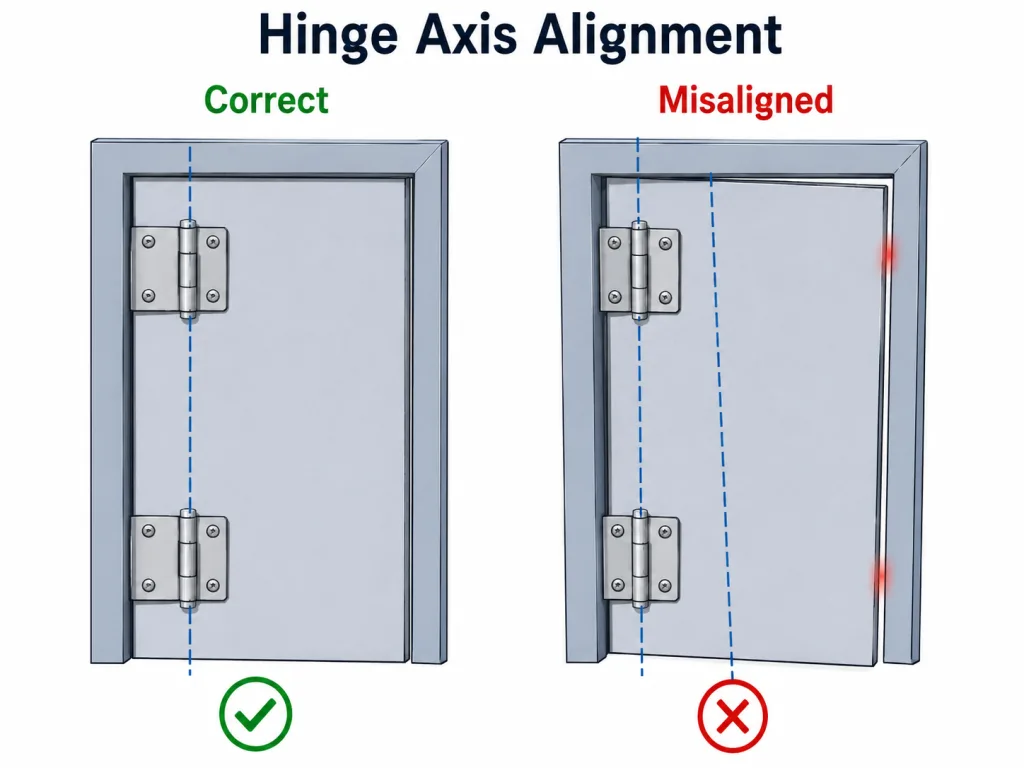
Two or more hinges must share one practical rotation axis. Thin panels can flex enough to hide misalignment during assembly, then spring back and force the hinge pins sideways after tightening. The result may be binding, high operating force, uneven load sharing, insert movement, or rapid wear.
- Support the complete door at its intended position. Do not use loose hinges to carry the door while the pattern is being established.
- Establish the frame-side axis. Use a fixture, straight reference pin, laser, or controlled datum appropriate to the production process.
- Install all hinge fasteners finger-tight. Preserve the intended adjustment direction without allowing the leaves to rock.
- Fit the door-side leaves. Maintain the design gap, offset, and gasket relationship.
- Cycle the door slowly. Check for binding, leaf movement, frame twist, cable pull, and stop interference.
- Tighten gradually. Alternate between hinges and fastener rows so one leaf does not pull the others out of line.
- Recheck after full tightening. Confirm the axis, door gap, latch position, gasket compression, and operating force.
- Record shims or adjustments. Production should not depend on undocumented operator judgment.
A removable lift-off door also requires aligned pin direction and disengagement travel. The dedicated lift-off hinge clearance and alignment guide covers those type-specific requirements; do not expand them into this general mounting instruction.
Tighten the Joint Without Crushing Sheet or Spinning Inserts
Fastener torque is not a universal value determined only by screw diameter. The usable setting depends on bolt material, coating, lubrication, nut or insert design, sheet support, joint stack, washers, thread engagement, and required clamp. Excessive torque can dish the sheet, collapse a spacer, spin a blind insert, strip shallow threads, or distort the hinge leaf. Too little clamp can allow fretting and hole elongation.
- Use the fastener or insert supplier’s approved installation and tightening data for the exact materials and finish.
- Support thin sheet with a backing plate, spacer, embossment, or formed section where clamp load would otherwise crush it.
- Use washers or flange heads only when their bearing area and clearance fit the hinge leaf and reinforcement.
- Keep screws long enough for full intended engagement without bottoming in a closed insert.
- Control threadlocker, prevailing-torque nuts, or other retention features as part of the joint specification.
- Do not use a spinning insert as a reason to apply more torque; replace it and correct the hole or setting process.
- Mark or electronically record critical fastening operations when production consistency is required.
- Recheck the joint after the first loaded cycles if settling of coatings, gaskets, or soft layers is possible.
Installation acceptance: After tightening, the hinge leaf must remain flat, the sheet must show no permanent dish or cracking, inserts must not rotate, and the door must move without new binding. A torque wrench reading alone does not prove the joint is sound.
Protect Sealing, Corrosion Resistance, and Electrical Bonding
A hinge joint can compromise an enclosure even when it remains mechanically secure. Fastener holes can create leakage paths, damaged coatings can initiate corrosion, backing plates can trap moisture, and insulating finishes can interrupt a required bonding path. These issues must be resolved in the complete assembly rather than assumed from the hinge material.
- Sealing: Define whether the joint needs sealing washers, thread sealant, a closed-end insert, a gasketed reinforcement, or a sealed internal enclosure wall.
- Coating: State how bare holes, cut edges, welds, and damaged finish are repaired.
- Galvanic compatibility: Review hinge, fastener, insert, backing plate, and cabinet materials together.
- Drainage: Avoid horizontal pockets and crevices that retain water or cleaning chemicals.
- Bonding: If the door requires electrical continuity, use a defined bonding feature rather than assuming hinge contact through painted leaves and lubricated pins.
- Service: Make sure replacement does not destroy the sealing or coating strategy.
This page does not assign an ingress-protection classification or corrosion-test duration. Those are project-specific enclosure requirements. The mounting detail must simply preserve the sealing and material strategy that the complete enclosure is designed and tested to achieve.
Use the Failure Evidence to Correct the Mounting Joint
| Observed Evidence | Likely Mounting Problem | Corrective Direction |
|---|---|---|
| Holes become oval in the direction of door sag | Insufficient bearing area, clamp loss, or flexible substrate | Add reinforcement, improve clamp, widen load distribution, and verify hinge spacing |
| Blind insert rotates during service | Incorrect hole, grip range, body style, or setting | Replace the insert and correct the specified installation process |
| Sheet dishes under the hinge leaf | Excessive clamp, narrow bearing area, or unsupported sheet | Add backing support or spacer and revise tightening control |
| Cracks begin at a fastener hole or sheet edge | Low edge distance, cyclic prying, burr, or local stress concentration | Relocate pattern, improve hole quality, and extend reinforcement |
| Door binds after final tightening | Hinge axes are not coaxial or leaves are pulled onto uneven surfaces | Correct datums, flatness, shimming, and tightening sequence |
| Latch or gasket alignment changes over time | Mounting zone flexes or fasteners settle | Stiffen both substrates and validate the complete load path |
| Fretting dust or polished rings appear under the leaf | Micro-movement from inadequate clamp or surface compliance | Restore joint preload and structural support after inspecting damage |
| Welded area pulls the hinge out of plane | Heat distortion or uncontrolled weld sequence | Re-fixture, revise weld sequence, and inspect after cooling |
| Corrosion begins behind a plate or around holes | Trapped moisture, coating damage, or incompatible metals | Improve drainage, sealing, material pairing, and finish repair |
Do not correct every symptom by increasing fastener size or selecting a stronger hinge. Identify whether the failure is thread pull-out, sheet bearing, plate bending, joint slip, misalignment, welding distortion, or environmental attack. Each mechanism needs a different correction.
Validate the Thin-Sheet Mounting Joint on the Complete Assembly
A hinge mounted successfully on an unloaded coupon has not yet proven the mounting joint. Validate the production-intent hinge, fasteners, inserts, reinforcement, sheet material, finish, and installation process on the complete assembly, but keep the acceptance criteria focused on the local joint.
| Validation Check | What to Measure or Inspect | Acceptance Basis |
|---|---|---|
| Leaf seating | Leaf flatness, rocking, local gaps, and contact after tightening | Released joint drawing and approved sample |
| Sheet deformation | Permanent dish, pull-through, cracking, or local bending under the specified load | Project mounting-joint limit |
| Insert and fastener stability | Insert rotation, pull-out, loosening, preload loss, or visible movement | Fastener or insert specification and quality plan |
| Cyclic joint condition | Fretting, hole elongation, screw movement, or reinforcement separation after the specified cycles | Project duty and sample-approval plan |
| Local finish and sealing | Coating damage, corrosion initiation, exposed edges, or a leakage path around the mounting zone | Released finish and local sealing detail |
Complete-door sag, latch alignment, gasket compression, operating force, and service clearance must be approved at the assembly level. This page does not redefine those system acceptance limits.
Mark the initial fastener position where useful, photograph the mounting zone, and retain the sheet and hardware identification with the test record. If the design uses blind inserts or press-installed hardware, include the installation tool, setting, and inspection method in the production reference.
A preliminary recommendation can identify the likely mounting architecture. Engineering review confirms the drawing and load path. Sample approval confirms the production-intent assembly. Production approval requires the released joint specification and repeatable process. These states are distinct, but they do not need a separate project-stage framework in this article.
Thin Sheet-Metal Hinge Mounting Checklist
Door and Load
- ☐ Complete moving mass and center-of-gravity location are known.
- ☐ The complete-door load case has been approved.
- ☐ The approved hinge count and spacing have been received from the complete-door design.
- ☐ Hinge torque, spring, gasket, cable, latch, and stop reactions that enter the mounting joint are identified.
- ☐ Vibration, shock, cycle duty, and service handling are defined.
Sheet and Reinforcement
- ☐ Door and frame material grade, thickness, hardness, and finish are known.
- ☐ Both hinge leaves have adequate structural support.
- ☐ Reinforcement transfers load beyond the hinge footprint.
- ☐ Cutouts, bends, seams, perforations, and sheet edges have been checked.
- ☐ The mounting plane is flat and free from weld beads, clinch marks, and coating lumps.
Attachment Hardware
- ☐ Rear access and service access are confirmed.
- ☐ The mounting method is defined: through-bolt, blind insert, self-clinching hardware, welded hardware, or formed reinforcement.
- ☐ Fastener or insert part number, material, grip range, and installation method are defined.
- ☐ Bolt length, thread engagement, bearing area, and retention method are correct.
- ☐ Installation data comes from the exact fastener or insert supplier specification.
Holes and Alignment
- ☐ The pattern is located from stable datums and the hinge axis.
- ☐ Hole size, tolerance, edge condition, and burr removal are controlled.
- ☐ Multiple hinge axes are aligned before final tightening.
- ☐ Slots, shims, or adjustment features are documented.
- ☐ The hinge leaf remains flat after tightening.
Installed Joint Validation
- ☐ The mounting joint shows no permanent deformation under the specified load.
- ☐ Inserts and fasteners remain stable after the specified cycles.
- ☐ Hole edges show no elongation, cracking, pull-through, or fretting.
- ☐ Local coating and sealing details remain intact.
- ☐ The production-intent sample matches the released mounting drawing and process.
Frequently Asked Questions
Can I tap threads directly into thin sheet metal for a hinge?
Only for light, low-cycle, noncritical applications after the real joint is validated. Loaded or frequently operated doors usually need more stable thread engagement through a backing plate, blind threaded insert, self-clinching hardware, weld nut, or reinforced formed section.
Is a rivet nut enough for mounting an industrial hinge?
It can be, but not automatically. The insert must match the sheet material, thickness, grip range, hole, installation setting, and load direction. High prying or cyclic loads may require the insert to pass through a reinforcement plate rather than the flexible sheet alone.
When should I use a backing plate?
Use a backing plate when rear access is available and the sheet needs a wider, stiffer bearing area. It is especially useful for wide or heavy doors, narrow hinge footprints, repeated operation, existing hole damage, or joints where alignment must remain stable.
Can self-drilling or sheet-metal screws mount a hinge?
They may suit light access covers with low duty and no safety or alignment function. They are a poor default for loaded doors, high-cycle access, torque hinges, vibration, repeated service, or shallow sheet that cannot retain the thread.
Should hinge hardware be installed before or after coating?
The sequence depends on the hardware and finish. Press-installed and welded hardware is commonly integrated during fabrication, but coating buildup, masking, heat damage, cosmetic marking, and corrosion repair must be planned. Follow the released process for the exact hardware and finish.
Mount the Hinge as Part of the Sheet-Metal Structure
The reliable way to approach how to mount hinges on thin sheet metal is to design the hinge, fasteners, reinforcement, sheet, and frame as one load path. Begin with the complete door moment and duty. Decide whether the sheet can carry the joint. Then choose through-bolts, blind threaded inserts, self-clinching hardware, welded hardware, or a formed reinforced edge according to access, production, service, and load.
Control the hole pattern from stable datums, keep multiple hinge axes aligned, tighten without crushing the sheet, and protect the coating, seal, drainage, and bonding strategy. Final approval belongs to the production-intent mounting joint on the complete assembly—not an unloaded hinge or generic fastener coupon.
Need a Thin-Sheet Hinge Mounting Review?
Send the door drawing, complete moving mass, center-of-gravity location, sheet material and thickness, hinge pattern, rear access, operating duty, and mounting-zone photos to send your mounting drawing.