-
+86 13720060320
-
lanna@haitangs.com

Detent Hinge vs Torque Hinge | Fixed, Free-Stop or Hybrid
The detent hinge vs torque hinge decision is often described as “fixed positions versus hold at any angle.” That is useful as a first screen, but it is not always technically complete. Some detent hinges only index the panel at selected angles. Some free-stop torque hinges resist movement throughout the working range without an index. Other products combine both functions: friction-based holding between positions plus a stronger mechanical engagement at selected angles.
The correct engineering question is therefore not simply “detent or torque?” It is: what must the panel do at the selected positions, between those positions, and at the end of travel? Those three conditions determine whether the application needs indexed-only behavior, free-stop behavior, or a hybrid detent-and-friction mechanism.
This article begins before model selection and ends once the positioning architecture and acceptance fields are defined. The general definition of torque hinges and their broader product families remains in our guide to what a torque hinge is.
Content boundary: This page does not list available detent models, calculate the final torque value, compare factory-set with field-adjustable torque, or establish a full life-test procedure. Those are separate search tasks assigned to separate URLs.
Detent Hinge vs Torque Hinge Is Not Always a Binary Choice
| Positioning Architecture | Behavior at Selected Positions | Behavior Between Positions | Use It When |
|---|---|---|---|
| Indexed-only detent | Mechanism enters one or more defined positions and resists release | Low, variable, spring-influenced, or otherwise model-specific; do not assume the panel will hold | The task requires repeatable angles and intermediate holding is not needed |
| Free-stop torque | No positive index is required; the user creates the position | Friction resists motion throughout the specified working range | Different users or service tasks require many possible angles |
| Hybrid detent + friction | Selected angles have a stronger engagement or clear tactile confirmation | The panel also receives defined friction support away from the indexed positions | The task needs repeatable angles and useful support between them |
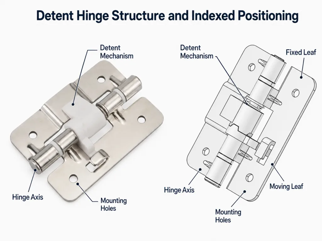
This three-way separation is important because the word detent describes an indexed engagement feature, while torque describes resistance to rotation. A product can contain one function or both. The supplier drawing and test data must state which behavior the exact model provides.
Do not use “positioning hinge” as the complete specification. It can refer to several different mechanisms and does not define whether the panel holds between indexed positions.
Define the Motion States the User Actually Needs
Write the panel motion as a sequence before discussing hinge construction. This prevents a familiar problem: selecting a mechanism that performs well at one angle but fails during the rest of the user task.
- Closed state: Decide whether closure is controlled by a latch, seal, detent, friction, magnet, or separate hardware.
- Release from closed: Define whether the user should feel a click, a smooth breakaway, or almost free movement.
- Travel to the first working position: State whether the panel may swing freely, must remain supported, or must stop wherever released.
- Working positions: Identify whether the task uses a small number of repeatable angles or a wide range of user-selected angles.
- Movement between working positions: Define the acceptable resistance and whether temporary intermediate holding is required.
- Maximum opening: Separate the final useful position from the structural overtravel stop.
- Return path: Confirm whether the same engagement and operating effort are required in the opposite direction.
A maintenance cover with closed, inspection, and fully open positions may suit indexed behavior. A display that each operator adjusts for viewing height usually needs free-stop positioning. A diagnostic lid that must click at a calibration angle but also remain supported while moving may need a hybrid mechanism.
Compare Torque-Angle Behavior, Not Just Product Names
The clearest technical comparison is the resistance profile through the opening angle. No numeric curve should be assumed without model-specific test data, but the qualitative behavior can still be defined.
Indexed Detent Region
As the hinge approaches a detent, the internal geometry may guide the mechanism toward the indexed position. At the position, resistance to leaving the detent rises. The peak effort needed to move out is the release threshold. The angular window, approach direction, backlash, structural compliance, and wear determine how repeatably the assembled panel returns to the intended angle.
Free-Stop Region
A free-stop torque hinge provides resisting torque across the working range. The panel stays where released only when the available hinge torque exceeds the actual external moment at that position. Breakaway behavior and running resistance may differ, so a panel can hold correctly yet still feel jerky or excessively stiff during movement.
Hybrid Region
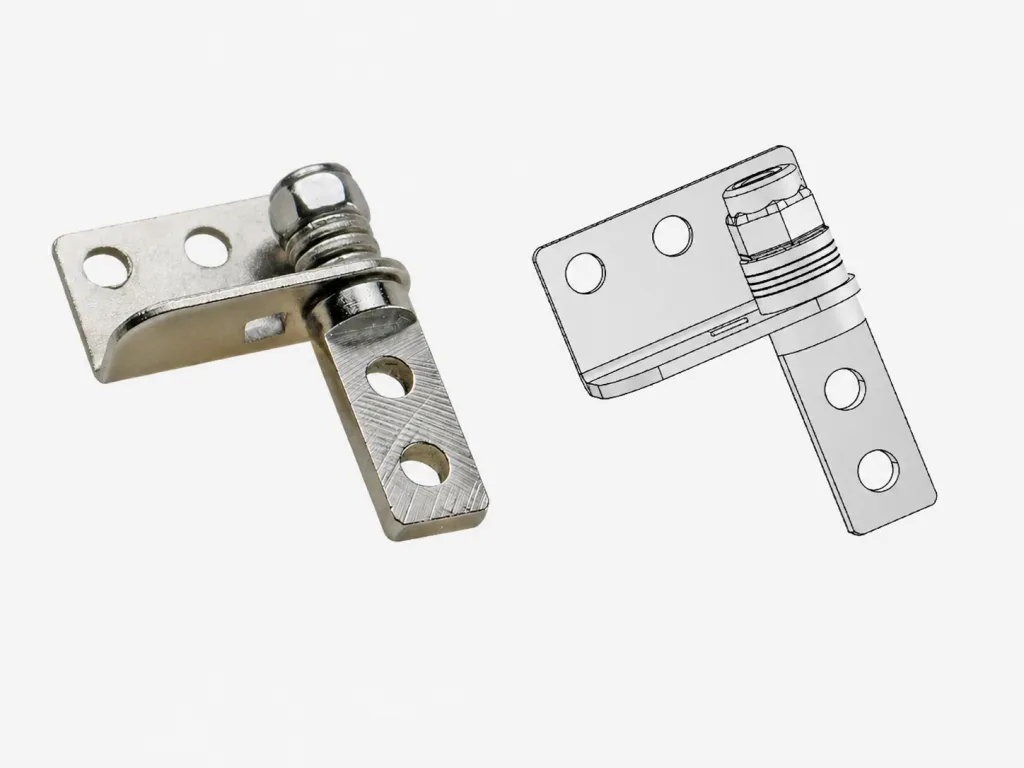
A hybrid design has a friction baseline through the working range and a distinct engagement feature at selected angles. The specification must separate the baseline holding requirement from the added engagement and release behavior. One number labeled “torque” cannot describe both functions.
Model availability, detent angles, dimensions, and product-specific ratings belong on the detent positioning hinge models page. This comparison page only defines which behavior the application requires.
Keep Position Accuracy, Holding, Release, and Stop Load Separate
| Function | Question to Answer | Common Wrong Assumption |
|---|---|---|
| Position accuracy | How close must the assembled panel return to the intended angle, and from which approach direction? | A nominal detent angle automatically equals the final panel angle |
| Holding at position | What external panel moment must be resisted while fully engaged or held by friction? | A noticeable click proves adequate load capacity |
| Release behavior | What effort should move the panel out of the position, and where does the user apply that effort? | Release torque and holding capacity are the same value |
| Between-position holding | Must the panel stay at intermediate angles, and under which load and orientation? | Every detent hinge supports the panel between clicks |
| End-stop load | Which structure absorbs repeated overtravel or impact at maximum opening? | The detent or friction mechanism is automatically a structural stop |
These functions can be provided by one mechanism or divided among the hinge, a frame-mounted stop, a latch, and another support feature. Treating them as separate requirements prevents a detent from being overloaded as a stop and prevents a torque hinge from being blamed for angle repeatability it was never designed to provide.
If free-stop behavior is selected, calculate the required holding torque on the dedicated torque hinge calculator. This page deliberately does not repeat the sizing formula or safety-factor examples.
Decide What Must Happen Between Indexed Positions
Between-position behavior is the most frequently omitted field in a detent requirement. Two hinges can share the same nominal detent angles but behave very differently while traveling between them.
| Required Intermediate Behavior | Likely Architecture | Critical Verification |
|---|---|---|
| Panel may move with low resistance and does not need support | Indexed-only detent may be suitable | Confirm the panel cannot fall, slam, or overload cables during travel |
| Panel should remain supported at temporary angles | Hybrid detent + friction | Verify baseline holding away from the detent windows |
| User needs unrestricted choice of working angle | Free-stop torque | Verify holding and user effort throughout the working range |
| Panel must return only to repeatable programmed positions | Indexed-only or hybrid detent | Verify angle tolerance, approach direction, and release effort |
| Selected positions require a clear click, but other angles are occasionally used | Hybrid architecture | Define both detent engagement and between-position holding |
Do not add many detents merely to imitate free-stop positioning. Closely spaced indexes can create an uneven user feel, increase wear events, and still fail to provide the exact angle a user wants. Likewise, do not rely on friction alone when the task requires a repeatable calibration, inspection, or service angle.
Translate User Feel Into Measurable Requirements
Words such as “smooth,” “firm,” “positive,” and “easy” are useful design goals but weak production criteria. Convert them into observable or measurable conditions.
| User Statement | Engineering Field to Define | Why It Matters |
|---|---|---|
| “I need a clear click.” | Engagement event, approach direction, and acceptable tactile or audible feedback | Separates a weak index from an intentional confirmation |
| “It must not move accidentally.” | Holding condition at the indexed position or throughout the free-stop range | Defines the external disturbance the mechanism must resist |
| “It should be easy to open.” | Release or breakaway effort measured from the real hand location | Hand distance from the axis changes perceived effort |
| “It must feel smooth.” | Running resistance, stick-slip limit, and allowed change by angle | Prevents a hinge that holds but moves poorly |
| “Every unit must feel the same.” | Production tolerance and measurement condition | Prevents acceptance by subjective operator feel alone |
Specify the user’s hand location, handle length, gloves, operating frequency, panel inertia, and nearby hazards. A release event that feels acceptable on a loose hinge can make a large panel jump when the full assembly stores energy in the seal, cable, or flexible bracket.
Use Load and Orientation as an Architecture Gate
Load does not decide the positioning architecture by itself, but it can eliminate an otherwise attractive option. A horizontally hinged lid experiences a gravity moment that changes by angle. A vertical-axis panel may have little gravity demand but still receive cable force, seal force, vibration, slope, wind, or operator impact.
- For indexed-only detents: confirm that the engaged position can carry the actual panel moment and that travel between positions remains safe.
- For free-stop torque: confirm that available resistance covers the highest external moment through the required range without creating excessive operating effort.
- For hybrid designs: define a baseline friction requirement away from the detents and a separate engaged-position requirement.
- For all three: provide a structural stop where repeated end-of-travel impact is foreseeable.
A detent that provides excellent tactile feedback may have limited load-holding capacity. A high-torque hinge may support the load but be unsuitable when the operator must return to one exact service angle. The mechanism must satisfy both motion behavior and load behavior.
Choose the Multi-Hinge Architecture Without Creating Binding
Using two positioning hinges introduces synchronization requirements that do not exist in a single-hinge sample. The correct arrangement depends on which function each hinge supplies.
| Arrangement | Potential Advantage | Primary Risk |
|---|---|---|
| Two detent hinges | Shared structural support and engagement at both ends | One hinge indexes first because of angle, mounting, or frame tolerance |
| One detent hinge + one follower/support hinge | Only one mechanism defines the index | The follower must not add friction or geometry that prevents engagement |
| Two free-stop torque hinges | Shared holding torque and improved panel support | Unequal torque or non-coaxial axes create twist and uneven wear |
| Two hybrid hinges | Shared holding plus indexed feedback | Both friction and detent timing must be matched |
| One detent hinge + one torque hinge | Can provide index plus between-position support | The torque hinge may resist full detent engagement or change release feel |
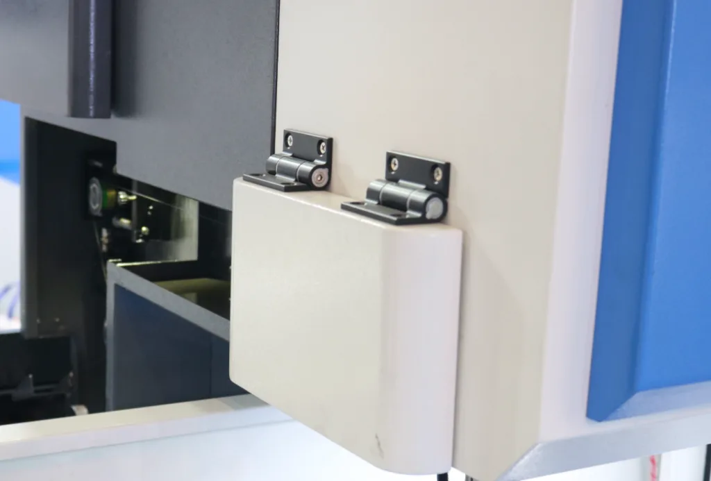
A mixed arrangement is not automatically wrong, but it must be treated as a system rather than two independent catalog parts. Confirm the common axis, mounting datums, frame stiffness, load sharing, engagement timing, and movement in both directions on the complete panel.
Do not tune around misalignment: Increasing friction to hide poor detent synchronization may make the panel appear stable during a short test while raising release effort, bracket stress, and wear.
Recognize When the Application Really Needs a Hybrid Mechanism
A hybrid requirement is real when both of the following are necessary: the user needs positive confirmation at selected angles, and the panel must also remain supported at useful intermediate angles. Do not specify a hybrid merely because it sounds more capable; extra functions add force interactions, tolerances, wear points, and validation work.
Before requesting a hybrid design, answer four questions:
- Which angles require a defined engagement?
- What holding behavior is required outside those engagement windows?
- How much additional release effort is acceptable at the indexed angles?
- Should the user feel the same baseline resistance before and after each detent?
Once free-stop behavior has been chosen, the next decision—factory-set resistance or field adjustment—belongs to the constant vs adjustable torque hinge guide. It should not be mixed into the detent-versus-free-stop architecture decision.
Write a Positioning Requirement Before Selecting a Model
The specification should describe behavior rather than starting with a supplier part number. The examples below show the minimum structure; all values remain project-specific or supplier-confirmed.
| Architecture | Required Fields |
|---|---|
| Indexed-only detent | Reference datum; nominal positions θ1, θ2, θ3; angular tolerance; approach direction; engaged holding condition; release threshold; between-position behavior; stop function; cycle condition |
| Free-stop torque | Working range; required hold positions; opening and closing direction; breakaway and running resistance; measurement angle, speed, and temperature; allowed drift; post-cycle retention |
| Hybrid detent + friction | All free-stop fields plus detent positions, engagement window, added release behavior at each index, and baseline holding requirement outside the detents |
Incomplete: “Provide a three-position hinge that holds the cover.”
Improved: “The cover requires indexed positions at project-defined angles θ1, θ2, and θ3. The assembled angle tolerance, approach direction, engaged holding condition, release threshold, and behavior between indexes are Project-Specific. Maximum-opening impact is carried by a separate frame stop. Supplier Confirmation Required for the proposed mechanism and test method.”
Do not copy angle values, load capacities, or release forces from another product. The selected model drawing, test report, and approved sample must describe the same revision.
Failure Modes That Expose the Wrong Positioning Architecture
| Field Symptom | Likely Architecture Error | What to Review |
|---|---|---|
| User repeatedly searches for the same angle | Free-stop was selected where a repeatable index was needed | Add an indexed position or another angle-reference feature |
| User wants positions between the available clicks | Indexed-only architecture is too restrictive | Evaluate free-stop or hybrid behavior |
| Panel falls or accelerates between detents | Between-position holding was never defined | Confirm travel safety and baseline support |
| Panel will not settle fully into the detent | Added friction, cable load, seal force, or hinge mismatch blocks engagement | Measure the complete system near the engagement window |
| Panel jumps when released from the detent | Release threshold, hand location, inertia, or stored structural energy is excessive | Review user force and assembly compliance |
| Panel holds but does not return to an exact angle | Free-stop behavior was mistaken for mechanical indexing | Use a detent or separate locator |
| Two detents engage at different times | Mounting and angle tolerance are not synchronized | Review datums, axes, frame twist, and hinge pairing |
| Behavior changes rapidly after cycling | Detent wear, friction wear, preload shift, or mounting movement | Define post-cycle angle, release, and holding acceptance |
These symptoms should be traced back to the motion requirement. Replacing the hinge with a “stronger” part does not correct a missing index, undefined intermediate behavior, or an overloaded end stop.
Detent Hinge vs Torque Hinge Decision Workflow
- List the required panel states from closed through maximum opening (see “Define the Motion States”).
- Choose indexed-only, free-stop, or hybrid behavior based on what must happen at and between working positions (see “Not Always a Binary Choice”).
- Separate angle accuracy, holding, release, intermediate support, and stop load so one mechanism is not assigned an undefined job.
- Define user feel as measurable behavior, including hand location and movement in both directions.
- Use load and orientation as a gate without turning this comparison into the torque-sizing page.
- Select the single- or multi-hinge architecture and verify synchronization, common axis, and frame stiffness.
- Write the mechanism-specific requirement before comparing supplier models.
- Validate the complete production-intent assembly and recheck the correct outputs after the project-defined cycles and conditions.
Composite Engineering Scenario: Instrument Calibration Cover
Engineering example: This is a composite engineering scenario created to explain the selection logic. It is not a customer project record or product test claim.
An instrument has a hinged calibration cover. The initial request says the cover should “click open and stay anywhere.” The phrase combines two different functions, so the team separates the task.
Technicians need one repeatable calibration angle because the internal reference target must remain visible. They also sometimes pause the cover at intermediate angles while routing a probe cable. At maximum opening, the cover may be bumped during service.
An indexed-only detent provides the repeatable calibration angle but does not automatically prove that intermediate positions are supported. A free-stop torque hinge supports intermediate positions but does not mechanically return the cover to the calibration angle. The requirement therefore becomes hybrid: defined baseline holding through the working range plus a stronger engagement at the calibration position.
The team assigns maximum-opening impact to a frame stop rather than the positioning mechanism. It then defines the calibration-angle tolerance, approach direction, baseline holding condition, detent release behavior, cable load, and post-cycle acceptance. The supplier model is selected only after those outputs are agreed.
This scenario does not prove that every calibration cover needs a hybrid hinge. It shows why the behavior at the selected angle, between angles, and at end of travel must be separated before choosing the product.
Validate the Chosen Positioning Behavior on the Complete Assembly
| Validation Check | Indexed-Only Detent | Free-Stop Torque | Hybrid |
|---|---|---|---|
| Selected positions | Verify assembled angle and engagement from each required approach direction | Confirm the user can place the panel at all required working angles | Verify both indexed angles and non-indexed working angles |
| Between positions | Confirm travel is safe and matches the stated low-resistance or unsupported condition | Verify holding and movement quality throughout the required range | Verify baseline holding outside detent windows |
| User effort | Measure engagement and release behavior from the real hand location | Check breakaway and running effort in both directions | Check baseline effort plus added detent release |
| Multiple hinges | Confirm simultaneous engagement or intentional follower behavior | Confirm matched resistance and no panel twist | Confirm both torque sharing and detent timing |
| End of travel | Confirm a separate stop where impact is expected | Confirm a separate stop where impact is expected | Confirm a separate stop where impact is expected |
| After conditioning | Recheck angle, release, play, and engagement | Recheck holding, drift, and movement quality | Recheck both sets of outputs |
A loose hinge sample can demonstrate the mechanism, but it cannot approve the installed behavior. Use the production-intent panel, frame, fasteners, cable harness, seal, handle location, stop, and orientation.
A preliminary recommendation identifies a likely architecture. Engineering review requires actual load and geometry. Sample approval applies to the tested configuration. Production approval must not be inferred after changes to the panel, hinge revision, detent geometry, friction setting, bracket, cable route, or stop.
Positioning-Architecture Checklist
DETENT, FREE-STOP, OR HYBRID POSITIONING REVIEW
---------------------------------------------------
MOTION ARCHITECTURE
[ ] Closed, working, intermediate, and maximum-open states defined
[ ] Indexed-only, free-stop, or hybrid behavior selected
[ ] Behavior between indexed positions explicitly stated
[ ] Maximum-opening stop function separated from positioning

INDEXED-POSITION REQUIREMENTS
[ ] Nominal positions referenced from a clear datum
[ ] Angular tolerance and approach direction stated
[ ] Engaged holding condition defined
[ ] Engagement and release behavior defined
[ ] Backlash or allowable movement at the index defined where relevant

FREE-STOP REQUIREMENTS
[ ] Working range and required hold positions defined
[ ] Complete moving load and center of gravity confirmed
[ ] Opening and closing behavior defined separately
[ ] Breakaway, running, and drift conditions stated
[ ] Measurement angle, speed, and temperature stated

HYBRID REQUIREMENTS
[ ] Baseline holding outside detents defined
[ ] Detent engagement window defined
[ ] Added release behavior at indexed positions defined
[ ] Baseline resistance before and after each detent reviewed

INTEGRATION
[ ] Common hinge axis and mounting datums controlled
[ ] Multiple-hinge synchronization or follower function defined
[ ] Frame and bracket stiffness represented
[ ] Cables, seals, hoses, and slope represented
[ ] Structural stop and load path defined

VALIDATION
[ ] Production-intent assembly tested
[ ] User hand location and operating direction represented
[ ] Selected and intermediate positions checked
[ ] End-of-travel impact does not load the positioning mechanism
[ ] Post-cycle angle, release, holding, and movement outputs rechecked
[ ] Approved drawing, model revision, and sample match
These fields define what the hinge specification must report. For fixture design, lever-arm geometry, torque-angle curves, and data treatment, use the guide to measure breakaway and running hinge torque.
Frequently Asked Questions
Are detent hinges and torque hinges mutually exclusive?
No. Detent describes an indexed engagement at selected angles, while torque describes resistance to rotation. Some hinges provide only indexed positions, some provide free-stop friction holding, and some combine both functions.
Does a detent hinge always hold the panel between clicks?
No. Between-position behavior is model-specific. It may be low resistance, spring-influenced, friction-supported, or unsuitable for holding. Require supplier confirmation and test the complete panel.
Can a torque hinge return the panel to one exact angle?
A free-stop torque hinge can hold where the user releases it, but it does not normally provide a positive mechanical index. Use a detent or another locator when repeatable angular positioning is required.
Can a detent position also act as the maximum-opening stop?
Only when the supplier specifically rates that mechanism and the supporting structure for the expected stop load. Otherwise use a separate structural stop so repeated impact does not damage the detent or friction mechanism.
Can two detent hinges be used on the same panel?
Yes, but their axes, mounting datums, angle tolerances, and engagement timing must be coordinated. If one hinge engages first, the panel can rack and load sharing becomes uneven.
What information is needed before selecting a detent or torque hinge?
Define the required positions, behavior between positions, complete panel load, axis orientation, desired user feel, release and holding conditions, hinge quantity, mounting geometry, cables and seals, maximum-opening stop, temperature, and expected cycles.
Summary: Choose the Positioning Architecture Before the Product
The detent hinge vs torque hinge decision is best treated as a three-way architecture choice: indexed-only, free-stop, or hybrid detent-and-friction positioning. Start with the required panel states and define what must happen at selected angles, between those angles, and at maximum opening.
Keep position accuracy, engaged holding, release behavior, intermediate support, and structural stop load as separate requirements. Then check load, user effort, multi-hinge synchronization, mounting stiffness, cables, and post-cycle behavior on the complete assembly.
| Next Step | Required Information |
|---|---|
| Engineering review | Send the panel mass, center of gravity, axis orientation, required positions, between-position behavior, hand location, hinge quantity, mounting drawing, stop arrangement, environment, and cycle requirement. Contact our engineering team → |