-
+86 13720060320
-
lanna@haitangs.com

How to Adjust a Torque Hinge | Setup and Verification
Knowing how to adjust a torque hinge is not the same as turning an adjustment screw until the panel feels acceptable. The final setting must hold the complete panel at the required positions, remain smooth through the working arc, avoid excessive operating force, and stay repeatable across multiple hinges and production units.
The adjustment direction, tool, allowable rotation, torque range, and locking method are model-specific. Some adjustable torque hinges use a screw, some use a nut or compression feature, and some require access from only one side. Never assume that clockwise always increases resistance or that two products accept the same number of turns.
This guide starts after an adjustable hinge has already been selected. It shows how to establish a baseline, correct installation problems before adjustment, tune the hinge in controlled increments, verify the complete assembly, match multiple hinges, secure the setting, and document it for repeatable production.
Adjustment boundary: Only adjust a hinge that the supplier identifies as field-adjustable. Do not attempt to modify a factory-set constant torque hinge, sealed friction mechanism, riveted assembly, or adjustment feature without the model drawing and instructions.
Identify the Hinge and Adjustment Mechanism Before Turning Anything
The first task is confirming exactly what can be adjusted. An external hex socket, slotted screw, locknut, end cap, or visible fastener is not automatically a torque adjuster. It may retain the shaft, hold the leaves together, set axial clearance, or secure the hinge to the bracket.
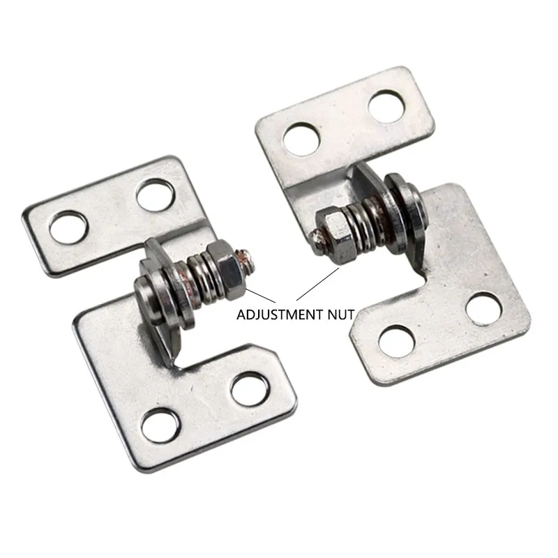
Use the model drawing, supplier datasheet, sample label, or approved work instruction to confirm the items below.
| Item to Confirm | Why It Matters | Status if Unknown |
|---|---|---|
| Exact hinge model and revision | Different revisions may use different adjustment ranges or locking details | Supplier Confirmation Required |
| Adjustment feature | Separates the true torque adjuster from mounting or retention hardware | Do not adjust |
| Increase and decrease direction | Prevents tightening the mechanism in the wrong direction | Supplier Confirmation Required |
| Correct tool and engagement depth | Reduces damage to the socket, screw, nut, or surrounding finish | To Be Confirmed |
| Permitted adjustment range | Prevents bottoming, over-compression, thread damage, or unsupported settings | Supplier Confirmation Required |
| Locking or retention method | Determines how the final setting is secured after tuning | Project-Specific |
| Adjustment condition | Some hinges may need the panel supported, unloaded, or positioned at a defined angle | Supplier Confirmation Required |
If this information is unavailable, stop at identification. A generic adjustment procedure cannot safely replace model-specific limits. The correct next step is to obtain the supplier drawing or work instruction, not to estimate the direction from another hinge.
Separate Torque Adjustment From Installation Problems
Adjustment cannot correct a hinge axis that is misaligned, a flexible mounting bracket, a panel rubbing the frame, or a cable harness pulling against movement. These conditions add uncontrolled resistance and can make a correct hinge feel too tight in one part of the arc and too loose in another.
Before changing the torque setting, move the panel slowly through the complete working angle and check:
- Both hinge axes are coaxial where multiple hinges are installed.
- Mounting leaves sit flat without being pulled into position by the screws.
- The panel, gasket, bezel, cable, and bracket do not rub during movement.
- Mounting screws, inserts, weld nuts, and backing plates are secure.
- The frame does not twist noticeably when the panel is moved.
- The cable harness and grounding strap do not add a changing spring force.
- The panel is not contacting a stop before the intended test angle.
A useful diagnostic is to support the panel so gravity is largely removed and then move it through the arc. If the resistance still changes sharply by angle, investigate alignment, interference, contamination, or mechanism damage before increasing the setting.
Define What an Acceptable Setting Must Do
“Feels good” is not a production acceptance criterion. The adjustment needs observable conditions that engineering, assembly, quality, and service personnel can evaluate the same way.
| Requirement | Example of a Controlled Definition | Project Status |
|---|---|---|
| Hold positions | Panel remains at the project-defined low, middle, and high working angles without visible drift during the specified observation period | Project-Specific |
| Movement quality | No sticking, sudden release, scraping, or sharp change in resistance through the working arc | Engineering Review |
| Operating effort | Opening and closing force remain within the user or equipment requirement | To Be Confirmed |
| Direction balance | Opening and closing behavior match the intended one-way or two-way function | Model-Specific |
| Multiple-hinge balance | No panel twist, bracket movement, or one hinge leading the other | Assembly-Specific |
| Setting retention | Adjustment does not move after locking, repeated operation, transport, or the selected verification condition | Project-Specific |
If the required hinge torque has not been calculated yet, complete that task before adjustment. The adjustment step should fine-tune a correctly sized hinge; it should not be used to rescue a hinge whose available range does not cover the panel load.
How to Adjust a Torque Hinge Step by Step
The procedure below is intentionally model-neutral. The supplier’s direction, tool, adjustment limit, and locking instruction take priority.
- Install the complete production-intent load. Include the display, cover, handle, wiring, trim, gasket, and any accessory that moves with the panel. Do not adjust using an empty door if the finished assembly will be significantly heavier.
- Support the panel before releasing a lock. Prevent the panel from dropping or rotating unexpectedly. Use a fixture or a second person where the panel mass or working position creates a handling risk.
- Record the starting position. Photograph or mark the adjustment feature and note the model, hinge location, initial reference mark, tool, panel configuration, and temperature if it affects the project.
- Release the approved locking feature. Loosen only the locknut, clamp, cap, or retaining feature identified in the supplier instruction. Do not loosen mounting screws to change torque.
- Adjust in small, controlled increments. Follow the supplier-defined increase or decrease direction. Use the same increment on matched hinges unless the supplier or engineering work instruction specifies a different method.
- Cycle the panel after each increment. Move it several times through the full working arc so the friction surfaces settle and the operator can distinguish real setting change from initial static breakaway.
- Test the required positions. Check the panel at the project-defined angles, including the worst gravity position and any working position affected by cable load or frame slope.
- Check movement in both directions. Confirm opening force, closing force, smoothness, and any intended directional difference. Do not judge the setting from one direction only.
- Stop before the adjustment limit. If the panel still drifts at the supplier-defined maximum setting, the hinge range, quantity, panel load, center of gravity, mounting stiffness, or installation needs engineering review.
- Apply the approved locking method. Hold the adjuster at the final position while securing the lock feature where required. Use thread-locking material only when the supplier and project documentation permit it.
- Repeat the functional test after locking. A locknut or clamp can shift the final setting. Recheck every acceptance position after the locking operation.
- Document the approved setting. Record the final reference, tool, locking method, panel configuration, verification result, and any allowed production tolerance.
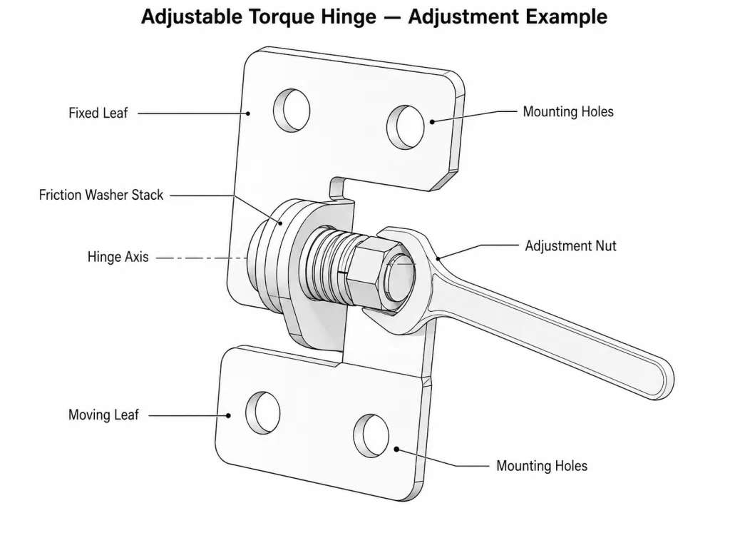
Do not publish a universal turn count: “Tighten one full turn” is not a valid instruction unless it belongs to an exact model and revision. Screw pitch, friction-stack design, factory preload, usable range, and locking method can all differ.
Adjust Multiple Torque Hinges as a Matched System
Two adjustable hinges on one panel should not be treated as two unrelated parts. Unequal settings can twist the panel, overload one mounting area, create uneven motion, or make one hinge wear faster.
Begin from a common baseline: same hinge model and revision, same initial adjustment reference, same tool, same increment, and the same locking procedure. Adjust both hinges in equal steps, then evaluate the assembled panel. If one hinge appears to need substantially more adjustment, first check:
- axis alignment and hinge spacing;
- panel and frame flatness;
- mounting-hole position and bracket stiffness;
- unequal cable or gasket load near one hinge;
- different hinge revisions or initial factory settings;
- damage, contamination, or abnormal play in one hinge.
Do not use one heavily adjusted hinge to compensate for a weak frame or a misaligned second hinge. The panel may hold during a short bench test while the mounting structure stores stress and the operation remains inconsistent.
Verify the Final Torque Hinge Setting on the Complete Assembly
The final setting is approved by panel behavior, not by the screw position alone. Verification should represent the actual equipment orientation and load.
Holding Check
Place the panel at every required working angle and observe it for the project-defined period. Include the position with the highest gravity moment. Where cables, hoses, or a gasket change the load by angle, test the positions where those forces are greatest.
Movement Check
Move the panel slowly and at normal user speed. Check for smooth resistance, sudden breakaway, stick-slip motion, scraping, bracket deflection, fastener movement, and a large difference between opening and closing unless directional behavior is intentional.
Repeatability Check
Operate the panel repeatedly, recheck the reference mark, and confirm that the setting has not shifted after the approved locking step. The number of verification cycles is project-specific. Do not describe a short adjustment check as a cycle-life qualification.
Environment Check
If the equipment operates across a meaningful temperature range or in vibration, perform the project-defined verification under those conditions. Lubricant behavior, panel load, seals, cables, and mounting stiffness may change. A room-temperature setting is a preliminary recommendation until the required operating condition is represented.
Functional panel checks confirm that the adjustment works in the application. When the setting also requires a numeric production limit, use a controlled hinge torque measurement method to record breakaway, running, opening, closing, or holding torque.
Lock and Document the Approved Setting
Adjustability creates value during development and service, but it can also create unit-to-unit variation. Once the desired behavior is approved, the setting needs a controlled way to remain stable and be reproduced.
The approved record may include:
- hinge model, revision, and supplier lot where traceability is required;
- panel model and complete moving mass configuration;
- hinge location, such as upper, lower, left, or right;
- starting reference mark and final reference mark;
- adjustment tool and approved direction;
- increment or setting method defined for that model;
- locking method and any specified locknut tightening value;
- required hold positions and observation method;
- opening and closing acceptance conditions;
- date, operator, sample status, and approval reference.
A paint witness mark can help show whether an adjustment feature has moved, but it does not lock the setting and does not replace a defined retention method. Likewise, an adhesive should not be added informally because it may affect serviceability, adjustment, temperature performance, or future disassembly.
Troubleshoot Torque Hinge Adjustment Problems
| Symptom | Likely Cause | What to Check Before Readjusting |
|---|---|---|
| Panel drifts at every angle | Setting too low, panel load increased, or hinge range is insufficient | Complete panel mass, center of gravity, hinge quantity, model range, and maximum permitted setting |
| Panel holds near vertical but drops near horizontal | Gravity moment increases with angle | Worst-case position and original torque calculation |
| Panel is difficult to move | Over-adjustment, misalignment, rubbing, or cable resistance | Support the panel, inspect the full arc, and compare loaded and unloaded movement |
| Motion is jerky or releases suddenly | Stick-slip, contamination, damaged mechanism, or distorted mounting | Hinge condition, bracket flatness, axis alignment, and supplier limits |
| One side moves before the other | Unequal settings or non-coaxial hinges | Common baseline, equal increments, hinge revision, and mounting geometry |
| Setting changes after locknut tightening | Adjuster moved during locking | Approved hold-tool method and post-lock verification |
| Setting loosens in service | Incorrect locking method, vibration, thread damage, or unsupported setting | Supplier-approved retention, thread condition, lock feature, and vibration requirement |
| Adjustment reaches its limit but panel still drifts | Wrong hinge range or system load outside the original assumption | Stop adjustment and return to engineering selection |
When the hinge reaches its permitted limit, additional force is not a valid adjustment strategy. Recalculate the requirement, review the panel load and mounting system, or select a different adjustable range.
Composite Engineering Scenario: Adjustable HMI Panel
Engineering example: This is a composite engineering scenario created to explain the selection logic. It is not a customer project record or product test claim.
For HMI-specific hinge selection, load definition, and mounting requirements, see our guide to torque hinges for HMI panels. This scenario focuses only on the adjustment and verification process.
An industrial HMI panel uses two adjustable torque hinges. The first prototype holds at the upper viewing angle but slowly closes near the lowest working angle. The assembly technician proposes tightening only the lower hinge because it is easier to reach.
Engineering first supports the panel and checks the complete arc. The lower cable bundle is pulling across the back of the panel, and the upper hinge bracket flexes slightly. Both conditions make the hinges appear mismatched.
The cable route is corrected and the bracket is reinforced before adjustment. The two hinges are returned to the same documented baseline. Both are then adjusted in equal, supplier-approved increments, cycled after each increment, and checked at the low, middle, and high working angles.
After the panel meets the movement and holding requirements, the locking features are secured using the model-specific work instruction. The team rechecks the panel because locking can shift the setting. The final reference marks, tool, panel configuration, and acceptance result are added to the assembly instruction.
The important result is not the number of turns. It is a repeatable procedure that separates cable and bracket problems from hinge torque, keeps both hinges balanced, and verifies the final setting after locking.
Verify the Adjustment on a Production-Intent Sample
A bench adjustment on an incomplete panel is a preliminary recommendation. Engineering review requires the real geometry and moving load. Sample approval applies only to the tested hinge model, panel configuration, mounting structure, locking method, and verification condition.
Before production release, confirm that:
- the production-intent panel and all mounted components are installed;
- both hinge locations and adjustment access match the released design;
- the adjustment method does not damage coatings, wiring, seals, or adjacent parts;
- the final setting passes the required angles after locking;
- multiple units can be adjusted within the defined production method;
- quality personnel can verify the result without relying only on operator feel;
- service instructions clearly state whether field readjustment is permitted;
- any change to panel mass, center of gravity, hinge revision, bracket, or locking method triggers review.
Production approval should not be inferred from one prototype if the adjustment instruction, fixture, model revision, or panel load changes.
Adjustable Torque Hinge Checklist
ADJUSTABLE TORQUE HINGE — SETUP AND VERIFICATION
-------------------------------------------------
IDENTIFICATION
[ ] Exact hinge model and revision confirmed
[ ] Supplier identifies the hinge as adjustable
[ ] Adjustment feature is distinguished from mounting and retention hardware
[ ] Increase/decrease direction confirmed
[ ] Tool, usable range, and adjustment condition confirmed
[ ] Approved locking method confirmed

ASSEMBLY CONDITION
[ ] Complete production-intent panel load installed
[ ] Hinge axes and brackets aligned
[ ] Mounting structure is rigid
[ ] No rubbing through the working arc
[ ] Cables, hoses, gasket, and grounding strap are represented
[ ] Panel is safely supported during adjustment

BASELINE
[ ] Initial adjustment reference recorded
[ ] Both hinges use the same baseline where applicable
[ ] Hold positions and movement criteria defined
[ ] Worst-case gravity position identified
[ ] Opening and closing behavior both included

ADJUSTMENT
[ ] Lock feature released only as instructed
[ ] Adjustment made in small controlled increments
[ ] Matched hinges adjusted equally unless otherwise specified
[ ] Panel cycled after each increment
[ ] Adjustment stopped before the supplier-defined limit

FINAL VERIFICATION
[ ] Panel holds at every required angle
[ ] Motion is smooth without sticking or sudden release
[ ] Operating effort is acceptable
[ ] No panel twist, bracket movement, or cable overload
[ ] Final result rechecked after locking
[ ] Setting remains stable during the project-defined verification

DOCUMENTATION
[ ] Final reference and locking method recorded
[ ] Tool and model-specific direction recorded
[ ] Panel configuration and hinge locations recorded
[ ] Production inspection method defined
[ ] Field-adjustment permission stated
For the earlier selection decision—whether the OEM should use a factory-set or adjustable mechanism—see our constant vs. adjustable torque hinge guide.
To calculate the required holding torque before adjustment, use the torque hinge calculation guide.
Cycle-life and torque-retention approval remain a separate task covered in the torque hinge cycle-life guide.
Frequently Asked Questions
Can every torque hinge be adjusted?
No. Only hinges specifically designed and documented as adjustable should be changed after manufacture. Constant torque hinges and sealed or factory-set mechanisms should not be modified unless the exact supplier instruction permits it.
Which direction increases torque on an adjustable hinge?
The direction is model-specific. Do not assume clockwise always increases resistance. Confirm the direction from the supplier drawing, label, or work instruction for the exact hinge model and revision.
How many turns should I use when adjusting a torque hinge?
There is no universal turn count. Use small, controlled increments within the supplier-defined adjustment range, cycle the panel after each increment, and stop when the complete assembly meets the approved holding and movement criteria.
Should two adjustable torque hinges use the same setting?
They should normally begin from the same documented baseline and be adjusted in equal increments. If one hinge needs a substantially different setting, inspect axis alignment, bracket stiffness, cable load, hinge revision, and mechanism condition before accepting unequal adjustment.
Why is the panel still drifting at the maximum setting?
The panel load or center of gravity may exceed the hinge range, the number of hinges may be insufficient, or installation and cable forces may be adding load. Stop adjusting at the supplier limit and return to engineering selection instead of applying more force.
Can thread-locking adhesive be added after adjustment?
Only when the hinge supplier and project documentation approve the product, location, quantity, temperature range, and future service method. An unapproved adhesive can affect adjustment, disassembly, contamination control, or the final setting.
Summary: Adjust the Assembly, Not Just the Screw
The correct answer to how to adjust a torque hinge is a controlled assembly procedure: confirm the exact model, remove installation interference, define acceptance conditions, adjust in supplier-approved increments, keep multiple hinges balanced, verify the complete panel after locking, and document the setting for production.
Do not copy the adjustment direction, turn count, tool, or locking method from another hinge. Those details require confirmation for the exact model and revision. The approved result is the panel behavior under the project condition, supported by a repeatable work instruction.
| Need Model-Specific Adjustment Information? Send the hinge model, drawing or photos, panel mass, center-of-gravity location, hinge quantity, working angles, mounting structure, and current problem. Contact our engineering team → |