-
+86 13720060320
-
lanna@haitangs.com

How to Specify Spring Hinge Closing Torque for Equipment Doors
To specify self-closing hinges for equipment doors, compare the minimum available return torque with the door’s opposing torque at the same installed angles. The hinge set must start the door from the required release positions and complete the intended closing movement, while keeping opening effort and closing impact within the project’s limits. Verify the result on the complete door.
A door that closes from fully open may still stop short when released near the latch. The spring’s return output may be lower there, just as a seal, latch ramp, or cable adds resistance. The highest torque number in a catalog does not establish whether the door will close from that position.
This article covers spring-return hinges for equipment doors that must move toward a defined closed position. If you are still deciding between a spring hinge and a separate closer, start with the spring hinge versus door closer comparison.
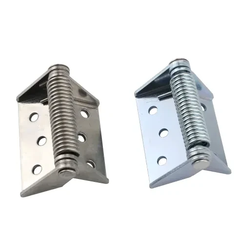
Define the Door’s Closing Movement
Define what the installed door must do: return to the frame, engage a push-to-close latch, or compress a gasket to a specified position. Include the actual frame, seal, latch, handle, and wiring.
With a manually operated compression latch, the hinge may only bring the door within reach; a person turns the handle to finish sealing. Specify the hinge’s part in that sequence.
Three details establish the motion requirement:
- Release range: the opening positions from which the door must start closing without an extra push. Include the smallest required release angle, not just the fully open position.
- Final state: the door position, latch engagement, and seal condition that count as closed. A door resting against a latch bolt has not necessarily latched.
- Installation state: the hinge-axis orientation, equipment mounting attitude, and operating conditions under which that movement is required.
Separate release range from maximum opening travel. Hold-open features, detents, or spring engagement zones can prevent automatic return through part of an otherwise permissible swing.
Side-opening doors and horizontal lids need different calculations
For an ideal side-opening door rotating about a vertical axis, gravity does not create a closing moment about that axis. Door mass still affects support loads, bearing friction, sag, and inertia. It does not become the required closing torque simply by multiplying mass by half the door width.
A horizontal-axis lid has an angle-dependent gravitational moment that may help or oppose the spring. An inclined axis can introduce gravity effects too. Southco’s torque-selection discussion distinguishes these orientations. Establish the side-opening door’s installed resistance instead of borrowing a lid-holding calculation.
Reading Closing Torque on a Datasheet
Spring hinge closing torque usually changes with angular position. Before comparing suppliers, identify the reference position on each drawing and translate it into the installed door angle. A catalog’s zero position may describe the hinge leaves rather than your equipment door against its frame.
For example, KIPP’s 0.7 N·m spring-closed hinge lists closing-spring values of 0.23 N·m at 0°, 0.45 N·m at 90°, and 0.7 N·m at 180°, using its catalog angle convention. Those are data for that manufacturer’s product, not ratings for HSP hinges. The example shows why “0.7 N·m” is incomplete without an angle.
Ask whether a quoted value is the spring’s theoretical torque or the measured output of the assembled hinge. Internal friction affects the output available during return. Guden’s spring-hinge torque note explains that spring and hinge friction cause hysteresis, and that its reported values correspond to a defined hinge position.
The force needed to wind a hinge open can therefore differ from the force it delivers while returning through the same angle. Use closing-direction output to assess self-closing performance. Use opening-direction measurements to assess what the operator must overcome.
Obtain closing-direction torque values at critical positions, or a torque-angle curve, with tolerances and test conditions. A maximum value without the required return data is insufficient for selection.
The Resistance Near the Closed Position
Closing resistance is not necessarily constant. A door may swing freely through most of its travel and meet a sharp increase when the seal first compresses or the latch bolt contacts its keeper. A wiring loop may add resistance earlier in the swing.
Match each resisting load to the angle where it occurs. Use the checks below to separate intended resistance from an installation problem before increasing spring torque.
| Resistance source | What changes during closing | Check before increasing torque |
|---|---|---|
| Hinge bearings and mounting strain | Resistance may persist through the swing or rise after final tightening. | Check the installed hinge line and mounting faces. Correct unintended binding, then repeat the resistance check. |
| Gasket contact | Resistance can rise sharply between first contact and the specified compression. | Confirm gasket seating, contact angle, and required compression. Retain the intended seal load in the torque requirement. |
| Latch and keeper | The latch ramp may introduce a local force peak before engagement. | Check alignment and confirm the latch supports the intended closing action. Measure the force needed to engage it. |
| Cables, hoses, or door-mounted parts | Bending, tension, or contact can add load at particular angles. | Inspect the final routing throughout travel. Remove unintended contact and measure the remaining routing load. |
| Pressure difference or equipment inclination | Operating conditions can assist or oppose return. | Check relevant fan states and installation attitudes. Include the greatest credible opposing condition. |
If resistance rises after the hinge leaves are tightened, investigate the mounting relationship. That observation is a reason to check alignment, not proof of a single cause. The industrial hinge axis alignment guide covers that diagnosis in detail.
For a preliminary installed-force check, a measured tangential force can be converted into an equivalent moment:
M = F × r, where F is the tangential force in newtons and r is the distance from the hinge axis to the pull point in meters. The result is in N·m. For a pull that is not tangential, use the perpendicular distance from the hinge axis to the force’s line of action instead of the distance to the pull point.
Record the angle, direction, pull point, and components active during the reading. With the spring still active, a gauge measures a net assembly response; that is not an independent measurement of seal or latch resistance. A controlled component test or an appropriately supported assembly with the return mechanism isolated may be needed to separate the contributions. Follow the hinge manufacturer’s instructions when isolating stored spring energy.
Also distinguish the force needed to restart a stationary door from the force needed to keep it moving. A slow sweep can miss the resistance that prevents a released door from starting. Detailed fixture and instrument guidance belongs in So messen Sie das Drehmoment eines Scharniers.
Avoid counting losses twice. If the supplier’s return value already includes internal hinge friction, exclude that same friction from the opposing-load total. Identify what an installed gauge reading includes before combining it with component data.
Set a Closing Torque Range and an Opening-Force Limit
The minimum return torque comes from the closing task. Opening effort, closing behavior, and component loads limit how much spring torque the assembly can use. A stronger spring may solve a closing shortfall while making the door harder to open.
For preliminary, low-speed screening of a freely moving door, use a consistent positive direction toward closed:
Available return torque + assisting torque > opposing torque
Apply this relationship across the required travel, using minimum available output and the greatest credible opposing load under the specified conditions. At each required release position, include the resistance to starting from rest. Equality leaves no reserve for variation.
This is a screening relationship, not a complete dynamic model. Acceleration, velocity-dependent damping, latch contact, and impact can change the result. If the door closes only after a push or a long swing, its momentum may be carrying it past an obstacle that the spring cannot overcome from rest.
Base the margin on output variation, assembly resistance, temperature, wear, and measurement uncertainty. Resolve missing inputs through supplier data or controlled tests; a universal percentage cannot establish the reserve your assembly needs.
Check the opening-force limit using opening-direction torque, not the net return value used for closure. At a stated handle position with a tangential pull, F = M / r. Here, M is the opening-direction resisting torque included in the calculation, and r is the handle’s distance from the hinge axis. Seal release, latch actuation, and cable loads need separate allowance unless they are already included in M.
Measure the complete door at the actual operating point. Moving the handle closer to the hinge axis increases the force required for the same resisting torque. A result measured at the outer edge is not interchangeable with one taken at an inset handle.
A return spring also does not inherently provide controlled closing speed. If a candidate closes reliably but strikes the frame too hard, assess the damping arrangement and closing requirement. Increasing or decreasing spring torque alone may not satisfy both.
Two Hinges With Enough Torque on Paper
On a rigid door with compatible, coaxial hinges, the closing contributions of the active springs add. A free-swinging companion hinge contributes support and friction, but no spring return. Count the hinges that actually provide closing torque, and use their values at the same installed angle.
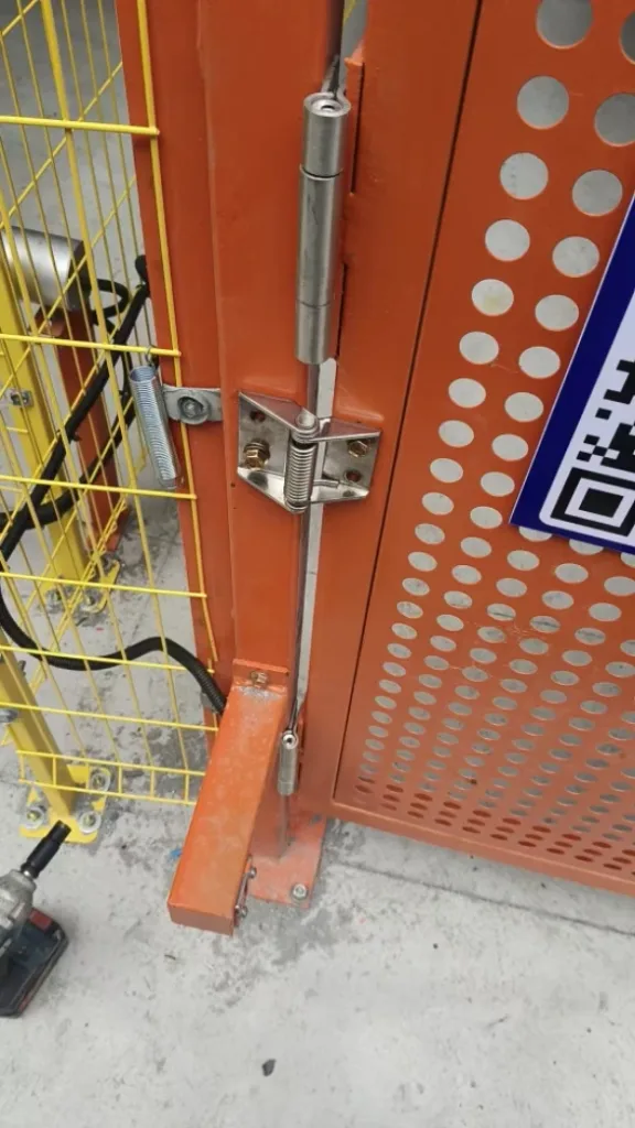
A door stops just before the latch engages
Consider an illustrative vertical-axis equipment door that must close from rest at 8° from closed. It has two spring hinges, each advertised at 1.0 N·m at a wide opening position. For this example, assume minimum net return output at the installed 8° position is 0.38 N·m per hinge. Assume the external resistance there is equivalent to a 3 N tangential force at 0.30 m, excluding friction already included in the hinge output.
- Available return torque: 2 × 0.38 = 0.76 N·m.
- Opposing torque: 3 × 0.30 = 0.90 N·m.
- Shortfall: 0.90 − 0.76 = 0.14 N·m at 8°.
The original pair fails this preliminary screen despite its combined advertised maximum of 2.0 N·m. First check whether the assumed opposing load represents required seal or latch operation, or correctable interference. If 0.90 N·m remains the design resistance, 0.45 N·m per hinge would only balance it; the specified minimum output must exceed that level with an appropriate reserve.
Request the candidate’s return output at the installed 8° position and the other critical angles. Then test the revised assembly from rest at 8°, through the required release range, and at the defined handle position. Accept it only when it reaches the specified final state and meets opening-force and closing-behavior limits. The calculation identifies a shortfall; it does not establish that an untested replacement will pass.
Adding another spring hinge changes more than the torque total. It also changes opening effort and adds another mounting interface that must follow the common axis. Structural load capacity and spring output remain separate checks; do not divide a door’s weight by the hinge count and treat the result as a closing-torque specification.
Where adjustable preload is available, the manufacturer’s permitted settings and travel limits apply. Do not assume a fixed spring hinge is field-adjustable, or that adding preload leaves the maximum usable opening angle unchanged.
Evidence to Request With the Sample
Identify the sample’s part number and revision, spring direction, mounting orientation, companion hinges, and preload setting. Matching its dimensions alone does not reproduce its return behavior.
The supporting data should answer four product-specific questions:
- What output is available? Closing-direction torque at the agreed angles, with the specified minimum, maximum, or tolerance.
- How was it obtained? Angle reference, measurement direction, speed or static method, temperature, and whether the reported output includes internal hinge friction.
- What happens after use? Return measurements after the agreed cycling or conditioning, using the same method and angle references as the initial check.
- What configuration was tested? The actual hinge or hinge set, spring setting, mounting arrangement, and any supporting load applied during measurement.
A cycle count alone does not show how much closing output remains. Compare initial and post-cycle return measurements near closed, using the same method, and repeat the functional release checks.
Include the temperatures and exposure conditions that can change spring output or assembly resistance, such as cold gaskets, lubricant changes, contamination, or corrosion. If a complete torque-angle curve is unavailable, agree on measurements at the door’s critical positions.
Release Tests on the Complete Equipment Door
Bench data identify a candidate. Installed tests establish its behavior with the actual door, frame, seals, latch, wiring, and damping arrangement.
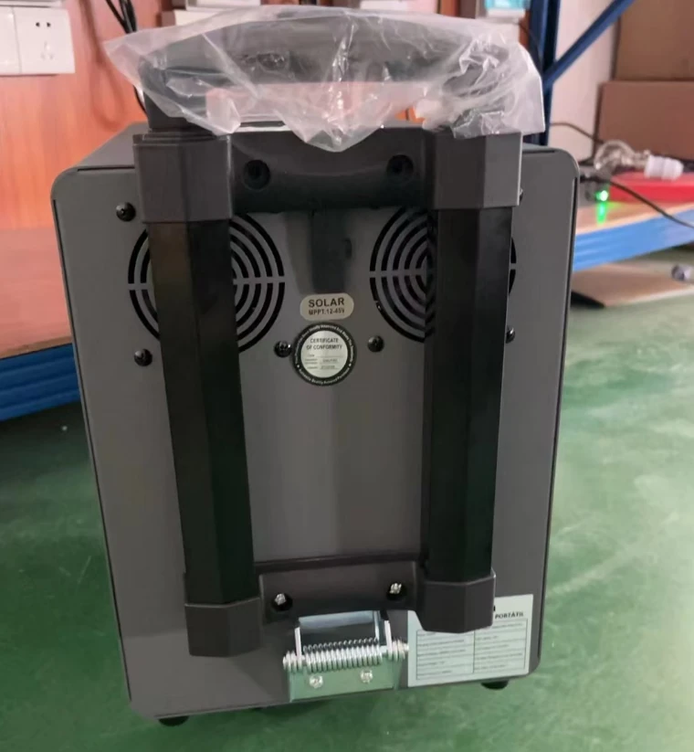
- Establish the final assembly condition. Use the specified mounting hardware and tightening condition, production-intent door mass and attachments, and the intended spring configuration. Check for unintended contact before testing.
- Release from the required positions. Include the minimum opening position, positions near seal or latch contact, a representative intermediate position, and the maximum required release position. Let the door settle before release so the test does not include an accidental push.
- Observe the approach to closed. Record any hesitation, stall, rebound, or abrupt impact, including the angle where it occurs. Verify the actual final state rather than judging it only by sound.
- Measure opening effort at the defined grip point. Evaluate the applicable starting and moving force limits, with latch operation identified separately when needed.
- Repeat under the specified conditions. Use the agreed number of specimens and repeats, operating attitudes, environmental conditions, and post-cycle checks. Record configuration changes and retest the affected requirement.
A stall, rebound, or hard impact needs an angle-specific record. For a stall, check contact and opposing load at that position before changing the spring setting. For a hard impact, review the damping arrangement as well as torque. Passing from fully open does not establish small-angle closure, and reaching the frame does not establish that the door remains latched.
A self-closing test does not certify a safety interlock or a sealed enclosure rating. Where either is required, its own system-level acceptance criteria still apply. Guard-specific considerations are covered in hinges for machine guards and safety access doors.
Put the Closing Requirement on the Drawing
Connect the hinge output to the installed motion on the drawing, and define the accepted behavior in the assembly specification. Another engineer should be able to interpret both without watching the original demonstration.
| Specification item | Was ist anzugeben? | How it will be checked |
|---|---|---|
| Installed angle reference | Closed-door datum, positive opening direction, hinge orientation, and equipment attitude. | Annotated assembly drawing and agreed reference positions. |
| Anzugsmoment | Minimum and maximum return output at agreed angles; identify per-hinge or total-set values and the test method. | Supplier torque-angle data or agreed position measurements. |
| Release and endpoint | Required release range and the final door, latch, and seal state. | Unassisted release tests on the complete assembly. |
| Opening effort | Allowable force at a defined grip point and direction, including how latch operation is treated. | Installed opening-force measurements. |
| Schließverhalten | Applicable time, impact, or rebound limits and the associated release condition. | Observed or instrumented closure using the agreed method. |
| Conditioned performance | Relevant environment, cycling, and the required closing torque and function afterward. | Repeated torque and assembly checks after conditioning. |
If torque is still being established, give the functional requirement and ask for a measurable output range. Treat that proposal as preliminary until the sample meets the specified door conditions.
Review the spring-loaded and self-closing hinge options against these requirements. For a torque review, send your door drawing and closing requirements, including the hinge-axis orientation, release range, latch or seal arrangement, any resistance readings, and the opening-force limit at the handle. Ask which candidate configuration and return-torque data are available before arranging a sample.
Self-Closing Hinge Torque Questions
What if the supplier lists door weight but no torque?
Ask what door geometry, hinge arrangement, release angle, and operating conditions produced that recommendation. A weight-based selection table can help shortlist products, but it does not define the return torque available against your seal or latch.
Must the hinge engage the latch automatically?
Only if that is part of the specified function and the latch supports automatic engagement. Some equipment doors return to a resting position and then require manual locking or compression. Describe the intended sequence before selecting the spring.