-
+86 13720060320
-
lanna@haitangs.com

Come specificare la coppia di chiusura delle cerniere a molla per le porte delle apparecchiature
Per specificare cerniere a chiusura automatica per sportelli di apparecchiature, confrontare la coppia di ritorno minima disponibile con la coppia opposta della porta agli stessi angoli di installazione. Il set di cerniere deve azionare la porta dalle posizioni di sgancio richieste e completare il movimento di chiusura previsto, mantenendo lo sforzo di apertura e l’impatto di chiusura entro i limiti previsti dal progetto. Verificare il risultato sulla porta completa.
Una porta che si chiude partendo dalla posizione completamente aperta potrebbe comunque arrestarsi prima di raggiungere il fermo quando viene rilasciata. In quel punto, la forza di ritorno della molla potrebbe essere inferiore, proprio come nel caso in cui una guarnizione, una rampa di chiusura o un cavo aggiungano resistenza. Il valore di coppia massimo riportato in un catalogo non garantisce che la porta si chiuda partendo da quella posizione.
Questo articolo tratta delle cerniere con ritorno a molla per gli sportelli delle apparecchiature che devono chiudersi in una posizione definita. Se siete ancora indecisi tra una cerniera a molla e un chiudiporta separato, iniziate con il Confronto tra cerniera a molla e chiudiporta.
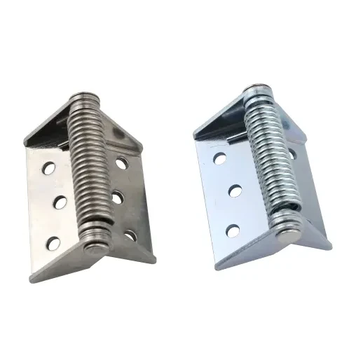
Definire il movimento di chiusura della porta
Definire le funzioni che la porta installata deve svolgere: tornare in posizione contro il telaio, innestare un chiavistello a chiusura automatica oppure comprimere una guarnizione fino a una posizione specificata. Includere il telaio vero e proprio, la guarnizione, il chiavistello, la maniglia e il cablaggio.
Con un fermo a compressione azionato manualmente, la cerniera può solo portare la porta a portata di mano; è necessario ruotare la maniglia per completare la chiusura. Specificare il ruolo della cerniera in tale sequenza.
Tre elementi dimostrano il requisito del movimento:
- Intervallo di rilascio: le posizioni iniziali da cui la porta deve iniziare a chiudersi senza bisogno di una spinta aggiuntiva. Indicare l’angolo di rilascio minimo richiesto, non solo la posizione di completa apertura.
- Stato finale: la posizione della porta, l’innesto del chiavistello e lo stato della guarnizione sono gli elementi che determinano se la porta è chiusa. Una porta che poggia contro il chiavistello non è necessariamente chiusa.
- Stato dell'installazione: l'orientamento dell'asse di articolazione, l'assetto di montaggio dell'apparecchiatura e le condizioni operative in cui è richiesto tale movimento.
Distanza di rilascio separata dalla corsa massima di apertura. Funzioni di blocco in posizione aperta, fermi o zone di innesto a molla possono impedire il ritorno automatico durante una parte di un’oscillazione altrimenti consentita.
Le porte con apertura laterale e i coperchi orizzontali richiedono calcoli diversi
Nel caso di una porta a apertura laterale ideale, che ruota attorno a un asse verticale, la gravità non genera un momento di chiusura attorno a tale asse. La massa della porta influisce comunque sui carichi di appoggio, sull’attrito dei cuscinetti, sul cedimento e sull’inerzia. La coppia di chiusura richiesta non si ottiene semplicemente moltiplicando la massa per la metà della larghezza della porta.
Un coperchio ad asse orizzontale presenta un momento gravitazionale che dipende dall'angolo e che può favorire o contrastare l'azione della molla. Anche un asse inclinato può determinare effetti gravitazionali. Approfondimento di Southco sulla selezione della coppia distingue questi orientamenti. Determinare la resistenza installata della porta ad apertura laterale, anziché ricorrere a un calcolo relativo al sostegno del coperchio.
Come leggere la coppia di serraggio in una scheda tecnica
La coppia di chiusura delle cerniere a molla varia solitamente in funzione della posizione angolare. Prima di confrontare i fornitori, individuate la posizione di riferimento su ciascun disegno e convertitela nell’angolo della porta una volta installata. La posizione zero indicata nel catalogo potrebbe riferirsi alle ante della cerniera piuttosto che alla porta del vostro impianto rispetto al telaio.
Ad esempio, il programma KIPP Cerniera con chiusura a molla da 0,7 N·m riporta valori della molla di chiusura pari a 0,23 N·m a 0°, 0,45 N·m a 90° e 0,7 N·m a 180°, secondo la convenzione angolare indicata nel catalogo. Si tratta di dati relativi al prodotto di quel produttore, non di valori nominali per le cerniere HSP. L’esempio mostra perché “0,7 N·m” è un dato incompleto senza l’indicazione dell’angolo.
Verificare se il valore indicato corrisponde alla coppia teorica della molla o alla coppia effettiva misurata della cerniera assemblata. L’attrito interno influisce sulla coppia disponibile durante il ritorno. Nota di Guden sulla coppia delle cerniere a molla spiega che l'attrito della molla e della cerniera provoca isteresi e che i valori riportati corrispondono a una posizione definita della cerniera.
La forza necessaria per aprire una cerniera può quindi differire dalla forza che essa esercita durante il ritorno attraverso lo stesso angolo. Utilizzare i valori rilevati nella direzione di chiusura per valutare le prestazioni di chiusura automatica. Utilizzare le misurazioni nella direzione di apertura per valutare la resistenza che l’operatore deve superare.
Ottenere i valori di coppia in direzione di chiusura nelle posizioni critiche, oppure una curva coppia-angolo, con le relative tolleranze e condizioni di prova. Un valore massimo senza i dati di ritorno richiesti non è sufficiente ai fini della selezione.
La resistenza in prossimità del livello di chiusura
La resistenza di chiusura non è necessariamente costante. Una porta può oscillare liberamente per gran parte della sua corsa e incontrare un brusco aumento di resistenza nel momento in cui la guarnizione inizia a comprimersi o il catenaccio entra in contatto con la sua sede. Un circuito elettrico può aggiungere resistenza già nelle prime fasi dell'oscillazione.
Abbinare ogni carico di resistenza all’angolo in cui si verifica. Utilizzare i controlli riportati di seguito per distinguere la resistenza prevista da un problema di installazione prima di aumentare la coppia della molla.
| Fonte di resistenza | Cosa cambia al momento del rogito | Verificare prima di aumentare la coppia |
|---|---|---|
| Cuscinetti a cerniera e sollecitazioni di montaggio | La resistenza potrebbe persistere per tutta la fase di oscillazione o di rialzo successiva all'ultimo inasprimento. | Controllare la linea della cerniera installata e le superfici di montaggio. Correggere eventuali attriti indesiderati, quindi ripetere il controllo della resistenza. |
| Contatto della guarnizione | La resistenza può aumentare notevolmente tra il primo contatto e la compressione specificata. | Verificare il corretto posizionamento della guarnizione, l’angolo di contatto e la compressione richiesta. Rispettare il carico di tenuta previsto nei valori di coppia richiesti. |
| Chiavistello e controspina | La rampa di innesto potrebbe causare un picco di forza locale prima dell'innesto. | Verificare l'allineamento e assicurarsi che il fermo garantisca la chiusura prevista. Misurare la forza necessaria per azionarlo. |
| Cavi, tubi flessibili o componenti montati sulle porte | La flessione, la trazione o il contatto possono aumentare il carico in determinati angoli. | Inspect the final routing throughout travel. Remove unintended contact and measure the remaining routing load. |
| Pressure difference or equipment inclination | Operating conditions can assist or oppose return. | Check relevant fan states and installation attitudes. Include the greatest credible opposing condition. |
If resistance rises after the hinge leaves are tightened, investigate the mounting relationship. That observation is a reason to check alignment, not proof of a single cause. The industrial hinge axis alignment guide covers that diagnosis in detail.
For a preliminary installed-force check, a measured tangential force can be converted into an equivalent moment:
M = F × r, where F is the tangential force in newtons and r is the distance from the hinge axis to the pull point in meters. The result is in N·m. For a pull that is not tangential, use the perpendicular distance from the hinge axis to the force’s line of action instead of the distance to the pull point.
Record the angle, direction, pull point, and components active during the reading. With the spring still active, a gauge measures a net assembly response; that is not an independent measurement of seal or latch resistance. A controlled component test or an appropriately supported assembly with the return mechanism isolated may be needed to separate the contributions. Follow the hinge manufacturer’s instructions when isolating stored spring energy.
Also distinguish the force needed to restart a stationary door from the force needed to keep it moving. A slow sweep can miss the resistance that prevents a released door from starting. Detailed fixture and instrument guidance belongs in Come misurare la coppia delle cerniere.
Avoid counting losses twice. If the supplier’s return value already includes internal hinge friction, exclude that same friction from the opposing-load total. Identify what an installed gauge reading includes before combining it with component data.
Set a Closing Torque Range and an Opening-Force Limit
The minimum return torque comes from the closing task. Opening effort, closing behavior, and component loads limit how much spring torque the assembly can use. A stronger spring may solve a closing shortfall while making the door harder to open.
For preliminary, low-speed screening of a freely moving door, use a consistent positive direction toward closed:
Available return torque + assisting torque > opposing torque
Apply this relationship across the required travel, using minimum available output and the greatest credible opposing load under the specified conditions. At each required release position, include the resistance to starting from rest. Equality leaves no reserve for variation.
This is a screening relationship, not a complete dynamic model. Acceleration, velocity-dependent damping, latch contact, and impact can change the result. If the door closes only after a push or a long swing, its momentum may be carrying it past an obstacle that the spring cannot overcome from rest.
Base the margin on output variation, assembly resistance, temperature, wear, and measurement uncertainty. Resolve missing inputs through supplier data or controlled tests; a universal percentage cannot establish the reserve your assembly needs.
Check the opening-force limit using opening-direction torque, not the net return value used for closure. At a stated handle position with a tangential pull, F = M / r. Here, M is the opening-direction resisting torque included in the calculation, and r is the handle’s distance from the hinge axis. Seal release, latch actuation, and cable loads need separate allowance unless they are already included in M.
Measure the complete door at the actual operating point. Moving the handle closer to the hinge axis increases the force required for the same resisting torque. A result measured at the outer edge is not interchangeable with one taken at an inset handle.
A return spring also does not inherently provide controlled closing speed. If a candidate closes reliably but strikes the frame too hard, assess the damping arrangement and closing requirement. Increasing or decreasing spring torque alone may not satisfy both.
Two Hinges With Enough Torque on Paper
On a rigid door with compatible, coaxial hinges, the closing contributions of the active springs add. A free-swinging companion hinge contributes support and friction, but no spring return. Count the hinges that actually provide closing torque, and use their values at the same installed angle.
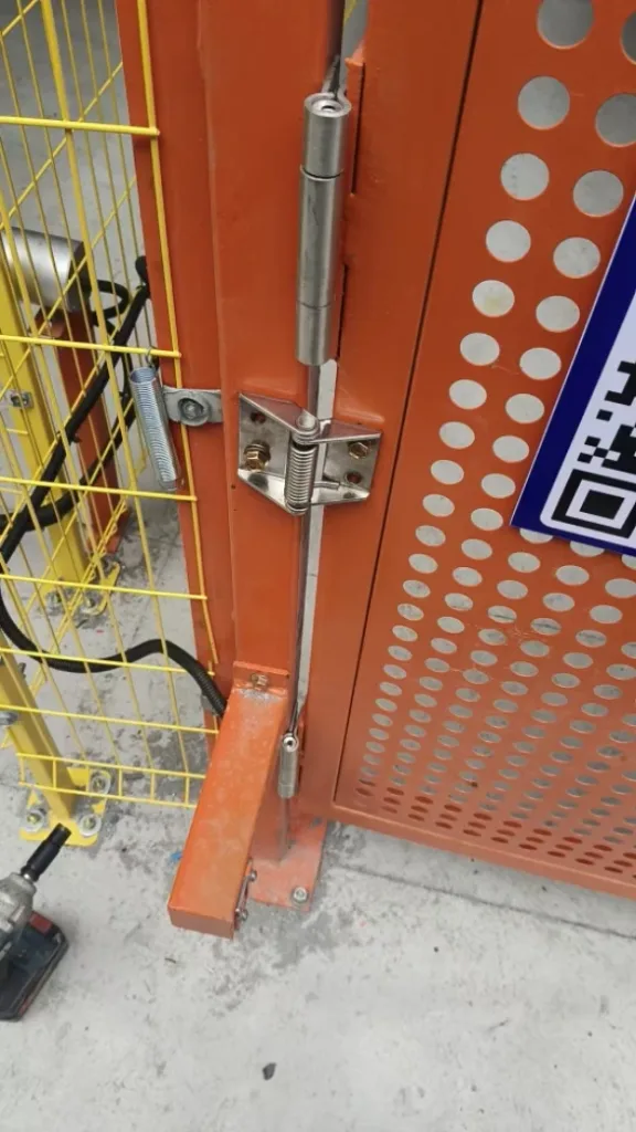
A door stops just before the latch engages
Consider an illustrative vertical-axis equipment door that must close from rest at 8° from closed. It has two spring hinges, each advertised at 1.0 N·m at a wide opening position. For this example, assume minimum net return output at the installed 8° position is 0.38 N·m per hinge. Assume the external resistance there is equivalent to a 3 N tangential force at 0.30 m, excluding friction already included in the hinge output.
- Available return torque: 2 × 0.38 = 0.76 N·m.
- Opposing torque: 3 × 0.30 = 0.90 N·m.
- Shortfall: 0.90 − 0.76 = 0.14 N·m at 8°.
The original pair fails this preliminary screen despite its combined advertised maximum of 2.0 N·m. First check whether the assumed opposing load represents required seal or latch operation, or correctable interference. If 0.90 N·m remains the design resistance, 0.45 N·m per hinge would only balance it; the specified minimum output must exceed that level with an appropriate reserve.
Request the candidate’s return output at the installed 8° position and the other critical angles. Then test the revised assembly from rest at 8°, through the required release range, and at the defined handle position. Accept it only when it reaches the specified final state and meets opening-force and closing-behavior limits. The calculation identifies a shortfall; it does not establish that an untested replacement will pass.
Adding another spring hinge changes more than the torque total. It also changes opening effort and adds another mounting interface that must follow the common axis. Structural load capacity and spring output remain separate checks; do not divide a door’s weight by the hinge count and treat the result as a closing-torque specification.
Where adjustable preload is available, the manufacturer’s permitted settings and travel limits apply. Do not assume a fixed spring hinge is field-adjustable, or that adding preload leaves the maximum usable opening angle unchanged.
Evidence to Request With the Sample
Identify the sample’s part number and revision, spring direction, mounting orientation, companion hinges, and preload setting. Matching its dimensions alone does not reproduce its return behavior.
The supporting data should answer four product-specific questions:
- What output is available? Closing-direction torque at the agreed angles, with the specified minimum, maximum, or tolerance.
- How was it obtained? Angle reference, measurement direction, speed or static method, temperature, and whether the reported output includes internal hinge friction.
- What happens after use? Return measurements after the agreed cycling or conditioning, using the same method and angle references as the initial check.
- What configuration was tested? The actual hinge or hinge set, spring setting, mounting arrangement, and any supporting load applied during measurement.
A cycle count alone does not show how much closing output remains. Compare initial and post-cycle return measurements near closed, using the same method, and repeat the functional release checks.
Include the temperatures and exposure conditions that can change spring output or assembly resistance, such as cold gaskets, lubricant changes, contamination, or corrosion. If a complete torque-angle curve is unavailable, agree on measurements at the door’s critical positions.
Release Tests on the Complete Equipment Door
Bench data identify a candidate. Installed tests establish its behavior with the actual door, frame, seals, latch, wiring, and damping arrangement.
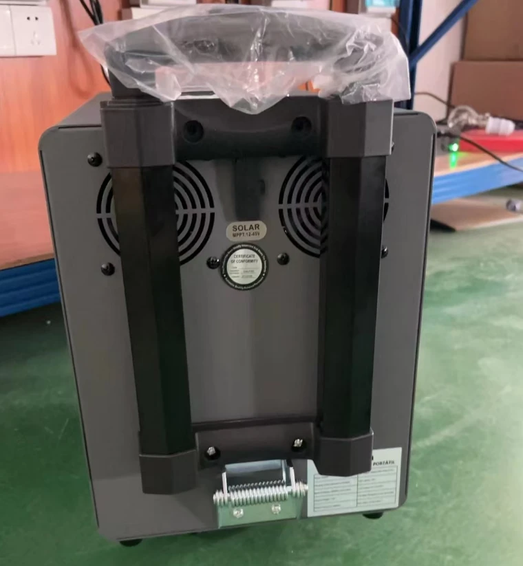
- Establish the final assembly condition. Use the specified mounting hardware and tightening condition, production-intent door mass and attachments, and the intended spring configuration. Check for unintended contact before testing.
- Release from the required positions. Include the minimum opening position, positions near seal or latch contact, a representative intermediate position, and the maximum required release position. Let the door settle before release so the test does not include an accidental push.
- Observe the approach to closed. Record any hesitation, stall, rebound, or abrupt impact, including the angle where it occurs. Verify the actual final state rather than judging it only by sound.
- Measure opening effort at the defined grip point. Evaluate the applicable starting and moving force limits, with latch operation identified separately when needed.
- Repeat under the specified conditions. Use the agreed number of specimens and repeats, operating attitudes, environmental conditions, and post-cycle checks. Record configuration changes and retest the affected requirement.
A stall, rebound, or hard impact needs an angle-specific record. For a stall, check contact and opposing load at that position before changing the spring setting. For a hard impact, review the damping arrangement as well as torque. Passing from fully open does not establish small-angle closure, and reaching the frame does not establish that the door remains latched.
A self-closing test does not certify a safety interlock or a sealed enclosure rating. Where either is required, its own system-level acceptance criteria still apply. Guard-specific considerations are covered in hinges for machine guards and safety access doors.
Put the Closing Requirement on the Drawing
Connect the hinge output to the installed motion on the drawing, and define the accepted behavior in the assembly specification. Another engineer should be able to interpret both without watching the original demonstration.
| Specification item | Cosa indicare | How it will be checked |
|---|---|---|
| Installed angle reference | Closed-door datum, positive opening direction, hinge orientation, and equipment attitude. | Annotated assembly drawing and agreed reference positions. |
| Coppia di serraggio | Minimum and maximum return output at agreed angles; identify per-hinge or total-set values and the test method. | Supplier torque-angle data or agreed position measurements. |
| Release and endpoint | Required release range and the final door, latch, and seal state. | Unassisted release tests on the complete assembly. |
| Opening effort | Allowable force at a defined grip point and direction, including how latch operation is treated. | Installed opening-force measurements. |
| Comportamento di chiusura | Applicable time, impact, or rebound limits and the associated release condition. | Observed or instrumented closure using the agreed method. |
| Conditioned performance | Relevant environment, cycling, and the required closing torque and function afterward. | Repeated torque and assembly checks after conditioning. |
If torque is still being established, give the functional requirement and ask for a measurable output range. Treat that proposal as preliminary until the sample meets the specified door conditions.
Review the spring-loaded and self-closing hinge options against these requirements. For a torque review, send your door drawing and closing requirements, including the hinge-axis orientation, release range, latch or seal arrangement, any resistance readings, and the opening-force limit at the handle. Ask which candidate configuration and return-torque data are available before arranging a sample.
Self-Closing Hinge Torque Questions
What if the supplier lists door weight but no torque?
Ask what door geometry, hinge arrangement, release angle, and operating conditions produced that recommendation. A weight-based selection table can help shortlist products, but it does not define the return torque available against your seal or latch.
Must the hinge engage the latch automatically?
Only if that is part of the specified function and the latch supports automatic engagement. Some equipment doors return to a resting position and then require manual locking or compression. Describe the intended sequence before selecting the spring.