-
+86 13720060320
-
lanna@haitangs.com

الخلوص بين مسمار المفصلة والجزء المقابل: الملاءمة، والتفاوت المسموح به، وخطر الانحشار
قد يجتاز مسمار المفصلة فحص قطره، ومع ذلك يتعطل بعد التشطيب أو التسخين أو التجميع النهائي. كما أن العطل المعاكس ممكن أيضًا: حيث يدور المفصل بحرية، لكن الفجوة الكبيرة جدًّا تتسبب في ارتطام الباب أو انزياحه أو اختلال محاذاة المزلاج. والمعيار المفقود هنا ليس قطرًا اسميًّا آخر، بل هو نطاق خلوص محدد لمسمار المفصلة عند نقطة التلامس التي تدور فعليًّا.
يُجيب الشرط المفيد المتعلق بالتوافق بين الدبوس والفتحة على سؤالين. ما هو أكبر فراغ يمكن للمنتج تحمله قبل أن يصبح التلاعب الحر غير مقبول؟ وما هو أصغر فراغ متبقي لا يزال يسمح بالحركة في أسوأ ظروف التشغيل؟ تحدد حدود الدبوس والتجويف النطاق الأولي. أما تراكم الطلاء النهائي، ودرجة الحرارة، وهندسة المفصل المشكل، ومحاذاة التركيب، ومواد التشحيم، والتلوث، والتآكل، فتغير ما يتبقى من هذا النطاق.
النطاق: “يُقصد بـ”الخلوص» هنا الفجوة الشعاعية أو القطرية بين الدبوس والتجويف أو الجلبة التي يدور عليها. وهو ليس المسافة المحورية اللازمة لرفع الباب عن مفصلته. وتندرج هذه المهمة المنفصلة ضمن دليل مسافة الفصل عند الإقلاع وتثبيت الدبوس.
قم أولاً برسم خريطة للواجهة الدوارة
قد يمر مسمار مفصلي واحد عبر عدة مفاصل، ولكن لا ينبغي أن يكون التوافق بين كل مسمار وفتحة هو نفسه. فقد يكون المسمار مثبتًا بشكل يمنع الدوران في إحدى المفاصل، بينما يدور في المفاصل الأخرى. وقد يدور داخل جلبة قابلة للاستبدال يتم تثبيت قطرها الخارجي في غلاف. قد يحتاج الدبوس القابل للإزالة إلى خلوص تجميع على طول طوله الكامل مع الاستمرار في استخدام منطقة محمل خاضعة للتحكم. إذا طبق الرسم ملاحظة قطر عامة واحدة على جميع تلك الأسطح، فقد يؤدي ذلك إلى حدوث حركة في الأماكن التي تتطلب التثبيت أو حدوث تداخل في الأماكن التي تتطلب الدوران.
حدد كل منطقة وظيفية على مقطع عرضي. قم بتسمية العنصر الذي يدور، والعنصر الذي يظل ثابتًا من حيث الدوران، والطول المحوري الذي يتحمل خلاله الزوج الحمل. حدد أيضًا التثبيت بالوتد، أو التثبيت بالضغط، أو التخريش، أو اللحام، أو الحلقة المثبتة، أو الطرف ذي الرأس، أو أي ميزة تثبيت أخرى. يمنع التثبيت المحوري انزياح الدبوس. ويحدد التثبيت الدوراني ما إذا كان الدبوس يمكن أن يدور بالنسبة للمفصل. ويتحكم الخلوص التشغيلي في الأسطح الدوارة المقصودة. هذه الوظائف مترابطة، لكنها ليست متطلبات قابلة للتبادل.
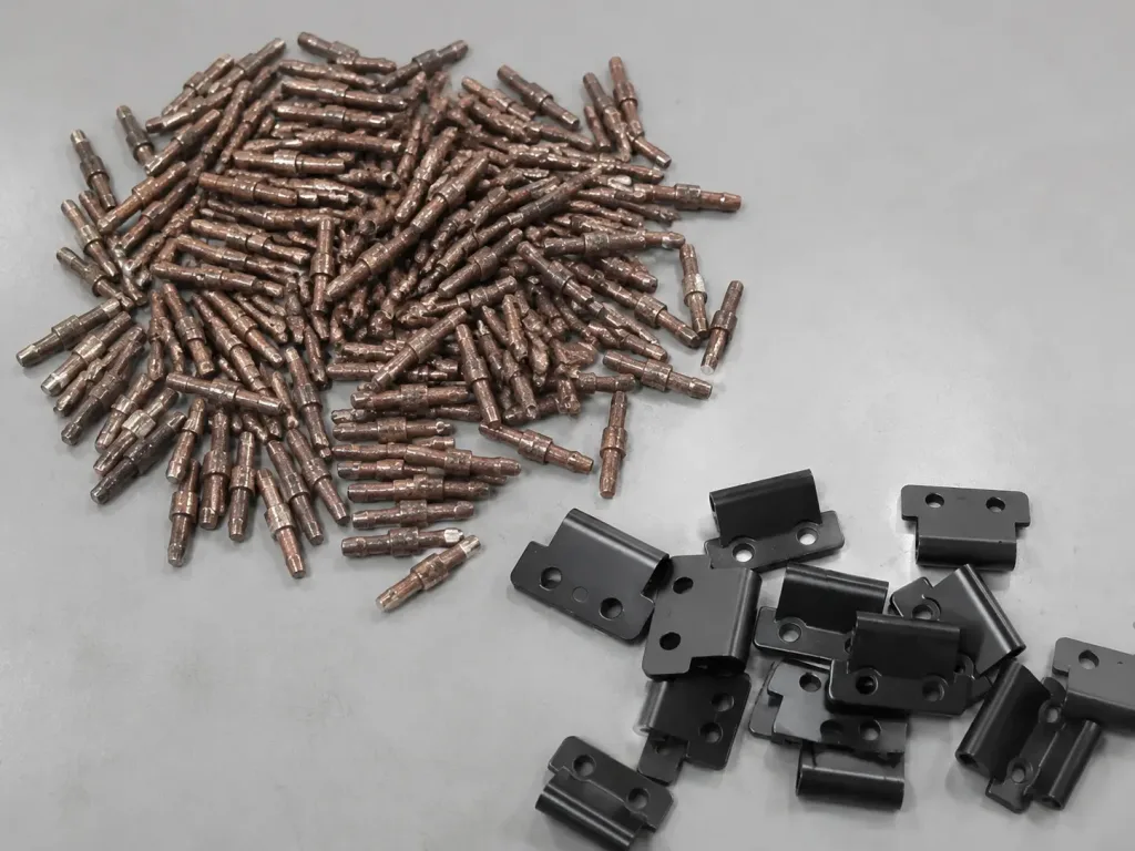
مسامير المفصلات ومكونات المفصلات في مرحلة الإنتاج. يعتمد الفراغ التشغيلي النهائي على الحدود المحددة للمسامير والتجاويف بعد عمليات التشطيب والتجميع.
| بنية المحور | واجهة مصممة للتدوير | واجهة مصممة لتبقى ثابتة من حيث الدوران | قرار الملاءمة | يحدث الفشل في حالة الخلط بين المناطق |
|---|---|---|---|---|
| دبوس مثبت دورانيًّا ومثبت محوريًّا في المفصل المركزي | تثبيت الدبوس في فتحات المفاصل الخارجية | ثبّته في فتحة المفصل المركزي الثابتة | حدد الخلوص التشغيلي عند المفاصل الخارجية؛ وحدد التثبيت الدوراني والاحتفاظ المحوري بشكل منفصل عند المركز | تتحول الدبوسات أو تنتقل عن مكانها الذي ينبغي أن تكون ثابتة فيه، أو تتعطل المفاصل الخارجية |
| دبوس غير محكم وقابل للإزالة | مناطق المحامل المحددة في المشروع على طول الدبوس | لن تكون هناك واجهة ثابتة دائمة ما لم تتم إضافة ميزة محلية | السماح بالإدخال والإخراج مع التحكم في أقطار تحمل الحمولة ودرجة الاستقامة | تركيب سهل مع اهتزاز مفرط، أو ملاءمة اسمية جيدة لا يمكن تركيبها من خلال مفاصل متوازية |
| دبوس يدور داخل جلبة | مقارنة القطر الخارجي للدبوس بالقطر الداخلي للجلبة | القطر الخارجي للجلبة مقارنةً بغلافها | حدد ملاءمة التشغيل بين الدبوس والجلبة وملاءمة تثبيت الجلبة كواجهةين مختلفتين | تدور الجلبة داخل الغلاف، أو تنغلق الجلبة المثبتة وتثبت على الدبوس |
| دبوس مثبت من كلا الطرفين | القطر الداخلي للجلبة أو العنصر المركزي مقابل الدبوس | ثبت الأطراف على الدعامات | التحكم في محاذاة الدعامات وكذلك زوج قطر الدوران | يخضع كلا الدعامتين للفحص بنجاح، لكنهما يتسببان في انحناء الدبوس أو تحميل الجلبة بشكل جانبي بعد التجميع |
يحتوي صف الجلبات على تفصيل مهم. فقد يؤدي ضغط جلبة ذات جدار رقيق داخل مبيتها إلى تقليل القطر الداخلي النهائي. ولذلك، قد يقوم المورد بمراقبة القطر الداخلي للجلبة بعد التركيب، وليس فقط عندما تكون مكونًا منفصلاً. ولا تثبت شهادة ما قبل التركيب ملاءمة التشغيل بعد التركيب ما لم يكن تأثير التجميع معروفًا.
الخلوص الشعاعي والخلوص القطري ليسا نفس الشيء
دع D سواء كان ذلك القطر الداخلي للثقب أو الجلبة المركبة و d ليكن هذا هو القطر الخارجي للمسمار. ويُعرف الخلوص القطري بأنه الفرق بين هذين القطرين. أما الخلوص الشعاعي فهو نصف تلك القيمة عندما يكون المسمار والتجويف دائرتين مثاليتين ويكون محوراهما متوازيين.
Cd = D − d و Cr = (D − d) / 2
Cd هو الخلوص القطري. Cr هو الخلوص الشعاعي.
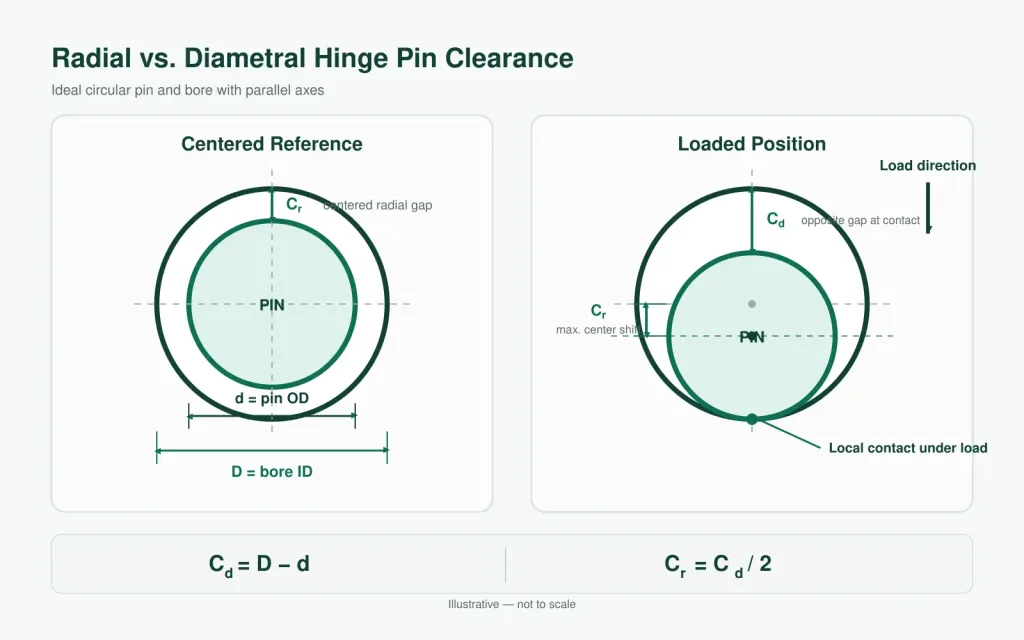
إن الاكتفاء بكتابة كلمة “الخلوص” فقط قد يؤدي إلى خطأ في التفسير بنسبة اثنين إلى واحد. يجب أن تستند الرسومات وورقة الحسابات وتقرير الفحص إلى نفس الأساس. ويُعد الخلوص القطري ملائمًا لأنه يُستمد مباشرةً من القطر الخارجي المُقاس للمسمار والقطر الداخلي المُقاس للتجويف. أما الخلوص الشعاعي فهو مفيد عند التحقق من الفجوة المادية المتبقية على أحد الجانبين أو عند تحديد هامش التداخل المحلي.
لا يمكن لأي من هاتين القيمتين أن تتنبأ تلقائيًّا بحركة حافة الباب. فقد يتحرك الدبوس داخل التجويف، كما يمكن لمنطقة المحمل القصيرة أن تميل أيضًا. تؤثر المفاصل المتعددة، والمسافة بينها، وطول المحمل، واتجاه الحمل، وصلابة مصراع الباب، وقيود المزلاج على شكل الفجوة التي تظهر عند الباب. قم بالتحكم في زوج القطر أولاً، ثم تحقق من الفراغ الحر على المفصلة المُجمَّعة أو المعدات عند نقطة قياس محددة.
قاعدة الرسم: استخدم مصطلح “الخلوص القطري” أو “الخلوص الشعاعي”. تجنب التبديل بين المصطلحين في رسائل البريد الإلكتروني الموجهة إلى الموردين، وأوراق الفحص، وملاحظات CAD.
هناك حدان يتحكمان في «الملاءمة المصنعة»
الحجم الاسمي لا يحدد الفراغ؛ بل تحدد ذلك التوليفات الحدية. ويحدث أصغر فراغ مصنّع عندما يكون التجويف عند أدنى قطر مسموح به، ويكون الدبوس عند أقصى قطر له. أما أكبر فراغ فيحدث عندما يكون التجويف في أكبر حجم له، ويكون الدبوس في أصغر حجم له.
Cدقيقة = ددقيقة − دالحد الأقصى
Cالحد الأقصى = دالحد الأقصى − ددقيقة
هذه هي الحدود القصوى والدنيا للقطر في ظل ظروف القياس المذكورة.
إذا Cدقيقة إذا كانت القيمة سالبة، فإن حدود الحجم تسمح بحدوث تداخل. وقد يكون ذلك مقصودًا في منطقة ثابتة دورانيًّا أو منطقة تركيب بالضغط، لكنه لا يضمن ملاءمة التشغيل. إذا Cالحد الأقصى إذا تجاوزت هذه القيمة الحد المسموح به للعب الوظيفي، فإن الرسم يسمح بوجود مفصل غير محكم حتى لو اجتاز كل مكون على حدة الفحص.
إن نظام ISO 286 الخاص بالتفاوتات والتوافقات توفر هذه المواصفة طريقة معترف بها للتعبير عن مناطق التفاوت المسموح بها للفتحات والأعمدة. تحدد المواصفة ISO 286-1 نظام الترميز وأسس التفاوتات والانحرافات والتوافقات؛ بينما توفر المواصفة ISO 286-2 القيم الخاصة بفئات التفاوت الشائعة الاستخدام. يمكن للنظام تحديد العلاقة بين الأحجام. لكنه لا يختار التوافق الصحيح للمفصلة ولا يأخذ في الاعتبار تراكم الطلاء، أو انكماش الجلبة المركبة، أو التدرجات الحرارية، أو اختلال محاذاة المفصل، أو التلوث، أو حالة مادة التشحيم، أو التشوه تحت الحمل، أو الحركة المقبولة للباب. وتظل هذه العوامل من متطلبات المشروع.
لا تختار فئة المقاس المألوفة بشكل افتراضي
قد يكون التعيين الملائم الذي تم نسخه من آلية أخرى ضيقًا جدًّا بالنسبة للمفاصل المشكلة والتلوث الخارجي، أو فضفاضًا جدًّا بالنسبة لباب الجهاز الذي يجب أن يتوافق مع المزلاج بشكل ثابت. طريقة التصنيع مهمة. يمكن أن تتميز الجلبة المُوسعة بهندسة مختلفة عن عدة مفاصل ملفوفة لا يتم محاذاة بعضها البعض إلا أثناء التجميع. وينطبق الأمر نفسه على طول المحمل، واستقامة الدبوس، واستدارة التجويف، والمسافة بين مناطق الدعم.
ابدأ بالحد الأقصى والحد الأدنى للخلوص الوظيفي. ثم حدد حدود الدبوس والتجويف التي يمكن لخط الإنتاج قياسها والحفاظ عليها. إذا كانت فئة الملاءمة وفقًا لمعايير ISO تفي بهذه المتطلبات بالكامل، فاستخدمها. فالفئة هي نتيجة القرار الهندسي، وليست بديلاً عنه.
يمكن أن يؤدي تراكم الطلاء إلى إزالة الفجوة
قد لا تعكس الأبعاد التي يتم قياسها قبل الطلاء أو الطلاء المعدني أو أي تشطيب آخر ينتج عنه تراكم قابل للقياس، مدى ملاءمة الأجزاء عند التجميع. فالطبقة المودعة على الدبوس تضيف مادة حول القطر الخارجي، بينما الطبقة المودعة داخل التجويف تقلل من المساحة المتوفرة في القطر الداخلي. وعندما يخضع كلا السطحين الوظيفيين لمثل هذا التشطيب، تتراكم تأثيراتهما معًا.
Cانتهى ≈ Cمشغولة آلياً − 2 طندبوس − 2 طنثقب
tدبوس و tثقب هي سماكات الطبقات المودعة شعاعيًّا على الأسطح المتلامسة. جميع المصطلحات تُقاس بالقطر باستثناء قيمتي السماكة الشعاعية المذكورتين. استخدم حدود العملية الخاصة بالمناطق الفعلية المُغطاة أو غير المُغطاة.
هذا التعبير يمثل علاقة بين الفراغ والميزانية، وليس ادعاءً بأن كل طبقة طلاء تترسب بشكل موحد. فقد تظهر الأجزاء الفعلية تباينًا في السماكة بالقرب من الحواف، والتجاويف، ونقاط التلامس، والرفوف، والمصارف، والمناطق المحمية. وقد يمتد الطلاء ليشكل جسرًا عبر طرف المفصل. وقد يكون للمسمار المطلي نقطة أعلى تختلف عما يوحي به متوسط سماكته. بالنسبة للطلاءات التحويلية أو المعالجات السطحية الأخرى، استخدم بيانات التغير الأبعادي المؤهلة الخاصة بالعملية بدلاً من افتراض وجود طبقة مترسبة موحدة. يجب أن يحدد الرسم ما إذا كانت الأبعاد النهائية للمسمار والتجويف تنطبق قبل التشطيب أم بعده، وأي الأسطح يتم تغطيتها.
كما يجب مراجعة تسلسل التجميع. فقد تنكمش الجلبة التي تم تشكيلها حسب المقاس ثم ضغطها داخل الغلاف. ويمكن أن تتكيف البطانة اللينة للمحمل مع ضغط التركيب. وقد يؤدي التثبيت بالقرب من التجويف العامل إلى ظهور نقطة مرتفعة محلية، حتى وإن كان القطر المقاس بعيدًا عن نقطة التثبيت مقبولًا. وعندما تؤدي العملية إلى تغيير القطر الداخلي التشغيلي، يجب فحص هذا القطر بعد العملية أو إثبات وجود علاقة مؤكدة بينهما.
قد يجتاز المكون الاختبار، ومع ذلك قد يفشل الوصلة. تخيل دبوسًا بحجمه الأقصى وتجويفًا بحجمه الأدنى. يمر كلاهما عبر عملية التشطيب. ثم يخضع الدبوس لعملية تشطيب بالقرب من الحد الأعلى للسماكة، بينما يتعرض التجويف لتراكم داخلي، ويؤدي التثبيت إلى تكوين تضييق موضعي صغير. في درجة حرارة الغرفة، تتحرك المفصلة بقوة انفصال عالية؛ وبعد التسخين تتوقف عن الحركة. بدت جميع المواصفات الاسمية معقولة، لكن المتطلبات لم تتحكم أبدًا في واجهة الدوران النهائية. هذا سيناريو هندسي توضيحي، وليس سجلًا لمشروع عميل أو ادعاءً يتعلق باختبار منتج.
تؤثر درجة الحرارة على ملاءمة ملابس الجري
تتغير أبعاد الدبوس والفتحة مع تغير درجة الحرارة. وفي حالة اختلاف المواد أو درجات الحرارة، قد يتقلص الفراغ أو يتسع. وتُعد العلاقة القطرية من الدرجة الأولى الواردة أدناه مفيدة في التقدير الأولي عندما يظل التمدد خطيًّا تقريبًا ولا تتعرض الهندسة التشكيلية لتشوهات كبيرة.
C(T) ≈ D0(1 + αbΔTb) − d0(1 + αpΔTp)
α هو معامل التمدد الحراري المطبق؛ والأرقام السفلية b و p يرجى الرجوع إلى العنصر المفرغ والمسمار.
يمكن أن يؤدي ارتفاع معدل تمدد الدبوس، أو ارتفاع درجة حرارة الدبوس، أو وجود تجويف مقيد إلى تقليل الفجوة. أما إذا تمدد عنصر التجويف أكثر من الدبوس، فقد يؤدي ذلك إلى زيادة الفجوة. وعندما يكون الدبوس والتجويف من نفس المادة ويصلان إلى نفس درجة الحرارة الموحدة، يتغير قطر كل منهما في نفس الاتجاه، وتتغير الفجوة الأصلية تبعًا لذلك؛ فهي لا تختفي ببساطة. ولا ينطبق هذا التبسيط الملائم على دبوس ساخن داخل غلاف أكثر برودة، أو جلبة مُركَّبة في إطار مختلف، أو مفصل مُشكَّل مشوه بفعل مصدر حرارة قريب.
استخدم بيانات المواد المناسبة للدرجة الفعلية ونطاق درجة الحرارة. ثم أضف المساهمة الحرارية إلى أسوأ سيناريو ممكن من حيث الحجم والتشطيب. وإذا كانت درجة الحرارة تؤثر أيضًا على لزوجة مادة التشحيم، أو أبعاد الجلبة البوليمرية، أو التلامس مع مانع التسرب، أو محاذاة الهيكل، فإن التمدد الأبعادي وحده لا يكفي. يحتاج المشروع إلى اختبار تشغيلي في الحالة المستقرة ذات الصلة، وعندما يكون للتدرجات الحرارية أهمية، خلال الحالة الانتقالية التي تنتج أفضل ملاءمة.
تشكل درجات الحرارة المنخفضة حدودًا مختلفة. فقد يحتفظ الوصلة بفراغ هندسي موجب، في حين أن مقاومة التشحيم أو صلابة مانع التسرب أو الجليد أو الحطام تزيد من القوة التشغيلية المطلوبة. ولا يمكن للتحقق من القطر التمييز بين هذه التأثيرات. لذا، يجب تحديد كل من معايير القبول الأبعادية ومعايير القبول الحركية.
يستهلك المحاذاة الخلوص محليًّا
تفترض معادلات الخلوص أن الأجزاء مستديرة ومحورية. ونادراً ما تتصرف المفصلات المصنوعة من مفاصل ملفوفة أو مشكّلة كأسطوانات مثالية على طول المحور بالكامل. فقد يؤدي شكل التجويف البيضاوي، واستقامة المحور، وإزاحة المفصل، والتواء الصفيحة، والتشوه الناتج عن اللحام، وأخطاء التركيب إلى حدوث تلامس موضعي بين الأسطح، في حين يظل الفرق المتوسط في القطر موجبًا.
تكون مناطق المحامل الطويلة والضيقة حساسة للخطأ الزاوي. فالدبوس الذي يدخل عدة مفاصل منفصلة يجب أن يمر عبر الغلاف الموضعي المشترك لهذه المفاصل، وليس عبر ثقب واحد في كل مرة. قد يؤدي ربط الأوراق على الصفائح المعدنية المرنة إلى انحراف المحاور عن خطها. عندئذٍ ينحني الدبوس أو يضغط على الحواف المقابلة لمفاصل مختلفة. قد يبدو الدوران مقبولاً قبل التركيب، لكنه قد يتعطل في الهيكل النهائي. الـ مراجعة هندسة المفصلات لذلك يجب أن تتضمن هندسة التثبيت المركبة.
ولهذا السبب، فإن “زيادة الخلوص” ليست الحل الأول لكل مفصلة متصلبة. فزيادة الخلوص قد تقلل من حساسية التجميع، لكنها قد تزيد أيضًا من حركة الباب والتأثير عند الانعكاس. حدد أولاً موضع التلامس. يمكن أن تُظهر صبغة التخطيط، أو علامات التحديد، أو دبوس مرجعي مستقيم، أو خرائط التجويف، أو فحوصات الانحراف، أو بيانات القوة مقابل الزاوية، ما إذا كان التقييد ناتجًا عن القطر، أو الشكل الهندسي المحلي، أو محاذاة التركيب.
بالنسبة للتركيبات على الألواح المرنة المشكلة، فإن دليل تركيب المفصلات المصنوعة من الصفائح المعدنية الرقيقة تتناول هذه الصفحة تعزيز ومحاذاة محور المفصلة على مستوى الغلاف. وتركز هذه الصفحة على المهمة الأضيق نطاقًا: مراعاة تأثير عدم المحاذاة المتبقية على ملاءمة الدبوس.
| مساهم | عادةً ما يؤدي ذلك إلى تحويل الاتجاه نحو | الأدلة المطلوب الحصول عليها | الرد على المواصفات |
|---|---|---|---|
| حدود أبعاد المسامير والفتحات | إما ضيق أو فضفاض | قياس القطر الخارجي (OD) والقطر الداخلي الوظيفي (ID) في الحالة المحددة | تحديد أبعاد الحد الأقصى والحد الأدنى بشكل صريح وحساب القيم القصوى لكل من الفراغات |
| اللمسات النهائية على الأسطح الدوارة | ضيق | نطاق السماكة، خريطة التغطية، الأبعاد النهائية | قم بتطبيق الأبعاد بعد الانتهاء من التشطيب أو احتفظ بمساحة كافية للتراكم الكامل |
| انكماش الجلبة المركبة أو تشوه التثبيت | ضيق | رقم التعريف المُثبت وملف تعريف التجويف المحلي | التحقق من المعرّف الوظيفي بعد انتهاء عملية التثبيت |
| فرق التمدد الحراري | إما ضيق أو فضفاض | درجات المواد، ودرجات حرارة الأجزاء، ونطاق التشغيل | احسب الحالة الحدية وتحقق من صحتها عند درجة الحرارة |
| اختلال محاذاة المفصل والتركيب | المواقف الصعبة المحلية | موقع المحور، الاستقامة، علامات التلامس، أثر قوة التشغيل | التحكم في الشكل الهندسي أو تقصير/إعادة تهيئة المناطق الحساسة في المحمل |
| الارتداء | مرتخية، على الرغم من أن حطام التآكل قد يؤدي أيضًا إلى زيادة الاحتكاك | التخليص الجمركي والتحرك بعد سداد الرسوم المطلوبة | تحديد طريقة فحص اللعب الحر في نهاية العمر التشغيلي |
| مخلفات التآكل أو بقايا العمليات | ضيق وخشن | ظروف التعرض، والحركة بعد التعرض، والأدلة الموجودة على السطح | تحديد معايير النظافة والحماية وقبول الأداء الوظيفي بعد التعرض |
الخلوص بين الدبابيس ليس الحد الكامل للحركة الحرة
لا يحمي الحد الأقصى للفراغ بين الدبوس والتجويف سوى أحد العوامل المساهمة في الحركة. فقد يتحرك الباب أيضًا بسبب الفراغ بين الجلبة ومبيتها، أو حركة الدبوس في المفصل المثبت، أو انزلاق المثبت، أو انحناء لوح الباب، أو مرونة الدعامة، أو الفراغ في المزلاج، أو التآكل في مفصل آخر. وعلى العكس من ذلك، قد يُظهر المفصل الذي يحتوي على فراغ قطري قابل للقياس حركة طفيفة لحافة الباب عندما تقيد مناطق المحامل الطويلة والمتباعدة الميل، ويقوم الحمل بتثبيت الدبوس على أحد الجانبين.
حدد اللعب الحر في التجميع بالشكل الذي تتعرض له دالة المنتج. حدد المرجع الثابت، ونقطة القياس المتحركة، واتجاه الحمل، ومقدار قوة أو عزم الاستشعار المنخفض، وزاوية المفصلة، وما إذا كانت النتيجة هي الحركة الإجمالية من الذروة إلى الذروة أم الحركة من حالة الاستقرار. يتطلب إزاحة حافة الباب تحديد المسافة من محور المفصلة. وتتطلب النتيجة الزاوية تحديد مرجعي الدوران.
لا تستخدم قيمة الخلوص بين الدبوس كحد مقبول للارتداد الزاوي أو الارتداد الزنبركي لمفصلة عزم الدوران. فهذه سلوكيات تحديد الموضع التي تعتمد على الاتجاه والحمل، ولها طريقة اختبار خاصة بها. ويمكن أن يوضح مخطط الأقطار الوارد في هذه الصفحة أحد أسباب الارتخاء، لكنه لا يمكن أن يحل محل متطلبات الدقة الزاوية عند التركيب.
استخدم عنصرين للتحكم مرتبطين عندما تتطلب الوظيفة ذلك: نطاق الخلوص بين الدبوس والفتحة على مستوى المكون لأغراض التصنيع، بالإضافة إلى حد اللعب الحر على مستوى التجميع من أجل النتيجة المرئية للمستخدم. ولا يُثبت أحدهما الآخر تلقائيًّا.
هامش الخلوص عند التشغيل لا يُعد دليلاً على عدم قابلية المضبوطة
لا تثبت الفجوة الأبعادية الموجبة أن الوصلة الدبوسية لا يمكن أن تتعطل. ويُعد الانحشار الناتج عن الفجوة المغلقة أحد أنماط الفشل. وقد يحدث الاحتكاك الشديد أو التآكل اللاصق حتى مع بقاء الفجوة الاسمية موجبة، وذلك عندما تكون مجموعة المواد، أو حالة السطح، أو ضغط التلامس، أو التشحيم، أو الحركة، أو دورة التشغيل غير مواتية. كما أن الحطام ونواتج التآكل تشكل مخاطر إضافية. استخدم “الخلوص التشغيلي الأدنى” في حساب الميزانية الأبعادية؛ واحتفظ بـ“مقاومة الانحشار” لمواد وأسطح وظروف تشغيل محددة.
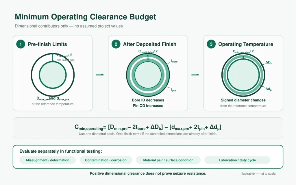
Cالدقائق، التشغيل = [دmin،pre − 2 طنثقب + ΔDb] − [دmax،pre + 2 طندبوس + Δdp]
Dmin،pre و dmax،pre هي حدود القطر قبل التشطيب عند درجة الحرارة المرجعية. ΔDb وΔdp تُعبَّر عنها بتغيرات قطرية موقعة في قطر التجويف والمسمار انطلاقًا من تلك الدرجة الحرارة. إذا كانت الأبعاد المحددة سارية بالفعل بعد التشطيب، فاستبعد مصطلحات التشطيب بدلاً من طرحها مرتين.
يجب استبعاد التشوه، واختلال المحاذاة، والتلوث من هذه المعادلة القياسية ما لم يكن لدى المشروع طريقة معتمدة لتحويلها إلى نفس أساس الفراغ. فقد تؤدي هذه التأثيرات إلى حدوث تلامس موضعي بدلاً من تغير موحد في القطر، كما أن التلوث لا يُعتبر هامشًا حتميًا ما لم يتم التحكم في حجم الجسيمات ومسار دخولها وحالة التنظيف ومستوى التعرض. استخدم الحساب لتحديد الحدود الأبعادية. استخدم الاختبار الوظيفي لإثبات الحركة في ظل ظروف التشغيل المجمعة.
من الناحية العامة، ضع ميزانية موازية للعب الحر في بداية العمر التشغيلي ونهايته. عادةً ما يؤدي التآكل إلى زيادة الخلوص، لكن حطام التآكل أو المواد المنقولة أو نواتج التآكل أو البطانة التالفة قد تزيد من الاحتكاك في الوقت نفسه. إذا كان التعرض للتآكل جزءًا من ظروف التشغيل، فحدد معنى هذا التعرض ومعايير القبول؛ الحالية معايير اختبار رش الملح للمفصلات تفصل هذه الصفحة بين ظروف الغرفة وحدود الحركة والتآكل بعد الاختبار.
لماذا لا يوجد رقم تخليص جمركي موحد؟
فالمفصلة الصغيرة للأجهزة، وباب المعدات الملحوم، ولوحة الوصول الخارجية المتسخة لا تشترك في قطر الدبوس نفسه، أو طول المحمل، أو عملية التصنيع، أو الحمل، أو نطاق الحركة المسموح به، أو نطاق درجة الحرارة، أو مستوى التلوث. فإن استخدام فجوة ثابتة موحدة في جميع هذه المنتجات قد يكون مكلفًا بشكل غير ضروري في أحدها وغير موثوق به في آخر. وحتى نسبة الفجوة إلى القطر تتجاهل طول المحمل، والمحاذاة، والتشطيب، وزوج المواد، والتشحيم، وحد الحركة الوظيفية.
الرقم القابل للتبرير هو النطاق الذي يتجاوز الحد الأقصى للانحراف في الجانب الضيق للمشروع، ويبقى دون الحد الأقصى للحركة في الجانب الفضفاض، ويمكن إنتاجه وفحصه باستخدام العمليات المختارة.
ضع «الملاءمة الوظيفية» على الرسم
لا يكفي ذكر القيمة الاسمية للمسمار، وكتلة التفاوت العامة، وملاحظة المواد. فالمورد بحاجة إلى معرفة أي تجويف يتحكم في الدوران، ومتى تنطبق الأبعاد، وأي حالة نهائية يجب أن تكون متحركة. ضع قسم المسمار والمفصل، ونظام الإحداثيات، وحدود التشطيب، وصيغة القبول في تعريف المنتج الخاضع للرقابة. الأوسع نطاقاً ورقة مواصفات المفصلات ودليل الرسومات يشرح كيف تتكامل هذه التفاصيل مع مجموعة الرسومات الكاملة.
| حقل الرسم أو المواصفات | ما الذي يجب ذكره | لماذا يؤثر ذلك على النتيجة؟ |
|---|---|---|
| واجهة دوارة | منطقة التثبيت ومفصل التوصيل أو القطر الداخلي للجلبة المركبة، بما في ذلك طول المحمل المحوري | يمنع تطبيق علامة «ملاءمة الحركة» على منطقة ثابتة من حيث الدوران |
| حدود الحجم | حدد القيم القصوى للقطر الخارجي (OD) والقطر الداخلي الوظيفي (ID)، أو حدد تصنيف التوافق المناسب مع القيم القصوى | يحدد الحد الأدنى والحد الأقصى للفراغ التصنيعي |
| أساس التخفيض | قطري أو شعاعي؛ بداية العمر التشغيلي، وعند الضرورة، نهاية العمر التشغيلي | يمنع حدوث خطأ في التفسير بنسبة اثنين إلى واحد |
| شرط البعد | قبل أو بعد التشطيب، قبل أو بعد تركيب البطانات، ودرجة الحرارة المرجعية | يربط قيم الفحص بسطح الدوران الفعلي |
| عناصر التحكم الهندسية | معايير ومراجع الموضع، والاستقامة، والاستدارة، والانحراف، أو التوازي المحوري للمحاور ذات الصلة | يحد من التلامس المحلي الذي لا يمكن للقطر وحده منعه |
| حدود التشطيب | المواد، والتشطيب، والتغطية، والتراكم المسموح به على أسطح الدبوس والتجويف | يحافظ على الفجوة النهائية المقصودة |
| حالة التشغيل | نطاق درجة الحرارة، أو الحمل أو الاتجاه، أو حالة مادة التشحيم، أو التلوث، أو حدود التعرض | يحدد الحالة التي يجب أن يظل فيها الدوران حرًا |
| القبول الوظيفي | حد قوة التشغيل أو حد عزم الدوران، وحد اللعب الحر، وزاوية الاختبار، والاتجاه، ونقطة الإسناد، ونقطة القياس | يتحقق من السلوك الذي تهدف الأبعاد إلى حمايته |
نموذج مواصفات الرسم
يوضح الهيكل التالي الحقول التي تحتاج إلى قيم. ولا يُعتبر هذا المطلب مكتملًا إلا بعد أن يقوم المشروع باستبدال كل عنصر موجود بين قوسين ببيانات معتمدة.
واجهة التشغيل: قم بتوصيل منطقة الدبوس [المعرّف] بالفتحة/الجلبة المركبة [المعرّف].
قم بتعيين OD بعد [FINISH/PROCESS]: من [dMIN] إلى [dMAX].
القطر الداخلي التشغيلي بعد [عملية التشطيب/التركيب]: من [DMIN] إلى [DMAX].
الخلوص القطري الناتج عند [درجة الحرارة المرجعية]: من [CMIN] إلى [CMAX].
يجب أن تدور المفصلة عبر [نطاق الزاوية] دون أي انحشار عند [درجة الحرارة / الحمل / الاتجاه / الحالة]. ويجب ألا تتجاوز [القوة أو عزم الدوران] التشغيلية [الحد الأقصى] باستخدام [طريقة الاختبار]. إذا كان التآكل أو التلف الناتج عن الانغلاق يمثل مصدر قلق في المشروع، فيجب أن تستوفي الأسطح بعد الاختبار [معايير التآكل / الخدش المحددة] بعد [الحمل المحدد].
يجب ألا يتجاوز «اللعب الحر للتجميع عند [زاوية المفصلة]، المقاس بين [نقطة مرجعية ثابتة] و[هدف متحرك] تحت حمل مسبار يبلغ ±[حمل المسبار]،» القيمة [الحد].
لا تدرج أرقامًا متضاربة في الرسم ومواصفات الشراء وخطة الفحص. إذا كان الرسم هو المرجع المرجعي لأبعاد المكونات، وكانت مواصفات الاختبار المنفصلة هي المرجع المرجعي لحركة المكونات بعد التجميع، فيجب الإشارة إلى الوثيقة ورقم المراجعة.
افحص الأبعاد والحركة
يحدد الفحص الأبعادي ما إذا كانت القطع الموردة تتوافق مع مجموعة الفراغات المحددة. أما الفحص الوظيفي فيحدد ما إذا كانت المفصلة المكتملة تتحرك وتبقى ضمن حدود اللعب الحر المسموح به. وكلاهما ضروريان عندما يتأثر التوافق بالشكل الهندسي الناتج عن التشكيل، أو الضغط، أو التشطيب، أو التثبيت، أو التركيب، أو التعرض للعوامل البيئية.
الأدلة المتعلقة بالأبعاد
قم بقياس الدبوس عبر عدد كافٍ من المواقع الزاوية والمحورية للكشف عن أي انحراف أو تشوه أو تراكم موضعي أو تلف يتعلق بمنطقة المحمل. قم بقياس التجويف التشغيلي أو القطر الداخلي للجلبة المركبة في المواقع والاتجاهات التي قد تصبح ضيقة. يجب أن تتناسب الأداة مع التفاوت المسموح به والسطح. يمكن لمقياس السدادة فحص الحد بكفاءة، في حين أن مقياس التجويف أو أي أداة قياس داخلية مناسبة يمكنها توفير معلومات عن الحجم الفعلي والشكل الجانبي. قم بتسجيل ما إذا كانت النتيجة قبل أو بعد التشطيب والتركيب.
لا تحسب الخلوص بطرح متوسطات غير ذات صلة. قم بمقارنة الأبعاد الحدية الفعلية أو قم بتقييم الحدود المحددة للمجموعة. فقد يبدو متوسط قطر الدبوس ومتوسط قطر التجويف مناسبين، في حين أن تركيبات الأطراف قد تؤدي إلى حدوث تداخل أو ارتخاء مفرط.
أدلة الحركة الوظيفية
قم بتشغيل المفصلة عبر الزاوية المطلوبة في اتجاهها المحدد. حدد السرعة، والحمل المطبق، ودرجة الحرارة، وظروف التشغيل، وحالة مادة التشحيم، وما إذا كانت القوة المبلغ عنها هي قوة الانفصال أم قوة التشغيل. يعتمد الفحص البسيط بنظام “النجاح/الفشل” الذي يتم «بالحركة اليدوية» على المشغل وقد يخفي وجود احتكاك عالٍ. يمكن أن تكشف بيانات «القوة مقابل الزاوية» أو «عزم الدوران مقابل الزاوية» عن انحشار موضعي قد تفوته القراءة القصوى الواحدة.
قم بقياس اللعب الحر في الحالة التي يؤثر فيها على الأداء الوظيفي: زاوية الفتح، أو وضع الإغلاق، أو وضع الصيانة، أو أي نقطة محددة أخرى. استخدم حملًا متكررًا إيجابيًا وسلبيًا للمسبار يملأ الفجوات دون إحداث تشوه متعمد في المجموعة. قم بالإبلاغ عن نقطة القياس ونصف القطر في حالة استخدام الإزاحة بدلاً من الزاوية.
أدلة الإفراج عن هذا التوافق:
- يُظهر المقطع العرضي كل منطقة دوارة، ومنطقة ثابتة بالنسبة للدوران، وسمات التثبيت المحوري.
- تحدد حدود الدبوس والفتحة الوظيفية الحد الأدنى والحد الأقصى المعتمدين للخلوص القطري.
- تشمل شروط الأبعاد حالة التشطيب، وتركيب البطانات، والتثبيت بالأوتاد، ودرجة الحرارة المرجعية.
- يشمل تحليل الجانب الضيق حدود المشروع من حيث التشطيب، والخصائص الحرارية، والتشوه، والمحاذاة، والتلوث.
- يتضمن تحليل الجانب المرن فترة التشغيل الأولية وفترة التشغيل الحر المطلوبة بعد انتهاء الخدمة.
- يحدد الاختبار الوظيفي الزاوية، والاتجاه، ونقطة الإسناد، والحمل، والسرعة، ودرجة الحرارة، وحدود القبول.
- تمثل عينات الأدلة المواد النهائية والعمليات وهندسة التركيب.
إذا تعذر على قسم الإنتاج قياس إحدى الخصائص الداخلية المركبة بشكل مباشر، فيجب وضع معيار مراقبة مرتبط بالمكونات أو معلمات العملية، والتحقق دوريًّا من التجميع النهائي. ويجب أن تستند هذه الارتباطية إلى بيانات دراسية فعلية، ولا يجوز افتراضها استنادًا إلى الأبعاد الاسمية.
إرسال قسم «الدبوس والمفصل»
لإجراء مناقشة مفيدة حول المفصلات، يجب تضمين المقطع العرضي، وحدود المسامير والتجاويف، ومناطق الدوران، والمناطق الثابتة دورانيًّا، والاحتفاظ المحوري، والمواد، والتشطيبات، ودرجة حرارة التشغيل، واتجاه الحمل، والخلوص المطلوب، وأي ظروف لاحقة للتعرض. تتيح هذه المدخلات مراجعة حدود الملاءمة دون الاعتماد على التخمين في تحديد خلوص عام.
الأسئلة الشائعة حول الفراغ بين مسمار المفصلة
هل يجب أن يكون الفراغ بين مسمار المفصلة صفرًا؟
لا ينطبق ذلك على الواجهة التي تدور بحرية، ما لم يستخدم التصميم مبدأً آخرً من مبادئ المرونة أو المحامل. فالخلوص الاسمي الصفري لا يترك أي هامش لتباين الأحجام، أو تراكم الطلاء، أو الفروق الحرارية، أو الأخطاء الهندسية، أو التلوث. وقد تستخدم المنطقة الثابتة دورانيًّا أو المثبتة بالضغط مبدأ التداخل، لكن يجب تحديدها بشكل منفصل عن مناطق التشغيل والاحتفاظ المحوري.
ما الفرق بين الفراغ المحوري والفراغ القطري لمسمار المفصلة؟
الخلوص القطري هو القطر الداخلي للفتحة مطروحًا منه القطر الخارجي للمسمار. أما الخلوص الشعاعي فهو نصف هذا الفرق بالنسبة للأجزاء الدائرية المحورية المثالية. وينبغي أن يحدد كل من المواصفات والتقرير الأساس الذي تم استخدامه.
هل يعتبر التوافق H7/g6 مناسبًا دائمًا لمسمار المفصلة؟
لا. ففئة الملاءمة تحدد نطاقات التفاوت في الحجم، ولا تحدد التلاعب الحر المقبول للمفصلة، أو تراكم الطلاء، أو الهندسة التثبيتية، أو درجة الحرارة، أو التلوث، أو طول المحمل. لا تستخدم فئة الملاءمة إلا بعد تحديد الحدود الدنيا والقصوى للفراغ التشغيلي للمشروع.
هل ينبغي قياس الفراغ بين مسمار المفصلة قبل الطلاء أم بعده؟
يجب التحقق من الملاءمة الوظيفية في الظروف التي تحد من الدوران. إذا وصل الطلاء أو أي تشطيب آخر إلى الدبوس أو التجويف، فيجب استخدام الأبعاد النهائية بعد ذلك التشطيب، أو احتساب السماكة الكاملة المسموح بها ضمن حدود ما قبل التشطيب. يجب ذكر ظروف القياس في الرسم.
كيف يتم فحص اللعب الحر لمسمار المفصلة؟
يمكن حساب الخلوص بين المكونات استنادًا إلى القطر الخارجي المقاس للسن والقطر الداخلي الوظيفي للتجويف. ويتطلب اللعب الحر للتجميع إجراء فحص حركة منفصل باستخدام نقطة مرجعية ثابتة محددة، وهدف متحرك، وزاوية مفصلية، وحمل إيجابي وسلبي للمسبار، وحد زاوي أو خطي. قم بتسجيل نصف قطر القياس عند الإبلاغ عن الإزاحة الخطية.