-
+86 13720060320
-
lanna@haitangs.com

ヒンジの軸方向遊び:軸方向の動き、スラスト制御および測定
ヒンジは自由に回転し、ピン径の検査に合格していても、図面では想定されていない方向に動くことがあります。片方の葉をピンの軸に沿って押し、引き戻すと、組み立て部品から小さなカチッという音や、測定可能なずれが生じることがあります。その動きは ヒンジの軸方向遊び.
従来のピン・ナックル式ヒンジでは、通常、わずかな軸方向の遊びが設けられており、これにより隣接するナックルやスラスト界面が引っ掛かることなく回転できるようになっています。精密ヒンジや予圧がかけられたヒンジの構造では、この動きの制御方法が異なる場合があるため、許容されるエンドプレイは、一律に「遊びゼロ」というルールではなく、実際の設計に基づいて決定する必要があります。.
軸方向の動きが大きすぎると、ドアの位置がずれたり、スラスト面間で繰り返しの衝撃が生じたり、止め金の噛み合わせが変化したり、騒音が増大したり、あるいは本来は堅固なパネルが緩んだように感じられたりすることがあります。一方、動きを完全に排除しようとすると、逆の問題が生じます。 製造公差、コーティングの堆積、成形誤差、熱膨張、スラストワッシャーの厚さ、あるいは位置ずれした保持部などが、意図されたクリアランスを埋めてしまい、ピボットを軸方向のクランプに変えてしまうことがあります。.
実用的な定義: ヒンジのエンドプレイとは、ヒンジピン軸に沿ってヒンジ葉または回転アセンブリが生じる相対的な動きのことです。有用な仕様書では、何が固定され、何が可動であるか、どの程度の軸方向の力が加えられるか、変位がどこで測定されるか、および試験中のヒンジの状態についても定義されています。.
エンドプレイは半径方向ではなく軸方向である
エンドプレイは、作業者がこれらすべてを「遊び」と表現することがあるため、他の形態のヒンジの緩みとひとまとめにされることがよくあります。しかし、この表現は、図面や検査要件としてはあまりにも広義すぎます。.
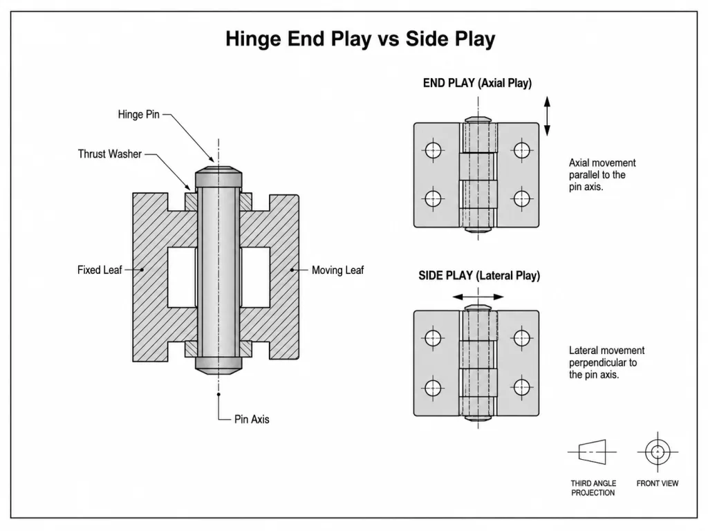
| 動き | 方向または状態 | 内容について | 一次制御 |
|---|---|---|---|
| エンドプレイ | ヒンジピンの軸と平行に | ヒンジ葉または回転部品間の相対的な軸方向の動き | 軸方向の積層、スラスト面、ワッシャー、肩部、スペーサー、および保持機構 |
| サイドプレイ | ピン軸に対して垂直 | ヒンジ葉間の相対的な横方向の動き | ピンと穴のクリアランス、ベアリングの長さ、ナックルの形状、および組み立て状態 |
| ピンのクリアランス | 回転するピンと穴の接合部において | ピンの外径と機能孔の内径との寸法差 | ピンおよび穴の寸法限界、表面仕上げ、温度、および嵌合 |
| 組み立て不要で遊べる | ドアまたはパネルで測定 | 参加しているすべてのインターフェースにおける可視的な緩みの合計 | 組立試験の完了 |
| トルクヒンジのバックラッシュ | 回転を逆転させた後 | 出力が反応するまでのAngularの遅延 | トルク機構および角度試験方法 |
| リフトオフ・クリアランス | 取り外し時の意図的な軸方向の移動 | 着脱式ヒンジを外すのに必要な距離 | ピンの嵌合およびドア取り外し範囲 |
ピンのクリアランスと横方向の遊びは関連していますが、同じパラメータではありません。 ピンと穴のクリアランスは、ピボット内部の寸法条件を指します。横遊びとは、組み立てられたヒンジ部品間で観察される、その結果として生じる横方向の動きのことです。ナックルの長さ、ベアリングのスパン、局所的な摩耗、位置合わせ、および力が加わる位置によって、ピンと穴の寸法が変化していなくても、測定される横遊びは変化する可能性があります。.
したがって、ヒンジには許容範囲内の半径方向の作動クリアランスがあっても、組み立てられたヒンジには依然として過大な軸方向のエンドプレイが残っている場合があります。その逆のケースも起こり得ます。つまり、軸方向の動きは厳密に制御されているにもかかわらず、過大な半径方向のクリアランスやベアリング接触面の摩耗によって、ヒンジ葉の横方向の動きが生じる場合があります。.
ピボット内部への寸法適合については、以下の ヒンジピンのクリアランスガイド. 。そのページでは、ピンおよび穴の寸法限界、仕上げによる肉盛り、作動クリアランス、遊ひ、および固着のリスクについて解説しています。ヒンジのエンドプレイについては、別途軸方向の要件が必要です。.
軸方向の動きの発生原因
隣接する2つのナックルの間に目に見える隙間がある場合、エンドプレイの原因となる可能性がありますが、それが原因でスタック全体がずれることはめったにありません。.
産業用ヒンジには、複数の軸方向の接合部が直列に配置されている場合があります。可動アセンブリがピンの一方の端からもう一方の端に向かって押されると、各接合部が総移動量の一部を担うことがあります。.
- 隣接するナックルの端面間のクリアランス;;
- スラストワッシャーの厚さと圧縮量;;
- ワッシャーと保持肩との間のクリアランス;;
- ピンが保持部内で軸方向に移動すること;;
- ブッシングとそのハウジングの間に浮いた状態で;;
- スペーサーまたはシムのバリエーション;;
- 成形、ステーキング、スエージング、またはヘッディングのバリエーション;;
- 保持リングの溝の位置;;
- 荷重がかかったスラスト面での摩耗;;
- 薄いクリップや支持部材の弾性的な動き。.
これは、図面が1つの明らかな寸法のみを規定している場合に重要となります。ナックル端部の公称クリアランスがあっても、組み立てられたヒンジに同じ量のエンドプレイがあるとは限りません。ワッシャー、フローティングブッシング、ピンリテーナー、スペーサー、または成形された形状などが、軸方向の積層構造の他の箇所に動きを生じさせる可能性があります。.
その逆のケースも考えられます。図面上ではいくつかの名目上のクリアランスに余裕があるように見えても、1枚のワッシャーが歪んでいたり、端面が斜めになっていたりすると、それが先に接触してしまい、スタック全体が動けなくなることがあります。寸法解析により、利用可能な軸方向の許容範囲が予測されます。完成したヒンジによって、その許容範囲のうち実際に機能する部分がどれほどあるかが確認できます。.
軸方向の荷重にはスラスト経路が必要
「エンドプレイ」とは動きのことを指します。軸方向の荷重によって、その動きを止める面が決まります。.
垂直に側方ヒンジが取り付けられたドアの場合、重力および取り付け形状により、ヒンジスタックの一部が下側のナックル端、ワッシャー、肩部、フランジ、または支持面に密着することがあります。ヒンジ軸が水平または傾斜している場合、有効な推力の方向は異なる可能性があります。 また、輸送時の加速度、振動、ばね力、操作者による荷重、ケーブルの引っ張り力、またはラッチの動作によっても、一時的な軸方向の反力が生じることがあります。.
について ヒンジの応用工学 したがって、審査ではスラスト伝達経路を特定する必要があります。スリーブブッシングの端部が自動的にスラスト軸受になるとは想定しないでください。ラジアル方向の投影圧力下で良好な性能を発揮するブッシングであっても、その端面に繰り返しかかる軸方向の荷重に耐えるよう設計されていない場合があります。.
成形されたナックルについても同様の注意点が当てはまります。薄いロールエッジは、軽負荷下では許容できる幾何学的ストッパーとなるかもしれませんが、より重い可動アセンブリが繰り返しそれに当接する場合、長期的には不適切なスラスト面となります。.
この断面図は、次のように読み取ってください: 可動アセンブリをピンの両端に向かって押し込み、それが停止する正確な面を特定してください。荷重経路が、定義されていないワッシャーの縁、支持されていないポリマー面、クリップ、または成形ナックルで終了している場合、図面ではスラスト界面を制御せずに隙間のみを規定している可能性があります。.
すべり軸受式のピボットについては、 産業用ヒンジブッシングガイド ここでは、ラジアル荷重、ブッシングの材質、潤滑、ハウジングの嵌合、および軸方向荷重に対してフランジ、スラストワッシャー、肩部、あるいは独立した支持が必要となる理由について解説します。このページでは、その内容に続き、その結果生じる軸方向の変位に焦点を当てます。.
エンドプレイが少なすぎる、あるいは多すぎる
“「可能な限り最小のエンドプレイ」というのは、正確に聞こえます。しかし、実際には不完全な要件である可能性があります。.
回転スタックが2つの軸方向の面によってほぼ挟み込まれる場合、通常の製造上のばらつきによって、ヒンジが「フリーランニング」状態から「プリロード」状態へと変化することがあります。仕上げ厚さ、ワッシャーのばらつき、成形位置、バリ、ステーキングによる歪み、あるいは温度などの要因により、残りの余裕が失われる可能性があります。.
ヒンジは、手による点検中に依然として動くことがあるものの、一方の推力面がすでに継続的な圧縮を受けているため、より高い離脱力、温度に依存する摩擦、あるいは局所的な傷が見られる場合があります。.
エンドプレイが大きすぎると、逆方向の故障経路が生じます。可動アセンブリは、反対側のスラスト面に達する前に、許容される軸方向の隙間を移動します。軸方向の荷重が繰り返し反転すると、接触は定常的な軸受反力ではなく、衝撃的な接触となる可能性があります。.
| 状態 | 考えられる証拠 | 次の工学に関する質問 |
|---|---|---|
| エンドプレイが小さすぎる | 摩擦が大きい、断続的な固着、研磨されたスラスト面、温度に敏感な動き | 許容値、仕上げ、歪み、あるいは予圧によって、動作余裕が失われてしまったのでしょうか? |
| エンドプレイが大きすぎる | 軸方向のクリック音、葉のずれが目立つ、衝撃痕、ドアの位置がずれる | どのインターフェースが移動距離の大部分を占めているのでしょうか? |
| 負荷の増加に伴い、エンドプレイも増大する | ワッシャーの摩耗、傷、リテーナーのずれ、スペーサーの変形 | スラストインターフェースが摩耗しているのか、それとも保持部の形状がずれているのか? |
| 動きは向きによって変化する | 組み立て後に回転させたり上下を反転させたりすると、軸方向の位置が異なる | どのスラスト面に重力荷重が作用していますか? |
| ヒンジのわずかな動きが、システム全体に大きな影響をもたらす | ラッチの位置合わせまたはドアの高さの変更 | その装置は、ヒンジ軸のずれを増幅させているのでしょうか? |
産業用ヒンジにおいて、普遍的に正しいエンドプレイの値というものは存在しません。コンパクトな機器の蓋、重量のある筐体の扉、レールのアクセスパネル、および精密なデテント機構では、たとえヒンジピンが類似していても、必要な許容範囲が大きく異なる場合があります。.
軸方向公差の積み重ね
剛性があり、予荷重のない軸方向の積層構造の場合、有用な一次計算として、制御拘束間の利用可能な距離と、その距離を占める構成要素とを区別する。.
一次軸方向の関係
E = A − S
E = 算出された幾何学的エンドプレイ許容値
A = 制御用軸方向拘束面間の利用可能な距離
S = それらの面間の占有スタックの合計
最悪のケースを想定した寸法確認については:
Emin = Amin − Smax
Emax = Amax − Smin
これは寸法上の許容範囲であり、完成したヒンジが計算された量と正確に同じだけ動くことを保証するものではありません。これは、選択された拘束面が実際に機能的な軸方向のストッパーとして作用すること、および予圧、ばね要素、弾性ワッシャー、変形、摩擦、リテーナーの動き、バリ、測定力が応答に影響を与えないことを前提としています。.
軸方向の予圧や調整可能なスラスト機能を意図的に採用したヒンジの場合、幾何学的スタックは依然として重要ですが、測定されたエンドプレイは、A − S のみからではなく、実際の機構および試験条件に基づいて決定する必要があります。.
スタックには、単なる部品の公称値だけでなく、最終的な機能寸法を使用する必要があります。アーキテクチャによっては、これには以下が含まれる場合があります:
- ナックルの長さ;;
- ワッシャーおよびスペーサーの厚さ;;
- ブッシングの取り付け位置;;
- 肩の位置;;
- 襟の厚さ;;
- 保持リングの溝の位置;;
- 形成された、または先端が突出したピン端の位置;;
- 軸方向の接触面におけるコーティング;;
- 杭打ち、圧着、スエージ加工、または成形後の設置寸法。.
最悪の組み合わせが問題となります。個々のコンポーネントはそれぞれ検査に合格していても、組み立てた状態では想定された動作範囲外になってしまうことがあります。.
部品は問題なく通過しても、ヒンジが引っかかることがあります。. 公称のナックルとワッシャーの積層により、わずかな軸方向の動作クリアランスが生じるヒンジを考えてみましょう。個々の部品はいずれも寸法公差を満たしています。 仕上げ加工後、一方のスラスト面がわずかに厚くなり、成形されたリテーナーが回転するスタックに近づいてしまった。ヒンジは依然として組み立て可能だが、軸方向のクリアランスは事実上なくなり、動きにばらつきが生じる。ワッシャーを取り外すと自由な動きは回復するが、過度のエンドプレイが生じる。この技術的な問題は、個別の寸法ではなく、軸方向のスタック全体にあるのである。.
これはあくまで例示的なエンジニアリングシナリオであり、顧客プロジェクトの実績や製品試験の結果を示すものではありません。.
動きを制御するスラスト機能
軸方向の動きを制御できるヒンジの構造にはいくつかの種類があります。これらは、摩耗特性、保守性、製造上の難易度において、それぞれ異なります。.
- ナックルの端面: コンパクトでシンプルですが、成形された端部は軸方向のストッパーとなる一方で、摩耗が生じやすい部分にもなります。.
- スラストワッシャー: 回転する端面との間に意図的な接合部を設けることで、ヒンジのナックル部分への摩耗を隔離することができます。.
- フランジ付きブッシング: スラスト荷重に対応するように正確に設計された構造の場合、ラジアル支持とアキシャル接触を組み合わせることがある。.
- 肩と襟: より明確な軸方向の基準面を形成し、薄肉成形されたナックルのエッジからスラストを遠ざけることができます。.
- スペーサーとシム: スタックの調整は可能とするが、厚みと保持力の制御が必要である。.
- 止め輪およびクリップ: 溝の位置、軸方向のクリアランス、アクセス、および取り付け方向が定義された場合の制御ピンの位置。.
- 突き出し加工、旋削加工、成形加工、またはヘッディング加工が施されたピンの端部: コンパクトな保持力を確保できますが、最終的な軸方向の位置は成形プロセスに大きく左右される場合があります。.
スラスト用部品は、その名称だけで選定すべきではありません。ワッシャーは寸法的に正確であっても、かかる荷重に対して材質が柔らかすぎたり、支持が不十分だったり、汚染されていたり、あるいは粗い成形エッジと接触して回転したりすると、急速に摩耗する可能性があります。一方、硬い金属製の組み合わせは形状を維持できるかもしれませんが、摩擦の増加、スコーリング、騒音、あるいは潤滑剤への依存度を高める原因となる場合があります。.
エンドプレイに関する要件は、必ずしも独立した材料に関する項目とする必要はありません。ただし、どの部材が推力を受け持ち、その部材が要求される使用条件下において、意図された軸方向の動きを維持できるかどうかを特定する必要があります。.
個々の隙間ではなく、アセンブリ全体を測定する
隙間ゲージを使用すると、2つの表面間の測定可能な局所的な隙間を確認できます。この測定値は、図面でその正確な隙間が規定されている場合に役立ちます。ただし、この値が必ずしも機能的なヒンジの遊びに等しいとは限りません。.
完全なエンドプレイ試験では、アセンブリの一部を固定し、可動側に両軸方向から荷重を加え、その結果生じるヒンジピン軸に沿った変位を記録します。.
- 固定基準点を設定する。. 設置時の基準となるヒンジリーフ、取り付けプレート、ハウジング、または固定具の表面を使用してください。.
- 動く標的を選んでください。. そのインジケーターが、対向するリーフ、ナックルスタック、ピン、あるいはその他の制御面を追跡するかどうかを明記してください。.
- 測定軸をヒンジピンの軸と合わせてください。. センサーがピンの軸と平行でない場合、表示される変位量は直接的な軸方向の測定値ではなく、また、横方向や回転方向の動きの影響を受けやすくなる可能性があります。.
- アセンブリを軸方向の1方向にセットしてください。. 衝撃を与えずに所定の力を加え、その位置を記録する。.
- 軸方向の荷重を逆転させる。. 反対側のスラストインターフェースが確実に嵌合するまで、アセンブリを移動させてください。.
- 総変位量を記録してください。. これら2つの制御位置の違いは、その試験条件下で測定されたエンドプレイの値である。.
ダイヤルゲージ、デジタル変位プローブ、コンパレータ、高さゲージ、あるいは専用の生産用治具のいずれも有効です。重要な要素としては、基準点、力、方向、センサーの位置合わせ、測定器の分解能、治具の剛性、および再現性が挙げられます。.
フィクスチャの負荷および測定条件
荷重のかかり方が明記されていないエンドプレイの数値は、誤解を招く恐れがあります。保持クリップ、ポリマーワッシャー、薄いブラケット、あるいはドア全体は、加わる軸方向の力が変化すると、それぞれ異なるたわみ方をすることがあります。.
| テストフィールド | なぜ重要なのか | 要件 |
|---|---|---|
| 固定基準点 | 結果からどのモーションを除外するかを決定します | リーフ、ブラケット、ハウジング、またはフィクスチャのどの表面であるかを正確に指定してください |
| 動く標的 | 葉の動きとピンの動きを分離する | 測定対象の表面またはターゲットに名前を付けてください |
| 軸方向のプローブ荷重 | 負荷が異なると、フレキシブルインターフェースの嵌合状態も異なってくる | 大きさと方向を定義する |
| ヒンジの角度 | デザインによっては、角度によって座り心地が異なるものもあります | 必要な試験角度を指定してください |
| オリエンテーション | 重力は、1つの推力面に対して予荷重をかけることができる | 垂直、水平、傾斜、または設置時の向きを指定する |
| 温度 | 材質や潤滑状態は、嵌合や着座に影響を与える可能性があります | 必要に応じて、参照状態または条件付き状態を定義する |
| 測定方法 | 試合日程の変更が記録に反映される | センサーの位置、位置合わせ、分解能、およびゼロ点設定手順を定義する |
| 許容範囲 | 観測データを生産要件に変換する | 最大エンドプレイ、および必要に応じて最小エンドプレイ |
探針の加える力は、チェックを単なる変形試験に変えてしまうことなく、対象の推力面を確実に密着させるのに十分なものでなければなりません。コンパクトなヒンジに適した力が、別の設計の葉板やブラケットを曲げてしまう可能性があります。したがって、その値は、普遍的なルールから導き出すのではなく、実際の組立状態と再現性試験に基づいて決定する必要があります。.
向きも重要な要素です。垂直ヒンジで吊り下げられた重い扉は、試験荷重が加えられる前から、すでに一方の押し当て面に密着している可能性があります。一方、水平方向に試験された小型のベンチヒンジは、両方の押し当て面の間に浮いた状態になることがあります。試験方法においてこの違いが考慮されていない限り、これら2つの条件における試験結果を直接比較することはできません。.
ピンの動きと葉の動きは異なる
軸方向のインジケーターの測定値だけでは、ヒンジのどの部分が動いたのかは自動的に判断できません。.
保持部内で意図的または意図せずに自由に動くピンは、2枚のリーフが同じスラスト接触面に密着したままであっても、位置がずれる可能性があります。したがって、ピンのみを測定した場合、装置で観測されるリーフ間のエンドプレイとは異なる動きが検出される可能性があります。.
その逆のケースも起こり得ます。しっかりと固定されたピンは、可動式のナックルスタックが2つの肩部またはワッシャーの間を移動している間も、その位置に留まったままになることがあります。.
両方の機能が重要な場合は、それぞれ個別に制御してください:
- ピンの軸方向の動き: ピンを保持することを目的としたリーフまたは本体に対するピンの相対的な動き。.
- ヒンジの軸方向遊び: 可動ヒンジアセンブリが、ヒンジピン軸に沿って固定アセンブリに対して行う動き。.
これら2つを1つの定義されていない「軸方向の遊び」という値にまとめると、実際の故障メカニズムが見えにくくなる可能性があります。保持部の緩みとスラストワッシャーの摩耗では、インジケーターの総移動量は類似していても、必要な是正措置は異なります。.
摩耗、温度、および点検・整備
初日のエンドプレイは、ヒンジに繰り返しスラスト荷重がかかる場合の初期条件に過ぎない。.
ナックルの端面は、研磨されたり摩耗したりすることがあります。スラストワッシャーの厚みが薄くなる場合があります。ポリマー製部品は、材質や状態によっては、持続的な荷重がかかるとクリープ現象を起こすことがあります。リテーナーは、その嵌合位置が変化しても取り付いたままになることがあります。スペーサーは、隣接する表面に対してフリート現象を起こすことがあります。こうした変化のそれぞれが、軸方向の積層構造に影響を与えます。.
温度もまた、もう一つの変数となります。材料や部品の温度が異なると、ショルダー、ワッシャー、ブッシュ、および保持部間の有効距離が変化する可能性があります。その結果、軸方向の移動量が増加したり減少したりする可能性があります。.
温度差だけが温度に関する問題のすべてではありません。低温では正の軸方向クリアランスが生じる一方で、潤滑剤やポリマーの挙動によって運転時の摩擦が増加することがあります。高温では、材料の膨張、クリープ、あるいは潤滑剤の移動によって、座面接触状態と摩耗挙動の両方が変化する可能性があります。.
したがって、エンドプレイの要件では、その限界値が適用される条件を明確に定める必要があります。機器によっては、室温での受入検査のみで十分な場合もあります。一方、設計によっては、サイクル試験、温度調整、振動試験、洗浄、腐食暴露、あるいはその他の代表的な使用条件を経た後に、同様の測定が必要となる場合もあります。.
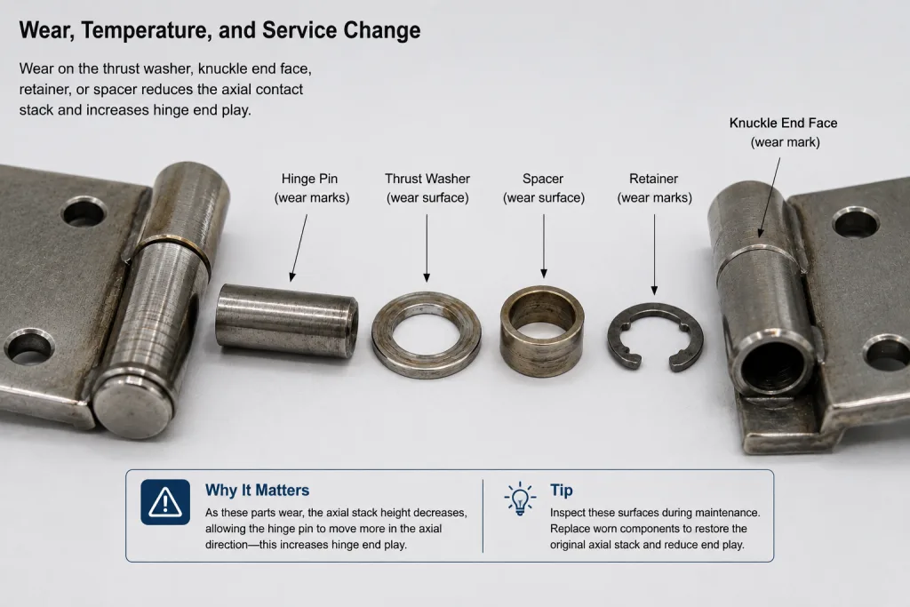
整備後にエンドプレイが増加した場合は、最終的な変位量だけでなく、それ以前の値も記録してください。スラスト面、ワッシャーの厚さ、ピンの端部、リテーナーの位置、ブッシングの嵌合状態、スペーサー、接触パターン、および異物を点検してください。測定結果から、スタックに変化が生じたことがわかります。こうした物理的な証拠は、変化が生じた箇所を特定するのに役立ちます。.
図面にエンドプレイを指定する
「遊びが最小限」、「ヒンジの遊びが少ない」、「目立った軸方向の動きがない」といった表現は、有用な合格基準とはなりません。.
ヒンジの製造に用いる形状は、部品の寸法に基づいて決定すべきである。エンドプレイが完成品の機能に影響を与える場合は、その結果生じる動きを規定する組み立て要件を別途追加すること。.
要件構造の例 — 角括弧で囲まれた各フィールドを、承認済みのプロジェクトデータに置き換えてください:
[固定基準面/アセンブリ] と [可動葉/ターゲット] 間のヒンジエンドプレイ。ヒンジピン軸に平行な方向で、 [HINGE ANGLE]の角度で[ORIENTATION]の向きに、軸方向荷重+[F]および−[F]が加わった状態で測定されたヒンジのエンドプレイは、[ASSEMBLY / FINISH / CONDITION]の後、[MINIMUM IF REQUIRED]から[MAXIMUM]の範囲内であるものとする。.
PINの軸方向の移動量は、個別に制御される場合、[保持基準点]を基準として[限界値]を超えてはならない。.
[規定の負荷/曝露]の後も、ヒンジのエンドプレイは[許容範囲]内に収まっていなければならず、また、スラスト面および保持面は[規定の機能基準または損傷基準]を満たしていなければならない。.
括弧内の記述は、確定した業界仕様ではありません。担当エンジニアは、実際の機器要件、ヒンジの構造、公差解析、および検証結果に基づき、値を割り当てる必要があります。.
サプライヤーの図面において、ヒンジに適用される寸法、公差、および注記が明確になっていない場合は、 ヒンジの仕様書および設計図面ガイド 名目上の形状と、機能要件および試験に依存する要件とを区別するため。.
生産チェックの相関分析
開発ラボでは、剛性のある治具、制御された軸方向の荷重、および高分解能の変位センサーを用いて、ヒンジのエンドプレイを測定することがあります。しかし、量産時の検査において必ずしも同じ装置が必要というわけではありません。.
実際の相関検証により、適合品と不適合品のヒンジを確実に区別できることが確認された場合は、より簡素なゲージや専用の治具が適している場合があります。ただし、その場合でも、座り込み力の制御、基準面、向き、および設計測定値との既知の関係は確保する必要があります。.
組み立て後のエンドプレイチェックを、1枚のワッシャーやスペーサーの検査だけで代用してはならない。ただし、研究データにより、その部品の寸法が最終的な動きを確実に予測できることが示されている場合はこの限りではない。成形、ピンの保持、取り付け、積層によるばらつき、および局所的な干渉は、いずれも組み立て後の結果に影響を与える可能性がある。.
手による点検は、明らかなガタを見つけるのに役立ちます。ただし、許容される動きが小さく、アライメント、止め位置、騒音、シール性、または機器の操作感に影響を及ぼすような場合には、これだけでは明確なエンドプレイ測定の代わりにはなりません。.
軸方向スタックをレビュー用に送信する
ヒンジの遊びがドアの位置、騒音、軸方向の衝撃、止め金の噛み合わせ、または耐用年数に影響を与える場合は、最終的な要件について協議する前に、ピンおよびナックル部の仕様を策定してください。 その際、固定葉および可動葉、ピンの保持方法、ナックルの長さ、ワッシャーまたはスペーサー、スラスト面、取り付け方向、軸方向荷重の方向、材質、表面仕上げ、および要求される可動条件を含めてください。.
構造用ドア、点検口、キャビネット、および機器筐体については、当社の 産業用ヒンジ製品ラインナップ 利用可能なヒンジの構造や取り付け構成を比較するためです。候補となるヒンジが特定されれば、軸方向の積層やエンドプレイの要件について、製品の外形寸法のみから推測するのではなく、実際の断面図に基づいて確認することができます。.
ヒンジの軸方向遊びに関するよくある質問
ヒンジのエンドプレイとは何ですか?
ヒンジのエンドプレイとは、ヒンジピン軸に沿って、ヒンジの可動部と固定部の間で生じる相対的な軸方向の動きのことです。これは、ピンの半径方向のクリアランスや横方向の遊びとは異なります。有用なエンドプレイの仕様では、固定基準点、可動目標点、軸方向の試験荷重、ヒンジの向き、測定条件、および許容移動量が定義されます。.
ヒンジのエンドプレイとサイドプレイの違いは何ですか?
エンドプレイとは、ヒンジピンの軸に平行な方向への動きのことです。サイドプレイとは、ヒンジピンの軸に垂直な方向におけるヒンジ葉間の相対的な動きのことです。 ピンと穴のクリアランス、ベアリングの長さ、ナックルの形状、摩耗、および組み立て状態はサイドプレイに影響を与える一方、軸方向の隙間、スラスト面、ワッシャー、スペーサー、および保持構造は主にエンドプレイを制御します。.
ヒンジのエンドプレイはゼロであるべきでしょうか?
必ずしもそうとは限りません。 従来のピン・ナックル式ヒンジでは、通常、意図しないスラスト予圧や固着が生じることなく回転できるよう、十分な軸方向の自由度が必要です。精密ヒンジや予圧がかけられたヒンジの設計では、軸方向の動きの制御方法が異なる場合があります。適切な最小値および最大値は、普遍的な「遊びゼロ」というルールではなく、実際のヒンジ構造、公差の積み重ね、動作条件、および機器の要件に基づいて決定されるべきです。.
ヒンジのエンドプレイはどのように測定しますか?
所定のヒンジ基準点を固定し、可動アセンブリ上の所定の点を測定し、ヒンジピン軸に平行な両方向に制御された軸方向の力を加える。2つの着座位置間の変位が、その試験条件下における測定されたエンドプレイである。また、結果に影響を与える場合は、試験において、向き、ヒンジ角度、プローブ力、測定器の分解能、および温度を定義する必要がある。.
なぜ、繰り返し動作を行った後にヒンジの軸方向遊びが大きくなるのでしょうか?
スラストワッシャー、ナックルの端面、スペーサー、肩部、ブッシュ、または保持部が摩耗、変形、クリープ、または位置ずれを起こすと、エンドプレイが増加する可能性があります。 使用後に軸方向の移動量が増加した場合は、その変化量を測定し、スラスト面、リテーナーの位置、ワッシャーの厚さ、ピンの端面、接触痕、および異物を点検して、軸方向の積層構造のどの部分が変化したかを特定してください。.