-
+86 13720060320
-
lanna@haitangs.com

Charnières pour protecteurs de machines et portes d'accès de sécurité
Une charnière montée sur un dispositif de protection d'une machine ou sur une porte d'accès de sécurité ne se contente pas de soutenir un panneau. Elle détermine la manière dont le dispositif de protection pivote, si celui-ci revient à une position fermée reproductible, comment l'écart du côté de la charnière évolue tout au long de l'arc d'ouverture, et si l'affaissement de la porte finit par perturber le fonctionnement du loquet ou de l'actionneur de verrouillage.
La charnière ne constitue pas un dispositif de contrôle de sécurité de la machine. Elle ne peut pas détecter un capot ouvert, arrêter un mouvement dangereux, vérifier que la porte est bien fermée ni empêcher un démarrage intempestif. Ces fonctions relèvent du dispositif de verrouillage et du système de commande de sécurité. Cependant, une charnière mal choisie ou mal montée peut compromettre le comportement mécanique dont dépend l'ensemble du système de protection.
Ce guide explique les exigences spécifiques aux charnières pour les protecteurs de machines, les portes de cellules robotisées, les portes d'accès aux convoyeurs, les enceintes de machines-outils et autres protecteurs mobiles similaires. Il aborde notamment le comportement de fermeture automatique, la force de fermeture, les jeux au niveau de la ligne de charnière, les risques de pincement et de cisaillement, la durée de vie, la résistance au sabotage, le montage sur châssis, l'alignement des verrouillages et la vérification après installation. Pour le choix général d'une gamme de produits, consultez notre guide sur Comment choisir une charnière industrielle.
Front de décision : L'évaluation des risques réalisée par le constructeur de la machine détermine si le dispositif de protection doit être interverrouillé, verrouillé par le dispositif de protection, à fermeture automatique ou contrôlé d'une autre manière. Le fournisseur de charnières peut donner des conseils sur le support mécanique, le mouvement, la retenue, le montage et la durabilité, mais ne doit pas être considéré comme le concepteur de la fonction de contrôle de sécurité de la machine.
C'est la charnière qui est mécanique, et non le dispositif de sécurité
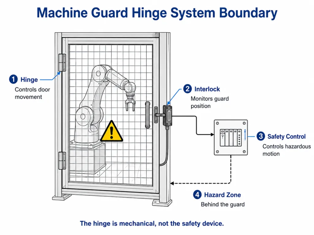
Une charnière de porte de protection soutient la porte et contrôle son mouvement. Selon sa conception, elle peut également assurer une fermeture automatique, une résistance au maintien en position ouverte, une butée définie ou une protection contre tout démontage accidentel. Elle n'assure pas de fonction de contrôle liée à la sécurité.
La norme ISO 14120:2015 traite de la conception générale, de la construction et de la sélection des protecteurs fixes et mobiles. Elle distingue spécifiquement ces exigences relatives à la construction des protecteurs des dispositifs de verrouillage, qui font l'objet de la norme ISO 14119:2024. La norme ISO 14119 couvre la conception et la sélection des dispositifs de verrouillage associés aux protecteurs et inclut des mesures visant à réduire les risques raisonnablement prévisibles de contournement de ces dispositifs.
En ce qui concerne la décision déterminante, cette distinction signifie :
- Les charnière soutient la porte, contrôle son mouvement et contribue à maintenir son alignement mécanique.
- Les dispositif de verrouillage détecte ou surveille la position du dispositif de protection conformément à sa conception.
- Les système de commande lié à la sécurité traite le signal et commande les fonctions dangereuses de la machine.
- Les évaluation des risques liés aux machines définit les mesures de protection et les exigences de performance nécessaires.
Si une situation dangereuse persiste après une commande d'arrêt, la machine peut nécessiter un verrouillage de protection ou une autre mesure de sécurité. Il s'agit là d'une décision relevant du système de sécurité, et non d'une caractéristique de la charnière. Une charnière à fermeture automatique ou à usage intensif ne doit en aucun cas être présentée comme un substitut à un dispositif de verrouillage ou de blocage de protection.
Cadre normatif pour l'examen des charnières des portes de protection
| Référence | En quoi cela contribue-t-il à cette analyse ? | Ce que le fournisseur de charnières ne doit pas affirmer |
|---|---|---|
| ISO 12100:2010 | Principes d'évaluation et de réduction des risques liés aux machines | Ce choix de charnière remplace l'évaluation des risques liés à la machine |
| ISO 14120:2015 | Exigences générales relatives à la conception, à la fabrication et au choix des dispositifs de protection | Le simple fait qu’une charnière suffise à rendre la protection conforme |
| ISO 14119:2024 | Dispositifs de verrouillage associés à des protecteurs et à des mesures visant à réduire les risques de contournement raisonnablement prévisibles | Que la charnière assure la fonction de verrouillage ou de contrôle de sécurité |
Ces références définissent le périmètre du système concerné par cette page. Les exigences en matière de distance de sécurité sont abordées dans le cadre de l'examen de l'ouverture côté charnière, tandis que les contrôles relatifs au démarrage intempestif et aux énergies dangereuses ne sont traités que dans le cadre du périmètre de maintenance. La norme spécifique à la machine applicable, les réglementations locales, les exigences du client et l'évaluation des risques documentée peuvent ajouter des exigences supplémentaires.
Traduire l'évaluation des risques en exigences relatives aux charnières
Le choix de la charnière ne doit pas se fonder uniquement sur le poids de la porte. Commencez par définir les conditions de fonctionnement du capot de protection, puis traduisez-les en exigences mécaniques mesurables. Un panneau de protection amovible et une porte d'accès à la machine fixe peuvent nécessiter des configurations de charnières différentes ; comparez ces choix spécifiques à chaque application sur notre Protections de machines et portes d'accès page.
| Question sur la porte de sécurité | Exigences relatives aux charnières qui en découlent |
|---|---|
| La porte doit-elle se refermer après un accès courant ? | Comportement de retour requis, position finale et fermeture contrôlée |
| À quelle fréquence la porte est-elle ouverte ? | Durée de vie visée, tolérance d'usure, lubrification ou exigences relatives aux bagues |
| Le personnel peut-il accéder à la zone de danger par l'ouverture située du côté de la charnière ? | Contrôle de l'écart, déport des charnières, chevauchement des protections et vérification de la distance de sécurité |
| Une main peut-elle entrer en contact avec la ligne de charnière en mouvement ? | Protection, géométrie dissimulée, exposition réduite au cisaillement et force de fermeture contrôlée |
| La protection doit-elle résister à une suppression ou à un contournement fortuit ? | Goupille non amovible, fixations internes, quincaillerie intégrée ou libération contrôlée |
| L'actionneur du verrouillage s'installe-t-il sur la porte ? | Faible affaissement, position fermée reproductible, jeu limité au niveau de la charnière et fixation rigide |
| La protection est-elle soudée à un châssis tubulaire ? | Charnière compatible avec le soudage, séquence de soudage contrôlée et alignement après soudage |
| Le poids ou la largeur de la porte pourraient-ils avoir une incidence sur l'alignement des dispositifs de sécurité ? | Vérifiez que la charnière et le cadre respectent l'écart requis, la position du loquet et l'alignement du dispositif de verrouillage. |
Cette traduction permet d'éviter une erreur courante en matière d'approvisionnement : commander une charnière qualifiée de “ haute résistance ” ou “ certifiée sécurité ” sans définir ce que le produit doit réellement faire. Ces descriptions n'ont guère de valeur si elles ne s'appuient pas sur des données mesurables concernant la géométrie, la charge, le mouvement, le nombre de cycles et les conditions d'installation.
Quels sont les changements liés au système de fermeture automatique sur la porte d'un dispositif de protection de machine ?
Toutes les portes de protection d'une machine ne doivent pas nécessairement se fermer automatiquement. Cette exigence doit découler de l'évaluation des risques liés à la machine, de la séquence de fonctionnement, de la fréquence d'accès et du comportement prévisible des utilisateurs. Lorsque la fermeture automatique est requise, son objectif est de permettre à la protection mobile de revenir à une position fermée définie après un accès de routine.
La fermeture automatique ne garantit pas que la porte soit complètement fermée, ne détecte pas la position du dispositif de protection et n'arrête pas les mouvements dangereux. Ces fonctions relèvent toujours du dispositif de verrouillage et du système de commande de sécurité. Lors de la vérification des charnières, vérifiez l’angle de retour, la position finale du loquet, l’effort d’ouverture admissible, la vitesse de fermeture, le rebond et l’interaction avec l’actionneur de verrouillage.
Le mécanisme à ressort, le dimensionnement du couple, la méthode de réglage et le choix entre un système ressort-charnière et un ferme-porte doivent figurer dans le document séparé guide de charnière à ressort à fermeture automatique. Cette page ne présente que les conséquences spécifiques aux dispositifs de protection : fermeture contrôlée, risque de pincement et de choc, réaction du châssis, engagement du loquet et alignement reproductible de l'actionneur.
Périmètre de maintenance : Si un dispositif de protection à fermeture automatique doit rester ouvert pendant les opérations d’entretien, la méthode de maintien en position ouverte doit être coordonnée avec la procédure d’intervention en toute sécurité et de maîtrise des énergies dangereuses de la machine. Un dispositif de protection ouvert ou une charnière de maintien en position ouverte ne constituent pas une méthode d’isolation de l’énergie. La norme ISO 14118:2017 traite des dispositifs intégrés destinés à empêcher tout démarrage inopiné, tandis que les opérations d’entretien et de maintenance aux États-Unis peuvent également être soumises à la norme OSHA 29 CFR 1910.147.
La force de fermeture ne doit pas créer un nouveau risque
Une porte de protection à fermeture automatique doit se refermer de manière fiable sans provoquer de claquement incontrôlé. Un couple de ressort plus élevé n'est pas nécessairement synonyme de plus de sécurité.
Un couple de serrage excessif peut :
- Augmenter la force d'ouverture au-delà de ce que les opérateurs peuvent exercer sans difficulté
- Augmenter le risque de pincement ou de choc au niveau du bord de fermeture
- Frappez plusieurs fois sur le loquet ou le dispositif de verrouillage
- Accélérer l'usure des charnières, des fixations et des cadres
- Provoquer une torsion du cadre de protection de la lampe au lieu qu'il se ferme bien à plat
- Encourager les utilisateurs à forcer ou à contourner la barrière, car l'accès normal devient peu pratique
Évaluez le comportement de fermeture sur la porte définitive destinée à la production. Une structure nue ou un prototype non chargé peut se fermer de manière très différente une fois que la grille, les poignées, les panneaux, les fenêtres, les loquets, le câblage et les dispositifs de verrouillage ont été installés.
Vérification du prototype : Vérifiez que la porte se ferme à partir des angles de départ requis, qu'elle ne rebondit pas en s'éloignant du loquet, qu'elle ne heurte pas l'actionneur de verrouillage et qu'elle ne provoque pas de choc ou de risque de pincement inacceptable au niveau du bord de fermeture final.
Maîtriser les risques de coincement, de pincement et de cisaillement au niveau de la ligne de charnière
Le côté charnière d'un dispositif de protection mobile peut présenter plusieurs risques différents. Ceux-ci doivent être examinés séparément.
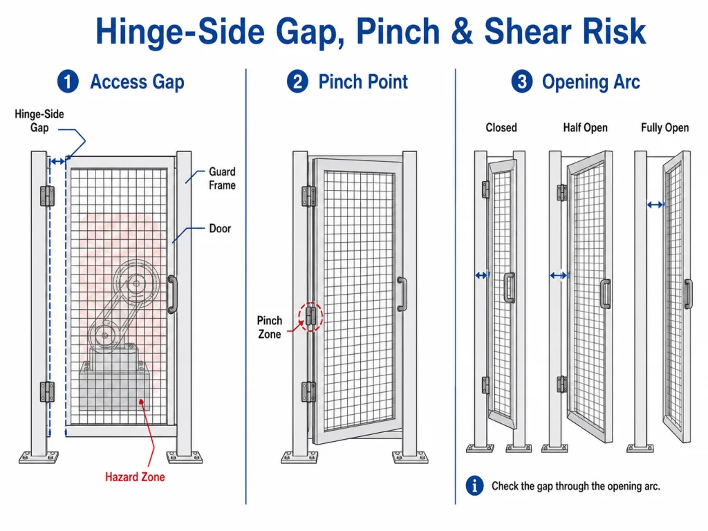
Écart en matière d'accès
Un espace entre la porte de protection et son cadre peut permettre à un doigt, une main ou un bras d'atteindre la zone de danger. L'ouverture admissible ne peut pas être réduite à une valeur unique. Elle dépend de la taille de l'ouverture, de la partie du corps concernée, de la distance par rapport au danger, de la géométrie de la protection et de l'évaluation des risques de la machine.
La norme ISO 13857:2019 définit les distances de sécurité à respecter pour les structures de protection destinées à empêcher les membres supérieurs et inférieurs d'atteindre les zones dangereuses des machines. Ces valeurs doivent être appliquées à l'ouverture réelle et à l'emplacement du danger. Le fournisseur de charnières peut fournir les caractéristiques géométriques du produit, mais c'est au constructeur de la machine qu'il revient de déterminer si la configuration de protection ainsi obtenue permet une réduction suffisante des risques.
Exposition aux risques de pincement et de cisaillement
L'écart mobile entre la charnière, le bord de la porte et le cadre peut coincer ou sectionner un doigt ou une main gantée. Vérifiez l'arc d'ouverture complet, et pas seulement la position de fermeture totale. Les charnières décalées, la flexion du cadre, la déformation du vantail et l'affaissement de la porte peuvent réduire l'écart à un angle intermédiaire.
| Dispositif de charnière | Exposition de l'articulation externe | Critique de Guard-Door |
|---|---|---|
| Charnière à tige apparente | Élevé | Vérifiez si les mains entrent naturellement en contact avec la ligne de charnière, si une protection est nécessaire et comment l'écart évolue pendant la fermeture. |
| Charnière à articulation protégée | En promotion | Cela peut limiter l'accès direct à la goupille et à l'articulation, mais l'écart entre la porte et le cadre lors du mouvement doit encore être examiné |
| Charnière encastrée | Faible exposition externe lorsqu'il est fermé | Cela réduit l'exposition visible des articulations, mais il convient tout de même d'évaluer le mouvement interne et l'espace de cisaillement entre la porte et le cadre |
Choisissez le sens d'ouverture en fonction de la disposition de la machine
Il n'existe pas de sens d'ouverture universellement valable pour tous les dispositifs de protection des machines. Pour prendre cette décision, il convient de tenir compte des éléments suivants :
- Localisation de la zone à risque
- Position de l'opérateur et position de travail normale
- Voie d'évacuation et accès d'urgence
- Circulation dans les allées, chariots élévateurs, chariots et machines situées à proximité
- Espace nécessaire pour l'entretien et le démontage des composants
- Emplacement de l'actionneur et du loquet du système de verrouillage
- La porte ouverte fait-elle obstacle à un autre dispositif de protection ou à un poste de commande ?
- La fermeture automatique reste-t-elle fiable dans l'orientation choisie ?
Un sens d'ouverture qui facilite l'accès pour l'entretien sur une machine peut obstruer une allée ou présenter un risque de choc sur une autre. Définissez le sens d'ouverture sur le plan d'assemblage avant de déterminer le sens d'ouverture, l'orientation des goupilles, le sens du ressort et la disposition des trous de fixation.
Convertir la fréquence d'accès en exigence de cycle de service
Les portes de protection des équipements de production peuvent accumuler des cycles beaucoup plus rapidement que les portes de capotage ordinaires. Le déblocage en cas de bourrage, le réglage de l'outillage, l'inspection, le chargement des matériaux, le nettoyage et les changements de série peuvent nécessiter des accès répétés au cours de chaque poste.
Estimez le rapport cyclique à partir du processus :
Nombre estimé de cycles annuels =
nombre d'ouvertures par équipe × nombre d'équipes par jour × nombre de jours d'exploitation par an
Ajoutez la durée de vie prévue et précisez ce qui doit rester acceptable après les cycles de fonctionnement. Une spécification utile ne se limite pas à “ la charnière bouge toujours ”. Elle peut inclure :
- Chute verticale maximale autorisée de la porte
- Jeu maximal de la charnière
- Fermeture automatique continue à partir de l'angle requis
- Alignement reproductible des verrous et des dispositifs de verrouillage
- Pas de feuilles fissurées, de broches desserrées ni de déformation permanente du cadre
- Aucune augmentation inacceptable de la force d'ouverture
- Aucun desserrage des fixations ni aucune fissure au niveau des soudures
Si aucun test fourni par le fournisseur ne correspond exactement à l'application, considérer les caractéristiques de cycle indiquées dans le catalogue comme préliminaires et valider la grille de production ou un dispositif de fixation représentatif.
Usure des charnières, affaissement de la porte et alignement du système de verrouillage
La charnière n'assure pas la fonction de verrouillage, mais son usure peut affecter l'alignement mécanique de l'actionneur de verrouillage. Lorsque la goupille, la douille, les vantaux, les fixations, les soudures ou le cadre se déplacent, la porte peut s'affaisser ou s'écarter de sa position fermée d'origine.
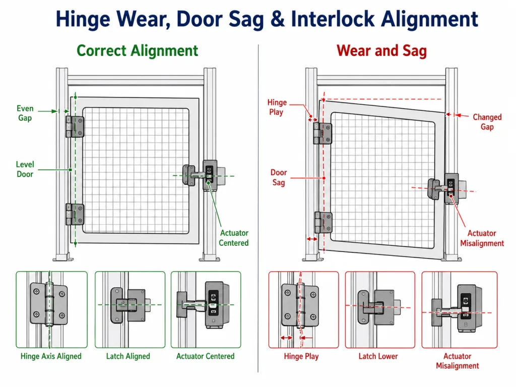
Parmi les conséquences possibles, on peut citer :
- L'actionneur pénètre dans le dispositif de verrouillage en formant un angle
- Il faut soulever ou pousser le loquet pour qu'il s'enclenche.
- Le support de l'interrupteur subit des chocs répétés
- Les arrêts intempestifs se multiplient car la position de fermeture n'est pas reproductible
- Les jeux du côté de la charnière et du côté du loquet évoluent avec le temps
- Les opérateurs ou le personnel de maintenance réajustent sans cesse le commutateur au lieu de remédier à l'usure mécanique
| Élément mécanique | Éléments à définir ou à vérifier |
|---|---|
| Jeu de charnière | Mouvement radial, axial ou angulaire admissible lors de l'homologation initiale et après les essais de cycles |
| Chute verticale de la porte | Course maximale permettant encore un enclenchement correct et l'entrée de l'actionneur |
| Répétabilité en position fermée | La porte revient à la même position de référence sans qu'il soit nécessaire de la soulever manuellement ou d'exercer une pression latérale |
| Approche par actionneur | La course d'entrée reste dans les limites mécaniques fixées par le fabricant du dispositif de verrouillage |
| Supports pour interrupteurs et loquets | Suffisamment rigide pour ne pas bouger sous l'effet d'un choc normal lors de la fermeture |
| Déformation du châssis | Le poids de la porte et la force du ressort ne provoquent pas de torsion du cadre de protection |
| Support de loquet | Le loquet répartit la charge exercée sur la porte fermée lorsque la conception l'exige |
Résistance à la manipulation et contournement prévisible des mesures de sécurité
La pression liée à la production peut inciter à contourner un dispositif de protection qui interrompt des tâches fréquentes. La conception mécanique de la charnière ne doit pas faciliter inutilement le retrait ou le contournement fortuit de ce dispositif.
En fonction du risque identifié et du plan de maintenance, le système de charnières peut comporter :
- Une goupille de charnière non amovible ou fixe
- Éléments de fixation accessibles uniquement depuis l'intérieur de la zone protégée
- Quincaillerie captive ou inviolable
- Un système de fixation dissimulé
- Une étape de mise en service contrôlée
- Un loquet ou un dispositif de retenue qui empêche le retrait lorsque le capot est fermé
Ces mesures concernent la facilité mécanique avec laquelle la porte peut être retirée. La stratégie visant à réduire les risques raisonnablement prévisibles de contournement du dispositif de verrouillage doit être traitée séparément dans le cadre de la conception de la sécurité de la machine. Ne qualifiez pas la charnière d“” anti-contournement » tant que le mécanisme exact et les limites du système ne sont pas clairement définis.
Fixation du cadre de protection et alignement après soudage
Les charnières des protecteurs de machines doivent transférer la charge de la porte vers un élément structurel du châssis ou une zone de fixation renforcée, et non vers un treillis métallique non soutenu ou un bord de panneau peu résistant. L'examen de la fixation doit notamment vérifier si l'ensemble du protecteur conserve son jeu côté charnière, sa position fermée et l'alignement de son dispositif de verrouillage après sa fabrication et une utilisation répétée.
| Construction de barrières | Parcours de montage type | Contrôle spécifique aux gardes |
|---|---|---|
| Châssis en tubes soudés | Charnière à souder ou plaque à boulonner | Vérifiez que les axes des charnières restent alignés et que l'écartement de la porte fermée reste stable après la soudure finale, le refroidissement et le retrait du gabarit. |
| Grille de protection en treillis métallique | Fixer à l'élément de châssis environnant ou à la plaque renforcée | Ne faites pas peser le poids de la porte sur le treillis non renforcé ; assurez-vous que le cadre ne se déforme pas sous le poids de la porte ou sous l'effet de la force de fermeture. |
| Panneau en tôle perforée | Charnière à visser avec support de renfort si nécessaire | Veillez à ce que le schéma de fixation ne passe pas par des perforations ouvertes et maîtrisez les déformations locales susceptibles de modifier l'écartement de la protection. |
| Cadre en profilés d'aluminium extrudés | Système de fixation compatible avec les profilés, à écrou en T ou à boulon traversant | Vérifier la déformation du profilé, le verrouillage des fixations, ainsi que la répétabilité de la position du loquet et de l'actionneur |
| Porte en tôle profilée | Fixer au niveau d'un ourlet, d'un rebord ou d'une zone renforcée | Empêcher la rotation de l'écrou à riveter, la déformation des bords et l'affaissement progressif du côté de l'emboîtement |
Pour les cadres de protection soudés, vérifiez l'alignement une fois que l'ensemble de la structure a refroidi et que le gabarit a été retiré — et non pas uniquement pendant le soudage par points. Les différentes charnières doivent partager un même axe fonctionnel dans l'ensemble fini. La porte doit s'ouvrir librement, revenir à sa position de fermeture prévue et s'enclencher dans le loquet et le dispositif de verrouillage sans qu'il soit nécessaire de la soulever ou d'exercer une pression latérale.
Pour les protections à visser, définir les modalités d'engagement des fixations, le support d'appui, les méthodes de serrage et de verrouillage, ainsi qu'un point de contrôle permettant de détecter tout desserrage. Dans le cadre d'une application à cycle intensif, le contrôle d'entretien doit se concentrer sur les soudures fissurées, les fixations desserrées, l'augmentation du jeu des charnières, la modification des écarts côté charnières et le désalignement des actionneurs, plutôt que de traiter le joint comme un simple problème de fixation d'armoire.
Scénario d'ingénierie des composites : porte d'accès à une cellule robotisée
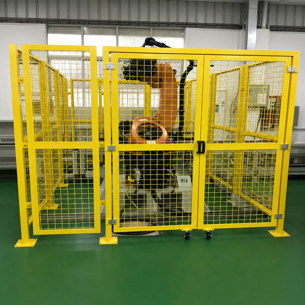
Exemple dans le domaine de l'ingénierie : Le scénario suivant illustre le processus de sélection et ne constitue ni une étude de cas client ni le résultat d'un test de produit.
Prenons l'exemple d'un portillon d'accès en treillis métallique installé sur une cellule de soudage robotisée. Les techniciens ouvrent ce portillon plusieurs fois par équipe pour accéder aux gabarits, tandis que les interventions de maintenance plus approfondies sont moins fréquentes. Le robot présente une zone de travail dangereuse située derrière le portillon ; c'est pourquoi le constructeur de la machine prévoit, dans le cadre de la conception de sécurité de celle-ci, un dispositif de protection à verrouillage mutuel au niveau de l'accès.
L'évaluation des risques précise également que le portillon doit revenir en position fermée après chaque passage. Le mécanisme de retour retenu est dimensionné et validé indépendamment du dispositif de verrouillage ; cette page évalue uniquement son incidence sur le mouvement du portillon, l'impact à la fermeture et l'alignement mécanique.
La révision mécanique se déroule comme suit :
- La masse et la largeur totales de la porte sont confirmées. Le treillis, la poignée, la plaque signalétique, les pièces de fermeture et le dispositif d'actionnement du verrouillage sont fournis.
- La fréquence d'ouverture est estimée. Le nombre d'ouvertures par service est converti en un objectif annuel et en une durée de vie prévue.
- La charnière se fixe au châssis en tubes soudés. Il n'est pas fixé au maillage non soutenu.
- La force de fermeture est testée. Le portail doit revenir de l'angle défini sans claquer ni heurter l'actionneur.
- L'ouverture du côté de la charnière est examinée. La distance de passage et le risque de pincement ou de cisaillement sont vérifiés sur toute l'amplitude d'ouverture.
- La goupille et les éléments de fixation empêchent tout retrait accidentel. La stratégie anti-contournement du dispositif de verrouillage relève toujours de la responsabilité d'un système de sécurité distinct.
- L'affaissement de la porte est mesuré après une série de cycles. L'enclenchement du loquet et la pénétration de l'actionneur restent reproductibles sans qu'il soit nécessaire de soulever le portillon à la main.
- L'accès à des fins de maintenance est défini séparément. L'entrée prolongée fait appel à la procédure d'intervention sécurisée et de maîtrise des énergies dangereuses du site, plutôt qu'à un dispositif improvisé pour maintenir la porte ouverte.
Ce scénario montre pourquoi la mention “ charnière pour porte de cellule robotisée ” ne constitue pas une spécification complète. L'exigence réelle combine en effet le mouvement, le cycle de service, la structure du châssis, le contrôle de l'écart, la retenue et l'alignement à long terme.
Quand la bonne solution, c'est la serrure — et non la charnière
Certains problèmes liés à la porte de protection ne peuvent pas être résolus en changeant la charnière.
| Problème constaté | Problème probablement lié au niveau de la garde | Pourquoi un nouveau système de charnière ne résoudrait peut-être pas le problème |
|---|---|---|
| L'ouverture du côté de la charnière est trop grande | Les dimensions de la porte ou de l'ouverture du cadre sont incorrectes | La charnière ne peut pas compenser un écart fondamentalement trop important. |
| Les opérateurs maintiennent régulièrement le portail ouvert | Un point d'accès ou un flux de travail entraîne des interruptions excessives | Une force de ressort plus importante pourrait rendre l'accès plus difficile et favoriser une nouvelle défaite. |
| Le système Interlock nécessite un réglage constant | Cadre fragile, fixation du loquet insuffisante ou support de l'actionneur mal installé | Une charnière plus solide ne suffira peut-être pas à elle seule à stabiliser l'ensemble de la structure |
| Une porte entre en collision avec des passagers circulant dans l'allée | Le sens d'ouverture ou la disposition de la machine n'est pas adapté(e) | La modification de la capacité de la charnière n'entraîne pas de modification de la course bloquée. |
| La porte est difficile à ouvrir après l'activation du mécanisme de fermeture automatique | La stratégie de fermeture automatique ou la méthode d'accès doit être réexaminée | L'augmentation du couple nuit encore davantage à la facilité d'utilisation |
| Un portail soudé se bloque après sa fabrication | Déformation due au soudage et désalignement des axes | Le remplacement de la charnière sans corriger l'alignement entraîne une nouvelle défaillance. |
Avant de demander un remplacement, distinguez bien un défaut de charnière d'un problème lié à la conception du dispositif de protection. Cela permet d'éviter des changements répétés de fournisseur qui ne s'attaquent jamais à la cause réelle du problème.
Vérification du prototype et du système de protection installé
Valider la charnière sur le dispositif de protection complet destiné à la production ou sur un gabarit représentatif validé. Un échantillon de charnière isolé ne permet pas de reproduire la flexion du cadre, la réaction du loquet, la force du ressort, l'impact de l'actionneur, la déformation due au montage ni l'effet de levier exercé par un utilisateur réel.
CHARNIÈRE DE PROTECTION DE MACHINE — PROTOTYPE ET CONTRÔLE APRÈS INSTALLATION
----------------------------------------------------
PERIMETRE DE SECURITE
[ ] La charnière n’est pas considérée comme un dispositif de verrouillage ou de contrôle de sécurité
[ ] Les exigences en matière d’évaluation des risques sont documentées par le constructeur de la machine
[ ] Tout comportement de retour requis a un objectif et un angle de départ définis

MOUVEMENT
[ ] La porte s’ouvre sur toute la plage de fonctionnement requise sans collision
[ ] Le sens d’ouverture n’obstrue pas les allées, les issues de secours, les commandes ou les équipements adjacents
[ ] La porte à fermeture automatique revient en position fermée à partir de tous les angles de départ requis
[ ] La fermeture ne provoque pas de claquement, de rebond ou d’impact inacceptable
[ ] Le maintien en position ouverte, s’il est requis, fait partie d’une condition d’intervention sécurisée définie

ÉCARTS ET RISQUES DE CONTACT
[ ] L’écart d’accès côté charnière est vérifié par rapport à l’emplacement du risque
[ ] L’écart est examiné sur l’ensemble de l’arc d’ouverture
[ ] L’exposition au pincement et au cisaillement au niveau de l’articulation et du bord de la porte est évaluée
[ ] Les protections ou la géométrie dissimulée n’introduisent pas de nouveau risque de contact caché

STRUCTURE ET FIXATION
[ ] La charge exercée sur la charnière est transférée vers un cadre structurel ou une zone de fixation renforcée
[ ] Les charnières soudées restent coaxiales après le soudage final et le refroidissement
[ ] Les éléments de fixation présentent un engagement, un appui et un verrouillage adéquats
[ ] La porte et le cadre restent rigides sous le poids de la porte et la force de fermeture spécifiée

CYCLE DE FONCTIONNEMENT ET ALIGNEMENT
[ ] Le nombre d’ouvertures par équipe et la durée de vie prévue sont définis
[ ] L’essai cyclique inclut un jeu acceptable des charnières et une chute verticale de la porte
[ ] L’alignement du loquet reste reproductible après les cycles
[ ] L’actionneur de verrouillage s’enclenche sans choc, sans soulèvement ni force latérale
[ ] Les supports de l’interrupteur et du loquet restent solidement fixés

FIXATION ET ENTRETIEN
[ ] L'axe de charnière et les fixations ne peuvent pas être retirés facilement depuis l'extérieur de la zone protégée
[ ] La méthode de démontage autorisée est documentée lorsque le portillon est démontable à des fins d'entretien
[ ] Les points d'inspection comprennent le jeu, les fixations desserrées, les fissures de soudure, l'affaissement et les changements d'alignement
Une fois ces exigences spécifiques aux agents de sécurité définies, consultez notre guide sur Comment s'approvisionner en charnières industrielles pour préparer l'appel d'offres, le dossier technique, l'examen des échantillons et le processus de validation de la production.
Questions fréquemment posées
Une charnière suffit-elle à garantir la sécurité d'une porte de protection de machine ?
Non. La charnière soutient le dispositif de protection et contrôle son mouvement mécanique. Le dispositif de verrouillage et le système de commande lié à la sécurité remplissent des fonctions distinctes. Le choix de la charnière doit s'adapter à la conception globale du dispositif de protection, mais ne saurait se substituer à l'évaluation des risques de la machine ni à la conception du système de commande de sécurité.
Chaque porte de protection d'une machine doit-elle être équipée d'une charnière à fermeture automatique ?
Non. La nécessité d'un mécanisme de fermeture automatique doit découler de l'évaluation des risques liés à la machine, de la séquence de fonctionnement, de la fréquence d'accès et du comportement prévisible de l'utilisateur. Une charnière à fermeture automatique aide la porte à revenir en position fermée, mais elle ne garantit pas la fermeture ni ne remplace un dispositif de verrouillage.
Quel jeu est acceptable du côté de la charnière d'une porte de protection ?
Il n'existe pas d'écart universel valable pour toutes les machines. L'ouverture admissible dépend de la taille de la machine, de la partie du corps susceptible de s'y glisser, de la distance par rapport au danger, de la géométrie du dispositif de protection et de l'évaluation des risques documentée. La norme ISO 13857 fournit des valeurs de distance de sécurité pour les structures de protection.
L'usure des charnières peut-elle affecter le dispositif de verrouillage d'une porte de protection ?
Oui. L'usure des charnières ou le déplacement du cadre peuvent entraîner un affaissement de la porte et éloigner l'actionneur du verrouillage de sa trajectoire d'entrée prévue. La charnière n'assure pas la fonction de verrouillage, mais il convient de vérifier l'alignement mécanique lors des essais sur prototype et lors de la maintenance.
Pourquoi la durée de vie est-elle importante pour la porte de protection d'une machine ?
Les portes de protection des machines peuvent être ouvertes à plusieurs reprises à des fins d'inspection, de chargement, de changement de série et de déblocage en cas de bourrage. Un nombre élevé de cycles peut entraîner un jeu accru au niveau des charnières, un affaissement de la porte, un desserrage des fixations et un désalignement des dispositifs de verrouillage. Définissez à la fois le nombre de cycles prévu et l'état acceptable après ces cycles.
Une porte de protection de machine doit-elle être équipée d'une charnière à maintien en position ouverte ?
Uniquement lorsque la condition de maintien en position ouverte s'inscrit dans le cadre d'une procédure définie d'accès sécurisé ou de maintenance. Une fonction de maintien en position ouverte ne doit pas être considérée comme une isolation des énergies dangereuses et ne doit pas permettre un fonctionnement normal lorsque la fonction de protection requise est désactivée.
Résumé : Définir la charnière comme faisant partie intégrante de la structure de protection
Une charnière de protection de machine fiable doit supporter l'ensemble du battant, se déplacer sur toute la course requise, maintenir des écarts contrôlés, éviter de créer un nouveau risque de pincement ou de choc, résister au cycle de service réel, empêcher tout démontage accidentel lorsque cela est nécessaire, et préserver l'alignement du loquet et du dispositif de verrouillage à mesure que l'ensemble s'use.
La charnière ne constitue qu'un élément mécanique parmi d'autres du système de protection. Le constructeur de la machine est responsable de l'évaluation des risques, de la fonction de verrouillage, du système de commande lié à la sécurité, de la prévention des démarrages intempestifs et de la validation finale de la machine dans son ensemble.
| Besoin d'aide pour évaluer une charnière de protection pour machine ? Veuillez nous communiquer le poids et la largeur du portail, la structure du cadre, le sens d'ouverture, le nombre de cycles prévu, les exigences en matière de fermeture automatique, l'écart côté charnière et le schéma de montage du dispositif de verrouillage. Notre équipe d'ingénieurs se chargera d'examiner les exigences relatives à la charnière mécanique, au montage, au mouvement et à la durabilité. Contactez nos ingénieurs → |