-
+86 13720060320
-
lanna@haitangs.com

Zawiasy do osłon maszyn i drzwi bezpieczeństwa
Zawias w osłonie maszyny lub drzwiach bezpieczeństwa pełni nie tylko funkcję podparcia panelu. Kontroluje on sposób, w jaki osłona się odchyla, czy powraca do powtarzalnej pozycji zamkniętej, jak zmienia się szczelina po stronie zawiasu w trakcie łuku otwierania oraz czy ugięcie drzwi może ostatecznie zakłócić działanie zatrzasku lub siłownika blokady.
Zawias nie jest urządzeniem zabezpieczającym maszyny. Nie jest w stanie wykryć otwartej osłony, zatrzymać niebezpiecznego ruchu, potwierdzić, że drzwi są zamknięte, ani zapobiec nieoczekiwanemu uruchomieniu. Funkcje te należą do urządzenia blokującego i systemu sterowania związanego z bezpieczeństwem. Jednak źle dobrany lub nieprawidłowo zamontowany zawias może negatywnie wpłynąć na właściwości mechaniczne, od których zależy działanie całego systemu osłon.
W niniejszym przewodniku wyjaśniono wymagania dotyczące zawiasów stosowanych w osłonach maszyn, bramkach komórek robotycznych, drzwiach dostępowych przenośników, obudowach obrabiarek oraz podobnych ruchomych osłonach. Skupia się on na właściwościach samozamykających, sile zamykania, szczelinach w linii zawiasów, narażeniu na przytrzaśnięcie i ścinanie, trwałości cyklicznej, odporności na manipulacje, montażu na ramie, wyrównaniu blokad oraz weryfikacji po montażu. W celu ogólnego doboru rodziny produktów skorzystaj z naszego przewodnika na stronie jak wybrać zawias przemysłowy.
Granica decyzyjna: Ocena ryzyka przeprowadzona przez konstruktora maszyny określa, czy osłona musi być wyposażona w blokadę sprzężoną, blokadę osłony, mechanizm samozamykający lub sterowana w inny sposób. Dostawca zawiasów może udzielić porad dotyczących wsparcia mechanicznego, ruchu, mocowania oraz trwałości, ale nie należy go traktować jako projektanta funkcji kontroli bezpieczeństwa maszyny.
Zawias jest elementem mechanicznym — nie jest to urządzenie zabezpieczające
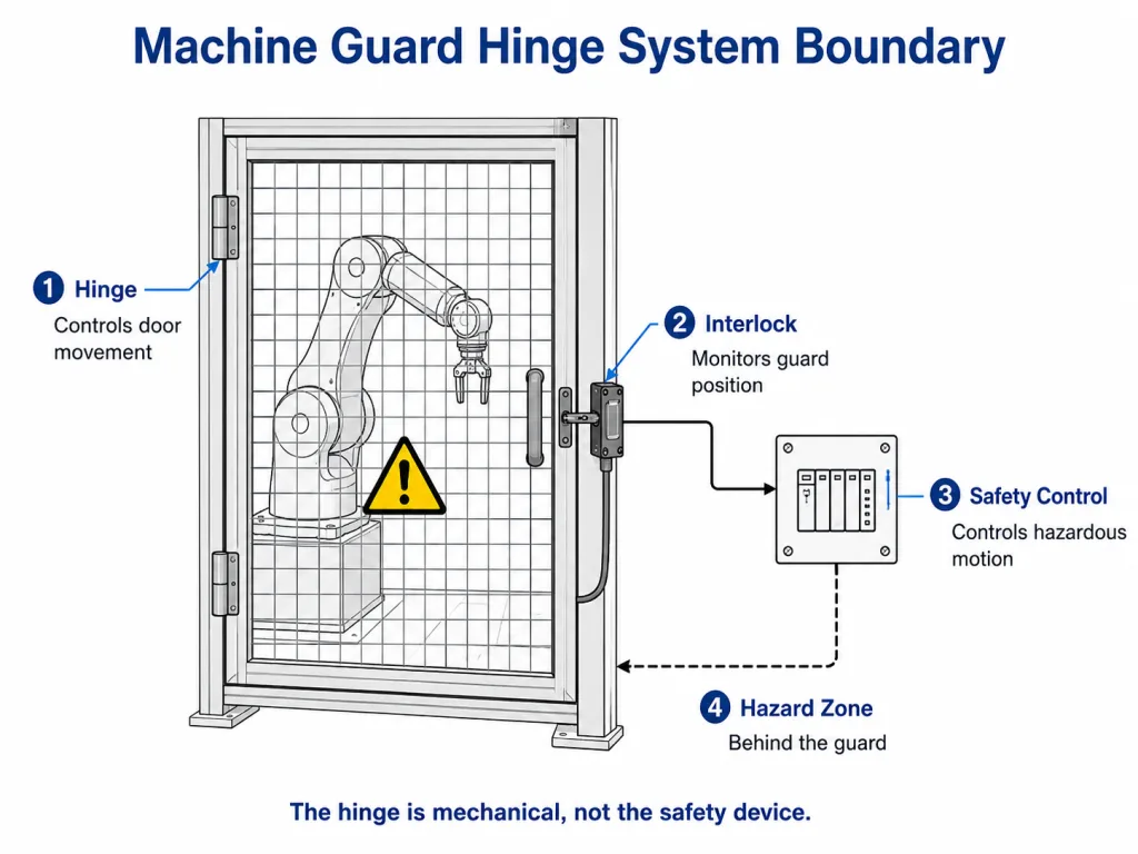
Zawias drzwi osłonowych podtrzymuje drzwi i steruje ich ruchem. W zależności od konstrukcji może on również zapewniać samozamykalność, opór przy utrzymywaniu w pozycji otwartej, określony ogranicznik lub zabezpieczenie przed przypadkowym demontażem. Nie pełni on jednak funkcji sterującej związanej z bezpieczeństwem.
Norma ISO 14120:2015 dotyczy ogólnego projektowania, konstrukcji i doboru osłon stałych i ruchomych. W szczególności oddziela ona wymagania dotyczące konstrukcji osłon od urządzeń blokujących, które są przedmiotem normy ISO 14119:2024. Norma ISO 14119 obejmuje projektowanie i dobór urządzeń blokujących związanych z osłonami oraz zawiera środki mające na celu ograniczenie racjonalnie przewidywalnego obejścia tych urządzeń.
W odniesieniu do decyzji dotyczącej zawiasów podział ten oznacza:
- The zawias podtrzymuje drzwi, steruje ich ruchem i pomaga utrzymać prawidłowe ustawienie mechaniczne.
- The mechanizm blokujący wykrywa lub monitoruje położenie osłony zgodnie z jej konstrukcją.
- The system sterowania związany z bezpieczeństwem przetwarza sygnał i steruje funkcjami maszyny stwarzającymi zagrożenie.
- The ocena ryzyka związanego z maszynami określa, jakie środki ochronne i wymagania eksploatacyjne są konieczne.
Jeśli po wydaniu polecenia zatrzymania nadal występuje stan zagrożenia, maszyna może wymagać blokady osłony lub innego środka ochronnego. Jest to decyzja dotycząca systemu bezpieczeństwa, a nie cecha zawiasu. Zawias samozamykający lub o zwiększonej wytrzymałości nie może być nigdy przedstawiany jako zamiennik blokady lub urządzenia blokującego osłonę.
Zakres norm dotyczących przeglądu zawiasów drzwi ochronnych
| Źródło | Jaki wkład wnosi do niniejszego przeglądu | Czego dostawca zawiasów nie powinien twierdzić |
|---|---|---|
| ISO 12100:2010 | Zasady oceny ryzyka i ograniczania ryzyka w odniesieniu do maszyn | Wybór tego zawiasu zastępuje ocenę ryzyka związanego z maszyną |
| ISO 14120:2015 | Ogólne wymagania dotyczące projektowania, wykonania i doboru osłon | To, że sam zawias sprawia, że cała osłona spełnia wymagania |
| ISO 14119:2024 | Urządzenia blokujące powiązane z osłonami oraz środki mające na celu ograniczenie racjonalnie przewidywalnych przypadków obejścia zabezpieczeń | Że zawias pełni funkcję blokującą lub zabezpieczającą |
Poniższe odniesienia określają granice systemu mające znaczenie dla niniejszej strony. Wymagania dotyczące odległości bezpieczeństwa są uwzględniane w przypadku analizy otwarcia po stronie zawiasów, natomiast środki kontroli nieoczekiwanego uruchomienia i energii niebezpiecznej są uwzględniane wyłącznie w ramach granic konserwacji. Dodatkowe wymagania mogą wynikać z obowiązującej normy dotyczącej konkretnej maszyny, lokalnych przepisów, wymagań klienta oraz udokumentowanej oceny ryzyka.
Przekształcenie oceny ryzyka w wymagania dotyczące zawiasów
Zawiasu nie należy dobierać wyłącznie na podstawie masy drzwi. Należy zacząć od warunków pracy osłony i przełożyć je na wymierne wymagania mechaniczne. Zdejmowany panel osłony i stałe drzwi zapewniające dostęp do maszyny mogą wymagać różnych sposobów zamocowania zawiasów; porównaj te opcje dostosowane do konkretnych zastosowań na naszej stronie Osłony maszyn i drzwiczki dostępowe strona.
| Pytanie dotyczące drzwi ochronnych | Wynikowe wymagania dotyczące zawiasów |
|---|---|
| Czy po rutynowym wejściu drzwi muszą powrócić do pozycji zamkniętej? | Wymagane zachowanie powrotne, pozycja końcowa i kontrolowane zamykanie |
| Jak często otwierane są drzwi? | Docelowa trwałość eksploatacyjna, dopuszczalne zużycie, wymagania dotyczące smarowania lub tulei |
| Czy pracownicy mogą dostać się do miejsca zagrożenia przez otwór po stronie zawiasów? | Kontrola szczeliny, przesunięcie zawiasów, zachodzenie osłony oraz weryfikacja odległości bezpieczeństwa |
| Czy dłoń może zetknąć się z poruszającą się linią zawiasu? | Ekranowanie, ukryta geometria, zmniejszona narażenie na ścinanie oraz kontrolowana siła zamykania |
| Czy strażnik musi stawiać opór, gdy próbuje się go przypadkowo usunąć lub ominąć? | Sworzeń nieusuwalny, elementy mocujące wewnętrzne, elementy mocujące zatrzymane lub mechanizm kontrolowanego zwalniania |
| Czy siłownik blokady montuje się na drzwiach? | Niewielkie ugięcie, powtarzalna pozycja zamknięta, ograniczony luz zawiasów oraz sztywne mocowanie |
| Czy osłona jest przyspawana do rurowej ramy? | Zawias przystosowany do spawania, kontrolowana sekwencja spawania oraz wyrównanie po spawaniu |
| Czy waga lub szerokość drzwi mogą wpływać na ustawienie osłony? | Należy sprawdzić, czy zawias i rama zachowują wymaganą szczelinę, położenie zatrzasku oraz wyrównanie blokady |
Tłumaczenie to pozwala uniknąć częstego błędu popełnianego podczas zamawiania: zamawiania zawiasów opisanych jako “o zwiększonej wytrzymałości” lub “spełniających normy bezpieczeństwa” bez określenia, jakie funkcje produkt ten faktycznie musi spełniać. Opisy te mają niewielką wartość, o ile nie są poparte mierzalnymi danymi dotyczącymi geometrii, obciążenia, ruchu, cyklu pracy oraz warunków montażu.
Jakie zmiany w mechanizmie samozamykającym wprowadzono w drzwiach osłony maszyny
Nie każde drzwiczki osłony maszyny muszą zamykać się automatycznie. Wymóg ten powinien wynikać z oceny ryzyka związanego z maszyną, sekwencji pracy, częstotliwości dostępu oraz przewidywalnych zachowań użytkowników. W przypadkach, w których wymagane jest samozamknięcie, jego celem jest ułatwienie powrotu ruchomej osłony do określonej pozycji zamkniętej po rutynowym dostępie.
Samozamykacz nie gwarantuje, że drzwi są całkowicie zamknięte, nie wykrywa położenia osłony i nie zatrzymuje niebezpiecznego ruchu. Funkcje te pozostają w gestii urządzenia blokującego oraz systemu sterowania związanego z bezpieczeństwem. Podczas przeglądu zawiasów należy sprawdzić kąt powrotu, końcowe położenie zatrzasku, dopuszczalny wysiłek potrzebny do otwarcia, prędkość zamykania, odbicie oraz współdziałanie z siłownikiem blokady.
Mechanizm sprężynowy, dobór momentu obrotowego, sposób regulacji oraz wybór między zawiasem sprężynowym a samozamykaczem powinny zostać omówione w osobnym samozamykająca się prowadnica zawiasu sprężynowego. Na tej stronie przedstawiono wyłącznie konsekwencje związane z osłoną: kontrolowane zamykanie, narażenie na przygniecenie i uderzenie, reakcja ramy, załączenie zatrzasku oraz powtarzalne ustawienie siłownika.
Granice obszaru konserwacji: Jeśli osłona samozamykająca się musi pozostać otwarta podczas konserwacji, sposób jej utrzymania w pozycji otwartej należy skoordynować z procedurą bezpiecznej interwencji oraz procedurą kontroli energii niebezpiecznej dla danej maszyny. Otwarta osłona lub zawias utrzymujący ją w pozycji otwartej nie stanowią metody izolacji energii. Norma ISO 14118:2017 dotyczy wbudowanych środków zapobiegających nieoczekiwanemu uruchomieniu, natomiast serwisowanie i konserwacja w Stanach Zjednoczonych mogą również podlegać przepisom OSHA 29 CFR 1910.147.
Siła zamykająca nie może stwarzać nowego zagrożenia
Samozamykające się drzwiczki osłonowe powinny niezawodnie wracać do pozycji wyjściowej bez gwałtownego trzaskania. Większy moment sprężyny niekoniecznie oznacza większe bezpieczeństwo.
Zbyt duży moment dokręcania może:
- Zwiększyć siłę potrzebną do otwarcia ponad poziom, który operatorzy są w stanie wywierać bez trudności
- Zwiększenie narażenia na przygniecenie lub uderzenie na krawędzi zamykającej
- Uderzaj kilkakrotnie w zatrzask lub siłownik blokady
- Przyspiesza zużycie zawiasów, elementów mocujących i ramy
- Spowodować, że lekka rama osłonowa ulegnie skręceniu zamiast zamknąć się prostopadle
- Zachęcaj użytkowników do podparcia lub pokonania bariery, ponieważ normalny dostęp staje się uciążliwy
Należy ocenić sposób zamykania się bramy w pełnej wersji produkcyjnej. Pusta rama lub nieobciążony prototyp mogą zamykać się zupełnie inaczej po zamontowaniu siatki, uchwytów, tabliczek, okien, zatrzasków, okablowania i elementów blokujących.
Sprawdzenie prototypu: Należy sprawdzić, czy brama zamyka się z wymaganych kątów początkowych, nie odbija się od zatrzasku, nie uderza w siłownik blokady oraz nie powoduje niedopuszczalnego uderzenia ani nie stwarza zagrożenia przygnieceniem na końcowej krawędzi zamykania.
Ograniczanie ryzyka wciągnięcia, przygniecenia i przycięcia w obszarze linii zawiasów
Strona zawiasowa ruchomej osłony może stwarzać kilka różnych zagrożeń. Należy je omówić osobno.
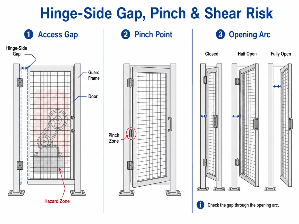
Luka w dostępie
Szczelina między drzwiczkami osłony a ościeżnicą może umożliwić włożenie palca, dłoni lub ramienia do strefy zagrożenia. Dopuszczalnej szerokości szczeliny nie da się sprowadzić do jednej uniwersalnej wartości. Zależy ona od wielkości otworu, rozpatrywanej części ciała, odległości od źródła zagrożenia, geometrii osłony oraz oceny ryzyka związanego z maszyną.
Norma ISO 13857:2019 określa wartości odległości bezpieczeństwa dla konstrukcji ochronnych mających na celu zapobieganie przedostawaniu się kończyn górnych i dolnych do stref zagrożenia maszyn. Wartości te należy zastosować do rzeczywistego otworu i lokalizacji zagrożenia. Dostawca zawiasów może dostarczyć dane geometryczne produktu, jednak to konstruktor maszyny musi ustalić, czy wynikający z tego układ osłon zapewnia wystarczające ograniczenie ryzyka.
Narażenie na ściskanie i ścinanie
Ruchoma szczelina między przegubem zawiasu, krawędzią drzwi a ościeżnicą może spowodować uwięzienie lub przycięcie palca lub dłoni w rękawiczce. Należy sprawdzić cały łuk otwarcia — nie tylko pozycję całkowicie zamkniętą. Przesunięte zawiasy, ugięcie ościeżnicy, odkształcenie skrzydła oraz ugięcie drzwi mogą powodować zmniejszenie szczeliny przy pośrednim kącie otwarcia.
| Układ zawiasów | Odsłonięcie zewnętrznego przegubu | Recenzja Guard-Door |
|---|---|---|
| Zawias z odsłoniętą tuleją | Wysoki | Sprawdź, czy dłonie w naturalny sposób stykają się z linią zawiasów, czy konieczne jest zastosowanie osłony oraz jak zmienia się szczelina podczas zamykania |
| Zawias z osłoniętym przegubem | Obniżona | Może ograniczyć bezpośredni dostęp do sworznia i przegubu, jednak nadal należy sprawdzić szczelinę między ruchomymi drzwiami a ościeżnicą |
| Ukryty zawias | Niska ekspozycja na czynniki zewnętrzne w stanie zamkniętym | Ogranicza widoczną ekspozycję przegubów, jednak nadal należy ocenić ruchy wewnętrzne oraz szczelinę ścinającą między drzwiami a ościeżnicą |
Wybierz kierunek otwierania na podstawie schematu maszyny
Nie ma jednego, uniwersalnego kierunku otwierania, który byłby właściwy dla każdej osłony maszyny. Przy podejmowaniu decyzji należy wziąć pod uwagę:
- Lokalizacja strefy zagrożenia
- Podejście operatora i normalna pozycja robocza
- Droga ewakuacyjna i wejście awaryjne
- Ruch w korytarzach, wózki widłowe, wózki transportowe i sąsiednie maszyny
- Wymagana przestrzeń na konserwację i demontaż podzespołów
- Umiejscowienie siłownika blokady i zatrzasku
- Czy otwarta brama zasłania inne urządzenie zabezpieczające lub stanowisko sterownicze
- Czy mechanizm samozamykający działa niezawodnie w wybranej orientacji
Kierunek, który zapewnia dobry dostęp do konserwacji w jednym urządzeniu, może blokować przejście lub stwarzać zagrożenie uderzeniem w innym. Należy określić kierunek otwierania na rysunku montażowym przed podjęciem decyzji dotyczącej strony otwierania, orientacji sworznia, kierunku działania sprężyny oraz rozmieszczenia otworów montażowych.
Przeliczenie częstotliwości dostępu na wymagania dotyczące cyklu pracy
Drzwi ochronne w urządzeniach produkcyjnych mogą osiągać liczbę cykli znacznie szybciej niż zwykłe drzwi obudowy. Usuwanie zacięć, regulacja oprzyrządowania, kontrola, załadunek materiałów, czyszczenie i przezbrojenie mogą wymagać wielokrotnego dostępu podczas każdej zmiany.
Oszacuj cykl pracy na podstawie procesu:
Szacowana liczba cykli rocznych =
liczba otwarć na zmianę × liczba zmian dziennie × liczba dni roboczych w roku
Należy uwzględnić przewidywany okres eksploatacji oraz określić, jakie parametry muszą pozostać w dopuszczalnym zakresie po cyklu obciążeń. Przydatna specyfikacja to nie tylko stwierdzenie, że “zawias nadal się porusza”. Może ona obejmować:
- Maksymalny dopuszczalny spadek drzwi w płaszczyźnie pionowej
- Maksymalny luz zawiasu
- Ciągłe samozamknięcie od wymaganego kąta
- Powtarzalne ustawianie zatrzasku i blokady
- Brak pękniętych listew, poluzowanych kołków ani trwałego odkształcenia ramy
- Brak niedopuszczalnego wzrostu siły potrzebnej do otwarcia
- Brak poluzowania elementów mocujących ani pęknięć spoin
Jeśli żaden test dostawcy nie odpowiada dokładnie danemu zastosowaniu, należy traktować parametry cyklu podane w katalogu jako wstępne i zweryfikować bramkę przeznaczoną do produkcji lub reprezentatywny uchwyt.
Zużycie zawiasów, ugięcie drzwi i wyrównanie blokady
Zawias nie pełni funkcji blokującej, ale jego zużycie może wpływać na mechaniczne ustawienie siłownika blokady. Gdy sworzeń, tuleja, skrzydła, elementy mocujące, spoiny lub rama zaczynają się przesuwać, drzwi mogą opadać lub odchylać się od pierwotnego położenia zamkniętego.
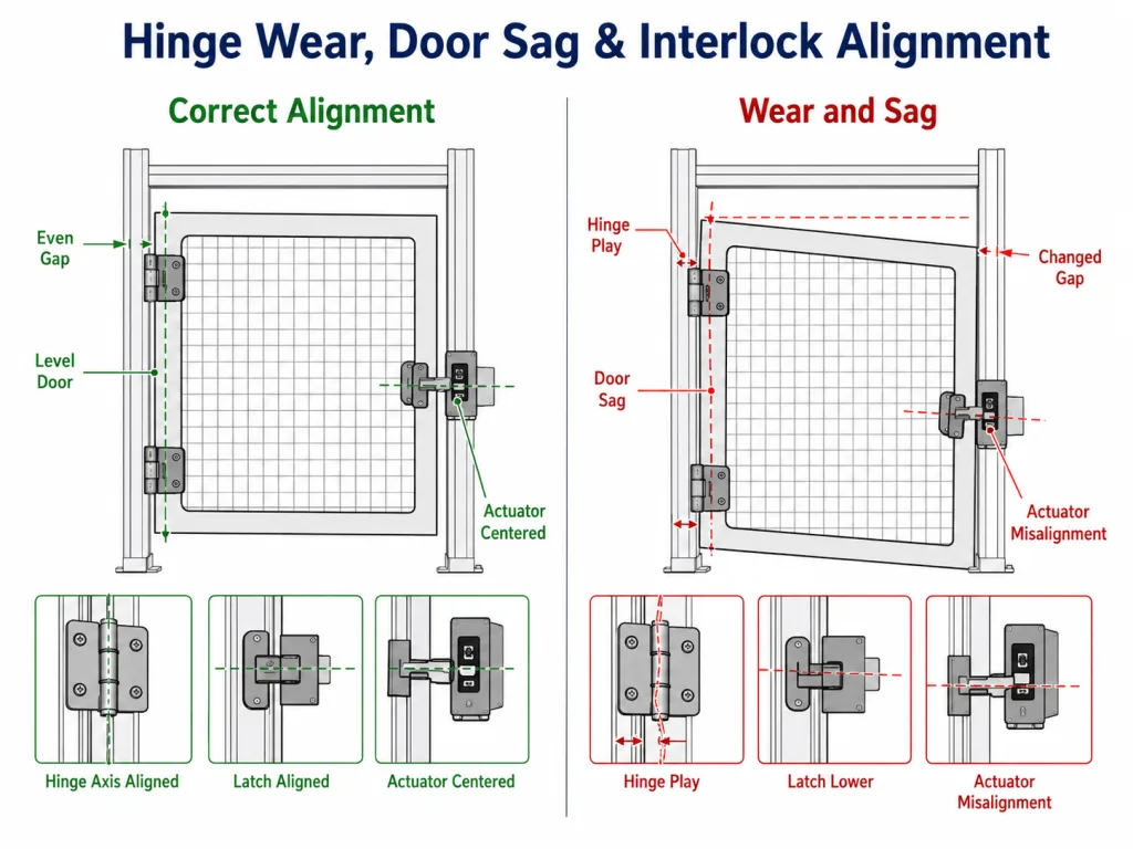
Możliwe konsekwencje to między innymi:
- Siłownik wjeżdża do blokady pod kątem
- Aby osłona się zatrzasnęła, trzeba ją podnieść lub popchnąć
- Wspornik przełącznika jest narażony na powtarzające się uderzenia
- Liczba niepożądanych zatrzymań wzrasta, ponieważ pozycja zamknięta nie jest powtarzalna
- Szczeliny po stronie zawiasów i po stronie zatrzasku zmieniają się z upływem czasu
- Operatorzy lub pracownicy utrzymania ruchu wielokrotnie regulują przełącznik zamiast usunąć skutki zużycia mechanicznego
| Element mechaniczny | Co należy zdefiniować lub zweryfikować |
|---|---|
| Luz zawiasów | Dopuszczalny ruch promieniowy, osiowy lub kątowy w momencie pierwszego zatwierdzenia oraz po cyklu prób |
| Pionowy skok drzwi | Maksymalny zakres ruchu, który nadal pozwala na prawidłowe zamknięcie zatrzasku i wprowadzenie siłownika |
| Powtarzalność w pozycji zamkniętej | Drzwi powracają do tej samej pozycji wyjściowej bez konieczności ręcznego podnoszenia lub wywierania nacisku z boku |
| Podejście oparte na siłownikach | Ścieżka wprowadzania pozostaje w granicach parametrów mechanicznych określonych przez producenta blokady |
| Wsporniki przełączników i zatrzasków | Wystarczająco sztywne, by nie ulegać przemieszczeniu pod wpływem siły występującej podczas normalnego zamykania |
| Ugięcie ramy | Ciężar drzwi i siła sprężyny nie powodują skręcania ramy osłonowej |
| Podpora zatrzasku | Mechanizm zatrzaskowy przejmuje obciążenie przy zamkniętych drzwiach tam, gdzie wymaga tego konstrukcja |
Odporność na manipulację i przewidywalne obejście zabezpieczeń
Presja związana z produkcją może skłaniać do omijania zabezpieczenia, które utrudnia wykonywanie powtarzających się zadań. Konstrukcja mechanicznego zawiasu nie powinna sprawiać, że przypadkowe zdjęcie lub ominięcie zabezpieczenia będzie niepotrzebnie łatwe.
W zależności od udokumentowanego ryzyka i planu konserwacji w konstrukcji zawiasów można zastosować:
- Sworzeń zawiasowy nieusuwalny lub zatrzymany
- Elementy mocujące dostępne wyłącznie od wewnątrz obszaru zabezpieczonego
- Okucia zamykane na klucz lub zabezpieczone przed manipulacją
- Ukryty sposób montażu
- Etap kontrolowanego wprowadzenia do użytku
- Zatrzask lub blokada uniemożliwiająca podniesienie osłony, gdy jest ona zamknięta
Środki te dotyczą łatwości mechanicznego demontażu drzwi. Strategia mająca na celu ograniczenie racjonalnie przewidywalnego obejścia urządzenia blokującego musi zostać uwzględniona oddzielnie w ramach projektowania bezpieczeństwa maszyny. Nie należy określać zawiasu jako “zabezpieczonego przed obejściem”, chyba że dokładny mechanizm i granice systemu są jasno określone.
Mocowanie ramy ochronnej i wyrównanie po spawaniu
Zawiasy osłon maszyn powinny przenosić obciążenie drzwi na element konstrukcyjny ramy lub wzmocnioną strefę mocowania — a nie na niepodpartą siatkę drucianą lub słabą krawędź panelu. Ocena montażu powinna skupiać się na tym, czy cała osłona zachowuje szczelinę po stronie zawiasów, pozycję zamkniętą oraz wyrównanie blokady po wyprodukowaniu i wielokrotnym użytkowaniu.
| Konstrukcja osłony | Typowy przebieg montażu | Kontrola dotycząca konkretnego strażnika |
|---|---|---|
| Spawana rama rurowa | Zawias do przyspawania lub płyta do przykręcania przelotowego | Należy sprawdzić, czy osie zawiasów pozostają wyrównane, a szczelina przy zamkniętych drzwiach zachowuje stałą szerokość po zakończeniu spawania, schłodzeniu i zwolnieniu z uchwytu |
| Osłona z siatki drucianej | Przymocować do otaczającego elementu ramy lub wzmocnionej płyty | Nie należy przenosić obciążenia drzwi przez siatkę bez podparcia; należy sprawdzić, czy rama nie wygina się pod ciężarem drzwi lub siłą zamykania |
| Panel z blachy perforowanej | Zawias przykręcany z podparciem w razie potrzeby | Należy unikać umieszczania elementów mocujących w obszarach otwartych perforacji oraz zapobiegać lokalnym odkształceniom, które mogłyby wpłynąć na szerokość szczeliny ochronnej |
| Rama z profili aluminiowych | Uchwyt dostosowany do profilu, nakrętka typu T lub system śrub przelotowych | Należy sprawdzić ugięcie profilu, zablokowanie elementów mocujących oraz powtarzalność położenia zatrzasku i siłownika |
| Drzwi z tłoczonej blachy | Zamontować przy obszyciu, kołnierzu zwrotnym lub w strefie wzmocnionej | Należy zapobiegać obracaniu się nakrętki nitowej, odkształcaniu krawędzi oraz stopniowemu ugięciu po stronie połączenia |
W przypadku spawanych ram ochronnych należy sprawdzić wyrównanie dopiero po całkowitym ostygnięciu konstrukcji i zdjęciu przyrządu mocującego — a nie tylko podczas spawania punktowego. W gotowym zespole wszystkie zawiasy muszą leżeć na jednej osi. Drzwi powinny otwierać się swobodnie, powracać do zamierzonej pozycji zamkniętej oraz zatrzaskiwać się i blokować bez konieczności podnoszenia lub wywierania nacisku bocznego.
W przypadku osłon montowanych na śruby należy określić sposób mocowania elementów łączących, podparcie tylne, metody dokręcania i blokowania oraz punkt kontroli pod kątem poluzowania. W zastosowaniach o dużej częstotliwości cykli konserwacja powinna skupiać się na pękniętych spawach, poluzowanych elementach mocujących, zwiększonym luzie zawiasów, zmianach szczelin po stronie zawiasów oraz niewspółosiowości siłowników, zamiast traktować połączenie jako ogólny problem z mocowaniem obudowy.
Scenariusz z zakresu inżynierii kompozytowej: Brama dostępowa do komory robota
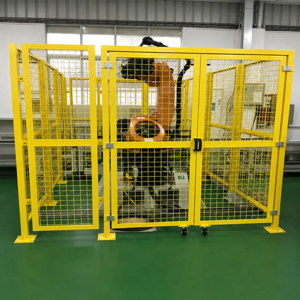
Przykład z dziedziny inżynierii: Poniższy scenariusz ilustruje proces wyboru i nie stanowi studium przypadku klienta ani wyniku testu produktu.
Weźmy pod uwagę bramkę dostępową z siatki drucianej w komórce spawalniczej z robotem. Technicy otwierają bramkę kilka razy na zmianę, aby uzyskać dostęp do uchwytu, natomiast bardziej kompleksowe prace konserwacyjne odbywają się rzadziej. Za bramką znajduje się strefa niebezpieczna robota, dlatego producent maszyny przewidział w projekcie bezpieczeństwa maszyny osłonę dostępową z blokadą.
W ramach oceny ryzyka ustalono również, że brama powinna powrócić do pozycji zamkniętej po rutynowym przejściu. Wybrany mechanizm powrotny jest dobierany i weryfikowany niezależnie od urządzenia blokującego; na tej stronie oceniono jedynie jego wpływ na ruch bramy, siłę uderzenia podczas zamykania oraz wyrównanie mechaniczne.
Kontrola mechaniczna przebiega w następujący sposób:
- Potwierdzono całkowitą masę i szerokość bramy. W zestawie znajdują się siatka, uchwyt, tabliczka, elementy zamka oraz element uruchamiający blokadę.
- Częstotliwość otwarcia jest szacowana. Liczba otwarć na zmianę jest przeliczana na roczny cel cyklu oraz przewidywany okres eksploatacji.
- Zawias mocuje się do spawanej rurowej ramy. Nie jest połączony z siatką bez podparcia.
- Sprawdzana jest siła zamykania. Brama musi powrócić z ustawionego kąta bez trzaskania i bez uderzania w siłownik.
- Przeanalizowano otwór po stronie zawiasów. W całym zakresie otwarcia sprawdzana jest odległość sięgania oraz narażenie na przygniecenie i ścinanie.
- Szpilka i elementy mocujące są odporne na przypadkowe wyjęcie. Strategia zapobiegania obejściu blokady pozostaje odrębnym zadaniem systemu bezpieczeństwa.
- Po zakończeniu cyklu mierzy się ugięcie drzwi. Zatrzaskowanie i wsunięcie siłownika zachowują powtarzalność bez konieczności ręcznego podnoszenia bramki.
- Dostęp w celu konserwacji jest określony oddzielnie. W przypadku wejścia rozszerzonego stosuje się procedurę bezpiecznej interwencji i kontroli energii niebezpiecznej obowiązującą w zakładzie, a nie prowizoryczne podparcie drzwi.
Ten scenariusz pokazuje, dlaczego sformułowanie “zawias do bramki komórki robotycznej” nie stanowi pełnej specyfikacji. Rzeczywiste wymagania obejmują ruch, cykl pracy, konstrukcję ramy, kontrolę szczeliny, utrzymywanie elementów oraz długoterminowe wyrównanie.
Kiedy właściwym rozwiązaniem jest osłona, a nie zawias
Niektórych problemów związanych z drzwiami osłonowymi nie da się rozwiązać poprzez wymianę zawiasu.
| Zauważony problem | Prawdopodobnie problem na poziomie straży | Dlaczego inny zawias może nie rozwiązać problemu |
|---|---|---|
| Otwór po stronie zawiasów jest zbyt duży | Wymiary otworu drzwiowego lub ościeżnicy są nieprawidłowe | Zawias nie jest w stanie zniwelować zasadniczo zbyt dużej szczeliny |
| Operatorzy wielokrotnie podtrzymują bramę w pozycji otwartej | Punkt dostępowy lub proces powoduje nadmierne zakłócenia | Większa siła sprężyny może utrudnić dostęp i przyczynić się do dalszych niepowodzeń |
| System blokady wymaga ciągłej regulacji | Słaba rama, słabe mocowanie zatrzasku lub nieprawidłowy wspornik siłownika | Samo wzmocnienie zawiasu może nie wystarczyć do ustabilizowania całej konstrukcji |
| Brama zderza się z ruchem w przejściu | Kierunek otwarcia lub rozmieszczenie maszyn jest nieodpowiednie | Zmiana nośności zawiasu nie wpływa na zablokowaną ścieżkę ruchu |
| Po zwiększeniu siły samozamykania drzwi trudno się otwierają | Należy dokonać przeglądu strategii samozamknięcia lub metody dostępu | Zwiększenie momentu obrotowego jeszcze bardziej pogarsza komfort użytkowania |
| Spawana brama zacina się po wykonaniu | Odkształcenia spawalnicze i niewspółosiowość | Wymiana zawiasu bez skorygowania ustawienia prowadzi do ponownego wystąpienia usterki |
Przed złożeniem wniosku o wymianę należy odróżnić usterkę zawiasu od problemu związanego z rozmieszczeniem osłon. Pozwoli to uniknąć ciągłych zmian dostawców, które nigdy nie rozwiązują prawdziwej przyczyny problemu.
Weryfikacja prototypu i systemu „Installed-Guard”
Należy zatwierdzić zawias na kompletnej osłonie przeznaczonej do produkcji seryjnej lub na reprezentatywnym, zatwierdzonym uchwycie. Luźna próbka zawiasu nie pozwala odtworzyć ugięcia ramy, reakcji zatrzasku, siły sprężyny, uderzenia siłownika, odkształcenia montażowego ani rzeczywistej siły wywieranej przez użytkownika.
ZAWIAS OSŁONY MASZYNY — PROTOTYP I KONTROLA PO MONTAŻU
----------------------------------------------------
GRANICE BEZPIECZEŃSTWA
[ ] Zawias nie jest traktowany jako blokada ani urządzenie kontroli bezpieczeństwa
[ ] Wymagania dotyczące oceny ryzyka są udokumentowane przez producenta maszyny
[ ] Każde wymagane zachowanie powrotne ma określony cel i kąt początkowy

RUCH
[ ] Drzwi otwierają się w wymaganym zakresie roboczym bez kolizji
[ ] Kierunek otwierania nie blokuje przejść, dróg ewakuacyjnych, elementów sterujących ani sąsiednich urządzeń
[ ] Drzwi samozamykające się powracają do pozycji zamkniętej ze wszystkich wymaganych kątów początkowych
[ ] Zamknięcie nie powoduje niedopuszczalnego trzasku, odbicia ani uderzenia
[ ] Funkcja utrzymania w pozycji otwartej, jeśli jest wymagana, stanowi część zdefiniowanego bezpiecznego warunku interwencji

SZCZELINY I ZAGROŻENIA ZWIĄZANE Z KONTAKTEM
[ ] Szczelina dostępowa po stronie zawiasów jest sprawdzana pod kątem lokalizacji zagrożenia
[ ] Szczelina jest sprawdzana na całym łuku otwarcia
[ ] Oceniane jest narażenie na przytrzaśnięcie i ścinanie w okolicy przegubu i krawędzi drzwi
[ ] Osłony lub ukryta geometria nie powodują powstania innego ukrytego zagrożenia związanego z kontaktem

KONSTRUKCJA I MOCOWANIE
[ ] Obciążenie zawiasów przenoszone jest na ramę konstrukcyjną lub wzmocnioną strefę mocowania
[ ] Zawiasy spawane pozostają współosiowe po zakończeniu spawania i ostygnięciu
[ ] Elementy mocujące charakteryzują się odpowiednim zazębieniem, podparciem i blokadą
[ ] Drzwi i ościeżnica zachowują sztywność pod ciężarem drzwi i przy określonej sile zamykania

CYKL PRACY I WYRÓWNANIE
[ ] Określono liczbę otwarć na zmianę oraz przewidywaną żywotność
[ ] Test cykliczny obejmuje dopuszczalny luz zawiasów i pionowe opadanie drzwi
[ ] Wyrównanie zatrzasku pozostaje powtarzalne po cyklu pracy
[ ] Siłownik blokady wsuwa się bez uderzenia, podnoszenia ani siły bocznej
[ ] Uchwyty przełącznika i zatrzasku pozostają zamocowane

ZABEZPIECZENIE I KONSERWACJA
[ ] Sworzeń zawiasu i elementy mocujące nie mogą być przypadkowo usunięte z zewnątrz obszaru chronionego
[ ] W przypadku bram, które można zdemontować w celu serwisowania, udokumentowano autoryzowaną metodę demontażu
[ ] Punkty kontroli obejmują luz, poluzowane elementy mocujące, pęknięcia spawów, ugięcie oraz zmianę wyrównania
Po określeniu tych wymagań dotyczących konkretnych stanowisk ochroniarzy skorzystaj z naszego przewodnika na temat jak pozyskać zawiasy przemysłowe w celu przygotowania zapytania ofertowego, dokumentacji projektowej, oceny próbek oraz procesu zatwierdzania produkcji.
Często zadawane pytania
Czy zawias sprawia, że drzwi osłony maszyny są bezpieczne?
Nie. Zawias podtrzymuje osłonę i steruje jej ruchem mechanicznym. Urządzenie blokujące i system sterowania związany z bezpieczeństwem pełnią odrębne funkcje. Dobór zawiasów musi być dostosowany do całościowej konstrukcji osłony, ale nie może zastąpić oceny ryzyka związanego z maszyną ani projektu systemu sterowania bezpieczeństwa.
Czy każde drzwiczki osłony maszyny muszą być wyposażone w zawias samozamykający?
Nie. Konieczność zastosowania mechanizmu samozamykającego powinna wynikać z oceny ryzyka związanego z maszyną, sekwencji pracy, częstotliwości dostępu oraz przewidywalnych zachowań użytkowników. Zawias samozamykający ułatwia powrót drzwi do pozycji zamkniętej, ale nie gwarantuje ich zamknięcia ani nie zastępuje blokady.
Jaka szerokość szczeliny jest dopuszczalna po stronie zawiasów drzwi osłonowych?
Nie ma jednej uniwersalnej szerokości szczeliny, która miałaby zastosowanie do wszystkich maszyn. Dopuszczalna szerokość szczeliny zależy od jej rozmiarów, części ciała, która mogłaby się przez nią przedostać, odległości od źródła zagrożenia, geometrii osłony oraz udokumentowanej oceny ryzyka. Norma ISO 13857 określa wartości odległości bezpieczeństwa dla konstrukcji ochronnych.
Czy zużycie zawiasów może wpłynąć na działanie blokady drzwi osłonowych?
Tak. Zużycie zawiasów lub przemieszczenie ościeżnicy może spowodować ugięcie drzwi i odsunięcie siłownika blokady od przewidzianej ścieżki ruchu. Zawias nie pełni funkcji blokującej, jednak podczas testów prototypu i konserwacji należy sprawdzić jego mechaniczne ustawienie.
Dlaczego trwałość eksploatacyjna ma znaczenie w przypadku drzwi osłonowych maszyn?
Drzwi osłon maszyn można wielokrotnie otwierać w celu przeprowadzenia kontroli, załadunku, zmiany konfiguracji oraz usunięcia zacięć. Duża liczba cykli może powodować luz w zawiasach, ugięcie drzwi, poluzowanie elementów mocujących oraz niewspółosiowość blokad. Należy określić zarówno przewidywaną liczbę cykli, jak i dopuszczalny stan po ich wykonaniu.
Czy w drzwiach osłonowych maszyny należy zastosować zawias utrzymujący je w pozycji otwartej?
Tylko wtedy, gdy stan przytrzymania otwarcia stanowi część określonej procedury bezpiecznego dostępu lub konserwacji. Funkcja przytrzymania otwarcia nie może być traktowana jako odłączenie niebezpiecznej energii i nie powinna umożliwiać normalnej pracy przy wyłączonej wymaganej funkcji ochronnej.
Podsumowanie: Określenie zawiasu jako części konstrukcji osłony
Niezawodny zawias osłony maszyny musi utrzymywać całą bramę, poruszać się w wymaganym zakresie ruchu, zapewniać kontrolowane szczeliny, nie stwarzać nowego zagrożenia przygnieceniem lub uderzeniem, wytrzymywać rzeczywisty cykl pracy, być odporny na przypadkowe wyjęcie tam, gdzie jest to wymagane, oraz zachowywać prawidłowe ustawienie zatrzasku i blokady w miarę zużywania się zespołu.
Zawias stanowi jedynie jeden z elementów mechanicznych systemu zabezpieczeń. Producent maszyny jest odpowiedzialny za ocenę ryzyka, funkcję blokady, układ sterowania związany z bezpieczeństwem, zabezpieczenie przed nieoczekiwanym uruchomieniem oraz ostateczną walidację całej maszyny.
| Potrzebujesz pomocy przy recenzowaniu zawiasu osłony maszyny? Prosimy o podanie masy bramy, jej szerokości, konstrukcji ościeżnicy, kierunku otwierania, przewidywanej liczby cykli, wymogu samozamykania, szczeliny po stronie zawiasów oraz schematu montażu blokady. Nasz zespół inżynierów może przeanalizować wymagania dotyczące mechaniki zawiasów, montażu, ruchu oraz trwałości. Skontaktuj się z naszymi inżynierami → |