-
+86 13720060320
-
lanna@haitangs.com

الارتداد في مفصل العزم، واللعب الحر، والارتداد الزنبركي
قد تستوفي مفصلة عزم الدوران مواصفات العزم الاسمي المحددة لها، ومع ذلك قد يظل الشعور بعدم الدقة سائدًا عند استخدام الشاشة أو الغطاء أو لوحة التحكم. يوقف المشغل الحركة عند الزاوية المقصودة، ثم يحرر اللوحة، فيلاحظ أنها تتحرك. وعند عكس الاتجاه، تتحرك اليد قبل أن تستجيب اللوحة. وحول الموضع الثابت، تبدو منطقة زاوية صغيرة غير محكمة. غالبًا ما يتم الإبلاغ عن هذه الملاحظات على أنها مشكلة واحدة، لكن التراخي في مفصلة عزم الدوران، واللعب الحر، والارتداد الزنبركي هي سلوكيات مختلفة وتتطلب قياسات مختلفة.
لا تتحدد دقة تحديد الموضع بعزم الدوران وحده. فهي تعتمد على المفصلة، ووصلات العمود واللوحة، ومثبتات التثبيت، والدعامات، وصلابة اللوحة، ونقطة القياس، واتجاه الاقتراب، والحمل المطبق، والوقت الذي يتم فيه أخذ القراءة. ولذلك، فإن المواصفات المفيدة هي تلك التي تصف السلوك الفعلي بعد التركيب وظروف الاختبار التي تؤدي إلى هذا السلوك.
النطاق: يشرح هذا المقال كيفية تحديد وفحص خطأ الموضع الزاوي في آلية مفصلية تعمل بعزم الدوران. ولا يحدد المقال عزم الدوران اللازم لدعم اللوحة. قم بإجراء ذلك الحساب المنفصل أولاً، ثم استخدم الطريقة الواردة هنا لتحديد الدرجة التي يجب أن تستجيب بها المجموعة وتستقر بدقة.
يجب تحديد حدود منفصلة لـ «تراخي مفصل العزم» و«اللعب الحر» و«الارتداد الزنبركي»
تتداخل هذه المصطلحات في المحادثات العادية. لكن لا ينبغي أن تتداخل في الرسم أو مخطط الاختبار أو تقرير القبول. حدد كل سلوك بناءً على توقيت حدوث الحركة والموضعين اللذين تتم مقارنتهما.
لم يتم توحيد مصطلحات الموردين بشكل كامل. تستخدم بعض أوراق البيانات مصطلحات مثل «الارتداد» أو «اللعب» أو «اللعب الحر» أو «الحركة المفقودة» بشكل متبادل. قارن بين مدخلات الاختبار، ومراجع القياس، وعتبة الاستجابة، والزاوية المُبلغ عنها — لا تقتصر على التسمية وحدها.
تظهر ردود فعل سلبية بعد تغيير الاتجاه
الارتداد هو الحركة الزاوية المفقودة بين المدخل والمخرج عند انعكاس اتجاه الحركة. تبدأ إحدى أجنحة المفصلة أو أحد أعمدةها في التحرك، لكن اللوحة المتصلة بها لا تتبعها على الفور. ويمكن أن تسهم في حدوث ذلك الفجوات بين الأجزاء المركبة، وحركة الدبوس بالنسبة للورقة، والمقاطع المضلعة، والمفاصل المزودة بمفاتيح، والوصلات، أو الواجهات غير المحكمة. في مفصلة عزم دوران بسيطة ذات ورقتين، تمثل الورقتان مرجعي الإدخال والإخراج. أما في الآلية متعددة الأجزاء، فيجب تحديد كلا المرجعين.
لا تكتمل نتيجة اختبار رد الفعل العكسي دون تحديد اتجاه العكس والحمل المستخدم لقياس الاستجابة. فإذا قام الفني بالعكس يدويًّا حتى تظهر الحركة، فإن العتبة تختلف من شخص لآخر. أما عند استخدام عزم دخل محدد ومستشعر زاوي على كل جانب، فإن النتيجة تصبح قابلة للتكرار.
يتم اللعب الحر حول موقع ثابت
اللعب الحر هو الحركة الزاوية التي تحدث تحت حمل اختبار منخفض محدد قبل ظهور السلوك المقاوم المقصود أو الاستجابة الناتجة. وقد يُلاحظ على شكل اهتزاز حول الموضع الاسمي. ويمكن أن يشمل ذلك الفراغ عند المفصلة، والحركة في فتحات التثبيت، وانزلاق أدوات التثبيت، وحركة الدعامة، والارتخاء في أي مكان آخر في نظام الوصلات.
يمكن أن تسفر كل من «الارتداد» و«نطاق الحركة الحرة» عن أرقام متشابهة، لكنهما يجيبان على أسئلة مختلفة. يصف «الارتداد» ما يحدث أثناء انعكاس الاتجاه. أما «نطاق الحركة الحرة» فيصف حجم منطقة الحركة ذات المقاومة المنخفضة المحيطة بمستوى معين. وقد يحتاج المشروع إلى أحد هذين الحدين أو كليهما.
يحدث الارتداد بعد إزالة قوة التشغيل
الارتداد هو العودة المرنة الفورية من وضع التشغيل المحمل بعد أن يقوم المشغل أو المشغل الآلي بتحرير اللوحة. وقد يتعرض جسم المفصلة للالتواء قليلاً تحت تأثير عزم الدوران. كما قد تنحني إحدى الأوراق أو الدعامات أو جدار العلبة أو اللوحة. وعندما يتوقف الإدخال، يتم استرداد جزء من هذا الانحراف وتستقر اللوحة عند زاوية أخرى.
الارتداد المرن يختلف عن الانحراف. فالارتداد المرن مرتبط بفك التثبيت، وعادةً ما يتم تسجيله خلال فترة زمنية قصيرة محددة. أما الانحراف فهو حركة إضافية تحدث بمرور الوقت أثناء استمرار وجود عزم خارجي على المجموعة. وقد يؤدي الخلط بين الاثنين إلى تصحيح خاطئ: فتقليل الفراغ لا يؤدي بالضرورة إلى تقليل الارتداد المرن، كما أن زيادة عزم التثبيت لا يؤدي بالضرورة إلى إزالة ارتخاء الوصلة.
| السلوك | عندما يُلاحظ ذلك | مقارنة بين الوظائف | المساهمون المحتملون | نتيجة مفيدة |
|---|---|---|---|---|
| رد فعل عنيف | فور عكس الاتجاه | انعكاس الإدخال مقابل استجابة المخرج الأولى | الفراغات الداخلية، والمفاصل المُحكمة، والوصلات، والواجهات غير المحكمة | زاوية الحركة المفقودة حسب اتجاه الانعكاس |
| اللعب الحر | أثناء الاستكشاف حول زاوية ثابتة | وضعان للإخراج تحت أحمال منخفضة محددة ومتعاكسة | المسافة الحرة، انزلاق التثبيت، حركة الدعامة، ارتخاء الوصلة | الحركة الزاوية من القمة إلى القمة تحت حمل المسبار |
| الارتداد | بعد إزالة مدخلات التشغيل | زاوية التحميل مقابل زاوية التحرير | الالتواء أو الانحناء المرن في المفصلة والهيكل الداعم | زاوية العودة الفورية، وقراءة يتم تحديدها لاحقًا إذا لزم الأمر |
| الانجراف | أثناء فترة توقف محددة تحت تأثير عزم خارجي | الموضع عند البداية مقارنةً بالموضع بعد مرور الوقت | عدم كفاية عزم المقاومة، والاسترخاء، والتأثيرات الحرارية، وتغير الحمل | التغير الزاوي خلال فترة التوقف المحددة |
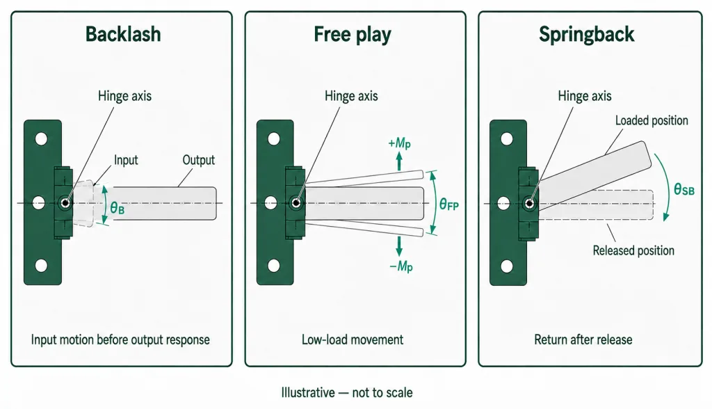
تصف مصطلحات «الارتداد» و«اللعب الحر» و«الارتداد الزنبركي» استجابات زاوية مختلفة، وينبغي تحديدها كل على حدة.
لا تستبدل هذه التعريفات بعبارات مثل “عدم الاهتزاز” أو “الارتداد الأدنى” أو “التحديد الدقيق للموضع”. فقد تصف هذه العبارات توقعات معينة، لكنها لا تحدد معيارًا قياسيًّا.
المفصلة ليست هي نظام تحديد المواقع بأكمله
عادةً ما تصف القيمة الواردة في الكتالوج مفصلةً في جهاز التثبيت الخاص بالمورد. أما المستخدم فيتعامل مع المجموعة الكاملة، لذا فإن مراجعة هندسة التطبيقات يجب أن تشمل الهيكل المحيط. وتقع بين هاتين النقطتين أدوات التثبيت الخاصة بالإنتاج، والدعامات، والجدران المشكلة، والألواح، والمقابض، والأجهزة المرفقة، والكابلات، وأحيانًا وصلة إضافية. ويمكن لكل واجهة أن تضيف فراغًا أو حركة مرنة.
وهذا يخلق تعارضًا هندسيًّا مألوفًا. فقد اجتازت المفصلة اختبارات عزم الدوران واختبارات الحركة المفقودة التي أجراها المورد. ومع ذلك، في الجهاز، لا تزال الشاشة تعود إلى وضعها الأصلي بشكل ملحوظ بعد تحريرها. ثم يُظهر القياس ثنائي الزاوية أن أجنحة المفصلة تتحرك مسافة ضئيلة جدًّا بالنسبة لبعضها البعض، في حين أن حامل التثبيت الرفيع يدور بالنسبة للهيكل. وكانت المواصفات الاسمية للمفصلة صحيحة. لكن التجميع لم يكن صلبًا بما يكفي لتلبية متطلبات تحديد الموضع.
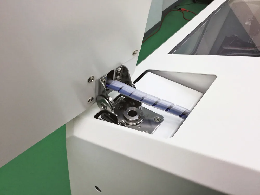
مجموعة مفصلات حقيقية مُركَّبة تُظهر الدعامة، ومثبتات التثبيت، وهيكل اللوحة، ومسار الكابلات التي تساهم في استجابة التموضع النهائية.
وقد يحدث العكس أيضًا. فقد يكشف التثبيت الصلب عن فراغ انعكاس داخلي يخفيه النموذج الأولي المرن مؤقتًا. وبمجرد تعزيز الدعامة، تصبح حركة المفصلة المتبقية أكثر وضوحًا. ولذلك، فإن اختبارات المكونات واختبارات التجميع متكاملة، وليست قابلة للتبادل.
افصل مقدار عزم الدوران عن خطأ تحديد الموضع. لا يزال يتعين دعم عزم الجاذبية. إذا لم يتم تحديد تلك القيمة بعد، فاستخدم حساب عزم الدوران المطلوب للمفصلة. قد تتمتع المفصلة بعزم دوران كافٍ مع حركة ضائعة كبيرة، أو قد تتمتع بضبط دقيق للموضع مع عزم تثبيت ضئيل جدًّا.
يجب على المسؤول عن القبول أن يقرر ما إذا كان المشروع يتحكم في المفصلة السائبة، أم في المجموعة الفرعية للمفصلة المركبة، أم في المنتج النهائي. فحد المكون يدعم عملية فحص المورد، بينما حد التجميع يحمي الأداء الوظيفي النهائي. وإذا تم تحديد حد واحد فقط، فيجب تحديد أيهما.
اختر نقطة الإسناد قبل الجهاز
لا تكون قراءة الزاوية ذات معنى إلا بين نقطتي مرجعية. فعبارة “قياس زاوية اللوحة” تترك المجال مفتوحًا بشأن ما إذا كان الفني يقوم بالقياس من منضدة العمل، أو قاعدة التثبيت، أو العلبة، أو جناح المفصلة، أو الهيكل. ويمكن أن يؤدي استخدام حامل متوافق إلى تغيير مواقع جميع نقاط المرجعية هذه بشكل مختلف.
بالنسبة للتجميع النهائي، عادةً ما يكون سطح الهيكل الثابت أو نقطة مرجعية محددة للتثبيت هي المرجع الثابت. يجب أن يكون الهدف الناتج موجودًا على الجزء الصلب من اللوحة المتحركة، في موقع محدد بعيدًا عن الحافة المرنة محليًّا. بالنسبة لاختبار المفصلة فقط، ضع أهدافًا مستقلة على الجناحين أو عناصر الإدخال والإخراج. سجل محور المفصلة لأن انتقال اللوحة خارج المحور قد يُخطئ في تفسيره على أنه دوران.
يمكن أن يكون مقياس الميل الرقمي كافياً في حالة التجميع البسيط الذي يعتمد على الجاذبية. وقد تكون هناك حاجة إلى مشفر دوار، أو جهاز تتبع بصري، أو هدف بصري، أو مستشعرات زاوية مزدوجة عندما تتحرك أداة التثبيت، أو عندما يكون النطاق المتوقع ضيقاً، أو عندما يتعين تسجيل زوايا الإدخال والإخراج في آن واحد. لا تُعد دقة الجهاز وحدها دليلاً على كفاءة الاختبار. كما يجب أن تشمل مراجعة نظام القياس تكرار التثبيت، ووضع الهدف، وضبط الصفر، وتأثير المشغل، وتوقيت جمع البيانات.
θFP = |θ(+Mp) − θ(−Mp)|
θSB(t) = |θ|تم التحميل − θصدر(t)|
s = r × θ
زاوية اللعب الحر θFP هو الفرق بين مواضع الإخراج في ظل عزم المسبار الموجب والسالب المحددين Mp. الارتداد θSB(ت) هو الفرق بين موضع التحميل وموضع التحرير في وقت القراءة المحدد t. الحركة الخطية s يساوي المسافة من محور المفصلة r مضروبًا في الزاوية θ بالراديان.
يمكن أن يسهل الإزاحة الخطية عند حافة اللوحة تصور المتطلبات، ولكن يجب أن تشمل نصف قطر القياس. فالخطأ الزاوي نفسه يؤدي إلى إزاحة أكبر للحافة في حالة اللوحات الأكبر حجمًا. لا تقارن الحدود المقيسة بالمليمتر عند أنصاف أقطار مختلفة دون تحويلها إلى أساس زاوي مشترك.
يجب أن يحدد الرسم نقطة الإسناد الثابتة، والهدف المتحرك، ومحور المفصلة، ونصف قطر القياس في حالة الإبلاغ عن الإزاحة الخطية، واتجاه الفتح الموجب. وتدخل هذه التفاصيل بشكل طبيعي في ورقة مواصفات المفصلة ورسمها; ؛ ولا ينبغي أن تقتصر على سلسلة رسائل البريد الإلكتروني فقط.
فصل حركة المفصلة عن الانثناء الهيكلي
يقوم أحد المستشعرات الموجودة على اللوحة برصد إجمالي الحركة. وهذه هي النتيجة الصحيحة لاختبار القبول الوظيفي، لكنها لا تحدد مصدر المشكلة. وعندما يتجاوز التجميع الحد المسموح به، يجب إضافة نقاط قياس بدلاً من استبدال الأجزاء عشوائياً.
| زوج القياس | ما يشمله | ما يمكنه عزلُه | الاستخدام النموذجي |
|---|---|---|---|
| ربط عنصر الإدخال بالمفصلة بعنصر الإخراج للمفصلة | مفصلة داخلية وواجهات تركيب فورية | اللعب الداخلي، واللعب الحر، وانحراف المفصلة المرن | تقييم الموردين وفحص البضائع الواردة |
| نقطة مرجعية الهيكل بالنسبة لورقة المفصلة الثابتة | حامل جانبي ثابت، ومثبتات، وجدار الغلاف | انزلاق التثبيت أو دوران هيكلي للجوانب الثابتة | أعمال تحديد الأسباب الجذرية في الجمعية |
| تحريك لوح المفصلة نحو الهدف المتمثل في اللوح الصلب | الوصلة الجانبية المتحركة، والكتيفة، وتثبيت الألواح | حركة التوصيل من جانب المخرج | أعمال تحديد الأسباب الجذرية في الجمعية |
| نقطة مرجعية الهيكل إلى الهدف المحدد للوحة التشغيلية | مجموعة البرامج المثبتة بالكامل | إجمالي خطأ تحديد الموقع الذي يلاحظه الجهاز | التحقق من التصميم والقبول النهائي |
تساعد علامات التتبع الموجودة على مفاصل أدوات التثبيت في الكشف عن الانزلاق. ويمكن لمقياس قراءة على حافة الدعامة أن يكشف عن حركة انتقالية قد يخفيها مستشعر الزاوية. كما يمكن أن تُظهر لقطات الفيديو أو مسارات المستشعرات المتزامنة ما إذا كانت الحركة تبدأ من المفصلة أو هيكل التثبيت أو اللوحة. وتُستخدم هذه الأجهزة الإضافية بشكل أساسي لأغراض التشخيص؛ حيث غالبًا ما يكون إجراء فحص مترابط أثناء الإنتاج أكثر بساطة.
كما يجب فحص الحمل المسبق والقيود. فقد تخزن المفصلتان اللتان لا تقع محاورهما على خط واحد طاقة مرنة عند شد أدوات التثبيت. ويمكن أن تولد حزمة الكابلات عزمًا عاكسًا يتغير مع الزاوية. ويمكن للمزلاج أو الموقف أن يضع حملًا مسبقًا على المجموعة المغلقة ويخفي الفراغ الحر حتى تتحرك اللوحة بعيدًا عنه. اختبر نطاق التشغيل الذي يضع فيه المستخدم اللوحة فعليًّا، وليس فقط عند موضع التوقف عند الإغلاق.
تسلسل اختبار تحديد المواقع الذي يمكن لمختبر آخر تكراره
يجب أن يحاكي الاختبار الحالة التي يكون فيها المطلب ذا أهمية. فالشاشة المثبتة عموديًا، والغطاء الأفقي، والمفصلة المثبتة على منضدة تتعرض جميعها لعزم خارجي مختلف. وإذا كان المنتج النهائي مزودًا بشاشة أو لوح زجاجي أو مقبض أو كابل أو حافة زخرفية، فيجب استخدام الكتلة ومركز الثقل المكافئين للإنتاج للتحقق من صحة التجميع.
- حدد العينة. سجل رقم القطعة، والإصدار، ورقم الدفعة أو الرقم التسلسلي، وعدد المفصلات، وإصدار الحامل، ومثبتات التثبيت، وحالة الشد، وحالة التشحيم أو الطلاء إن وجدت، واتجاه التركيب.
- عرّف مصطلح «التكييف». يرجى تحديد ما إذا كانت العينة جديدة، أو خضعت لعملية تشغيل سابقة، أو تعرضت لعوامل بيئية، أو خضعت لعملية إعادة تدوير مسبقة. وفي حال كانت عملية إعادة التدوير المسبقة مطلوبة، يرجى تحديد نطاق الزاوية، والسرعة، والحمل، وعدد العمليات.
- تثبيت ظروف الاختبار. سجل درجة الحرارة وأي ظروف أخرى معروفة بأنها تؤثر على آلية العمل. اترك العينة وجهاز التثبيت حتى يصلان إلى الحالة المطلوبة قبل ضبط الصفر.
- حدد المراجع. اضبط نقطة الإحداثيات الثابتة والهدف المتحرك على الصفر دون استخدام يد المشغل لتثبيت اللوحة في مكانها. تأكد من أن المستشعر والتركيبات لا تؤثر على الحركة.
- اقترب من الهدف من الاتجاه المحدد. قم بالتحرك بزاوية وسرعة محددتين مسبقًا بحيث تصل كل عينة بعد تعرضها لنفس ظروف الاحتكاك. لا تضع اللوحة مباشرةً عند الهدف وتعتبر ذلك مكافئًا.
- قم بقياس السلوك المحدد. بالنسبة للارتداد، قم بتسجيل انعكاس المدخلات واستجابة المخرج الأولى. بالنسبة للحركة الحرة، قم بتطبيق عزم المسبار المحدد (الموجب والسالب) دون إعادة وضع الآلية في موضعها عمدًا. بالنسبة للارتداد الزنبركي، قم بتسجيل الموضع تحت الحمل، ثم أزل المدخلات دون إحداث صدمة، وقم بتسجيل الموضع بعد التحرير في الوقت المحدد.
- كرر الحركة في الاتجاه المعاكس. قد تختلف نتائج الفتح والإغلاق بسبب اتجاه الاحتكاك، أو الجاذبية، أو رد فعل الكابل، أو الشكل الهندسي، أو التصميم غير المتماثل.
- الاحتفاظ بالقراءات الفردية. قم بالإبلاغ عن كل قيمة واتجاه قبل حساب أي متوسط. فقد يخفي المتوسط وحدة واحدة أو اتجاهًا واحدًا يتجاوز الحد الوظيفي.
إذا كان المشروع يحتاج أيضًا إلى منحنى كامل لعزم الدوران مقابل الزاوية، أو عزم الانطلاق، أو عزم التشغيل، أو نتيجة الثبات الساكن، فاستخدم الأداة المخصصة طريقة قياس عزم الدوران للمفصلة. قد يستخدم اختبار تحديد الموضع نفس جهاز التثبيت، لكن عتبات الاستجابة والزوايا المسجلة فيه تُستخدم لاتخاذ قرار قبول مختلف.
لا تستخدم «فحص اليد غير المحدد» كطريقة نهائية. يُعد التقييم البشري مفيدًا في الكشف عن أي إحساس غير مرغوب فيه. إلا أنه لا يجيد محاكاة لحظة الاختبار الدقيقة، أو سرعة الإطلاق، أو زمن البقاء، أو أول حركة قابلة للكشف في الناتج. يجب تحويل هذه الملاحظة إلى اختبار خاضع للرقابة قبل استخدامها لقبول قطع الإنتاج.
يجب أن تظهر «الاتجاه» و«الحمل» و«مدة البقاء» في النتيجة
إن الرقم المنفرد دون سياق الاختبار يخلق دقة زائفة. فقد ينتج عن نفس التجميع ارتداد مختلف بعد الفتح وبعد الإغلاق. وقد يتغير الفراغ الحر عندما تدفع الجاذبية اللوحة إلى أحد جانبي الفراغ. كما يمكن أن تتغير النتيجة مع تغير الزاوية المستهدفة، لأن مسار الكابلات أو هندسة الوصلات أو رافعة الدعامة تتغير خلال مسار الحركة.
على الأقل، قم بتسجيل الزاوية المستهدفة، واتجاه الاقتراب، والاتجاه، والحمل المرفق، وعزم الدفع أو عزم المسبار، وسرعة الحركة عند الاقتضاء، وطريقة التحرير، ووقت القراءة، وحالة التكييف، ودرجة الحرارة. بالنسبة للمنتجات متعددة المحاور، قم بتثبيت أو التحكم في المحاور الأخرى. إذا كان المنتج يستخدم مفصلتين، فاختبر الزوج المقصود والمسافة بينهما؛ حيث يمكن لجزأين متطابقين اسميًا أن يتشاركا الحمل بشكل غير متساوٍ عندما تكون محاورهما أو أسطح التثبيت غير متوازنة.
لا ينبغي الخلط بين القراءات الفورية والقراءات المستقرة. فالقراءة الفورية تعكس العودة المرنة، أما القراءة اللاحقة فقد تشمل الانحراف أو الاسترخاء أو الاستجابة الحرارية أو حركة التثبيت. وإذا كان كلاهما يؤثر على المستخدم، فيجب تحديد حدين منفصلين وطابعين زمنيين.
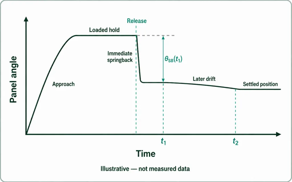
يُقاس الارتداد عند t1 بعد التحرير؛ أما الحركة اللاحقة حتى t2 فتُسجل بشكل منفصل باعتبارها انحرافًا.
زيادة عدد نقاط الاختبار لا تعني بالضرورة تحسين النتائج. اختر المنطقة المغلقة أو شبه المغلقة إذا كانت الوظيفة تتعلق بمحاذاة المزلاج، أو نطاق الرؤية العادي لشاشة العرض، أو زوايا التشغيل للغطاء. لا تضف نقاط النهاية إلا عندما تشكل نقاط التوقف، أو الشكل الهندسي، أو انتقالات الحمل خطرًا واضحًا. يجب أن تتوافق خريطة الاختبار مع المهمة المخصصة للمنتج.
اكتب المتطلبات بالدرجات، لا بالصفات
يجب أن تنبع الزاوية المسموح بها من وظيفة المنتج. فقد تكون الشاشة مقيدة بخط الرؤية أو استقرار اللمس. وقد يتعين أن يظل الغطاء ضمن نطاق آمن أو قابل للاستخدام بعد فتحه. وقد يتعين أن يحافظ غطاء المستشعر على محاذاة. وقد يتعين أن يتوافق الباب مع المزلاج أو مانع التسرب دون أن يقوم المزلاج بسحب الآلية إلى موضعها.
ابدأ بمجموع ميزانية تحديد المواقع الوظيفية. خصص جزءًا من تلك الميزانية لسلوك المفصلات، وجزءًا آخر للدعامات والمفاصل وانحراف الألواح والتباين في التصنيع وعدم اليقين في القياس. لا تخصص كامل هامش النظام للمفصلات لتكتشف بعد ذلك أن الهيكل الداعم لم يعد لديه أي هامش متبقي.
لا توجد زاوية عامة مفيدة يمكن تطبيقها على كل مشروع يعتمد على مفصل عزم الدوران. فالحد الصارم الذي لا يمكن قياسه أو الحفاظ عليه يزيد التكلفة دون أن يحمي الوظيفة. أما الحد المرن فيمكن أن يسمح بحركة مرئية، أو يؤدي إلى عدم استقرار التحكم، أو فشل في المحاذاة. يجب أن تحدد متطلبات المعدات هذا الحد؛ ومن ثم تُظهر بيانات قدرات المورد ما إذا كان التصميم عمليًّا أم لا.
مثال على بنية المتطلبات — استبدل كل متغير بقيم المشروع:
عند تركيب نسخة التجميع [R] في الاتجاه [O] وتحميلها بحمولة تعادل حمولة الإنتاج [L]، قم بضبط المخرج على [الزاوية المستهدفة] بعد الاقتراب من اتجاه [الفتح/الإغلاق] بزاوية لا تقل عن [زاوية الاقتراب] وبـ [نطاق السرعة].
اللعب الحر تحت تأثير عزم مسبار متناوب ±[Mp] يجب ألا يتجاوز [θFP] من القمة إلى القمة، مقاسة بين نقطة مرجعية الهيكل [D] والهدف الناتج [P].
بعد الحفاظ على الوضع المُحمَّل لمدة [th] وإزالة مدخلات التشغيل دون أن يترتب على ذلك أي تأثير، والارتداد عند [t1] يجب ألا يتجاوز [θSB1]. تغير زاوي إضافي عند [t2] يجب ألا يتجاوز [θD].
يجب ألا يتجاوز رد الفعل العكسي بعد الانعكاس [θB] عند رصد استجابة في الخرج عند عتبة [الزاوية/العزم] المحددة. يُطبق هذا الحد على كل عينة وعلى كل اتجاه محدد، ما لم ينص الرسم على خلاف ذلك.
تفصل هذه الصيغة بين مدخلات الاختبار واستجابة الحركة وقبول النتائج. كما أنها تمنع عبارة “عدم وجود تباطؤ” من أن تصبح عبارة لا يمكن اختبارها. فكل نتيجة لها عتبة وأساس قياس.
| حقل المواصفات | ما الذي يجب ذكره | ما أهمية ذلك |
|---|---|---|
| البند الخاضع للرقابة | مفصلة غير مثبتة، أو مجموعة فرعية مُركَّبة، أو منتج نهائي | يحدد التراخيات والهياكل المشمولة |
| سلوك الزوايا | الارتداد، واللعب الحر، والارتداد الزنبركي، و/أو الانحراف الموقوت | يمنع إدراج حركات مختلفة تحت تصنيف واحد |
| نقطة الإسناد والهدف | المرجع الثابت المسمى، ونقطة الخرج، والاتجاه الموجب | يتيح مقارنة القراءات بين الأجهزة والمختبرات |
| حالة التحميل | الكتلة، ومركز الثقل، والعزم الخارجي، والاتجاه حسب الاقتضاء | يحدد الانحراف المؤثر على الفراغات والأجزاء المرنة |
| سجل الطلبات | اتجاه الاقتراب، الزاوية المسبقة، السرعة، طريقة الإمساك والإفلات | يتحكم في تاريخ الاحتكاك والطاقة المرنة المخزنة |
| شرط الكشف | لحظة الفحص أو عتبة الاستجابة | يحول عبارة “بدء الحركة” إلى حدث موضوعي |
| مدة القراءة | وقت البقاء الفوري و/أو المحدد | يفصل بين الارتداد المرن والانحراف اللاحق |
| قاعدة القبول | الحد الأقصى لكل وحدة واتجاه، بالإضافة إلى أي متطلبات إحصائية | يمنع إخفاء العينات غير المطابقة في حساب المتوسطات |
إذا كان لا بد من التفاوض بشأن الحدود مع عدة موردين، فاحرص أولاً على أن تكون شروطهم وأحكامهم متطابقة في المعنى. إن مقارنة مواصفات المفصلات ذات العزم الثابت يوضح كيف يمكن أن تختلف تعريفات عزم الدوران والأدلة المسترجعة. ولتحديد دقة تحديد الموضع، أضف حقول نقطة الإسناد، وعتبة المجس، والاتجاه، والتوقيت الموضحة أعلاه.
تطبيق حدود الزوايا في عملية الفحص أثناء الإنتاج
يجب أن توفر العينات الأولية معلومات تفصيلية تتجاوز مجرد تحديد «النجاح» أو «الفشل». قم برسم بياني أو إعداد جدول للنتائج الفردية حسب العينة والزاوية والاتجاه. فهذا يكشف ما إذا كانت المشكلة تتمثل في انحراف ثابت، أو عدم تناسق اتجاهي، أو تباين واسع بين الوحدات، أو مشكلة زاوية موضعية، أو تغير بعد التكييف. وتكون المتوسطات وحدها غير كافية بشكل خاص عندما يلاحظ المستخدم أسوأ وحدة.
ينبغي أن يستخدم التحقق من التصميم على مستوى التجميع الأقواس والمثبتات وتعليمات الشد وكتلة الألواح ومركز الثقل ومسار الكابلات وموانع الحركة المخصصة للإنتاج الفعلي. ويمكن أن تثبت أداة التثبيت المُصنَّعة آليًّا سلوك المفصلات، مع إخفاء مدى توافق الهيكل المُختوم أو المصبوب. قم باختبار كليهما عندما تكون ميزانية تحديد موضع النظام محدودة.
يمكن اختزال فحص الإنتاج إلى مجموعة أصغر من النقاط المترابطة. على سبيل المثال، قد يكشف فحص الانعكاس المحدد عند زاوية التشغيل الأكثر حساسية عن وجود لعب حر، في حين أن فحص «الحركة والتحرير» الخاضع للرقابة يكتشف الارتداد. ولا يكون الفحص المختزل صالحًا إلا بعد أن تثبت الدراسات الهندسية أنه يستوفي المتطلبات الكاملة. لا تفترض أن الإحساس اليدوي الثابت أو قراءة عزم الدوران يمكن أن تكون بديلاً عن ذلك.
يجب أن يميز جهاز القياس بين تباين العملية وتباين القياس. استخدم دراسة لنظام القياس تتناسب مع المعدات والقرار المطلوب. وينبغي مراقبة تآكل التثبيتات، وصفر المستشعر، وموضع الهدف، وحمل المشبك، وتقنية المشغل. وإذا كان نطاق القبول ضيقًا مقارنةً بعدم اليقين في القياس المثبت، فيجب مراجعة الطريقة، أو إضافة نطاق أمان للقرار، أو إعادة النظر في المتطلبات قبل الإفراج عن المنتج.
رقم قياسي في دقة تحديد المواقع
- يمكن تتبع التعديلات التي تُجرى على القطع والرسومات والقوسات والتركيبات.
- يتم تحديد العنصر الخاضع للرقابة — سواء كان مفصلاً أو مجموعة فرعية أو منتجاً نهائياً — بشكل صريح.
- يتطابق كل من نقطة الإسناد والهدف والمحور والاتجاه الموجب مع الرسم.
- يتوافق الاتجاه، والحمولة المرفقة، ومركز الثقل، وحالة الكابل مع المنتج المقصود.
- يتم التحكم في اتجاه الاقتراب، ولحظة الاختبار، وسرعة الحركة، ووقت التثبيت، ووقت التحرير، ووقت القراءة.
- يتم الاحتفاظ بالقيم الفردية حسب العينة والزاوية والاتجاه.
- تم ربط شاشة الإنتاج بالاختبار الهندسي الشامل.
- نظام القياس قادر على دعم قرار القبول.
ما الذي تثبته في الواقع مزاعم «الارتداد» أو «الارتداد المرن»؟
تعد العبارات الواردة في ورقة البيانات الفنية، مثل “عدم وجود تباطؤ” أو “ارتداد زنبركي ضئيل”، دلالة تصميمية مفيدة، ولكنها لا تُعد بعد نتيجة لقبول المشروع. اسأل عن القياسات التي تم إجراؤها، والتركيبات والتوجيه، ونطاق الزاوية، والاتجاه، وعتبة الكشف، وعدد العينات وحالتها، وما إذا كانت العبارة تنطبق على كل وحدة على حدة أم على الخصائص النموذجية.
تتضمن حزمة النتائج الأكثر شمولاً تحديد رقم إصدار القطعة التي خضعت للاختبار، وتشمل الطريقة المتبعة، والمعدات المعايرة، والقراءات الأولية أو على مستوى الوحدة، وحدود القبول، والتصرف في النتائج غير المطابقة للمواصفات. وقد تُستخدم الشهادة الموجزة لدعم الدفعات الروتينية بعد إجراء المقارنة، لكنها لا يمكن أن تعيد بناء طريقة أصلية غير محددة.
كما لا يمكن لبيانات مكونات المورد أن تثبت مطابقة دعامة لم يقم المورد بتصميمها أو لوحة لم يقم المورد باختبارها. يجب تحديد المسؤوليات بشكل صريح: يتحكم مورد المفصلات في السلوك الذاتي للجزء في إطار التثبيت المتفق عليه؛ بينما يتحكم مصنع المعدات في هندسة التركيب ووضع المنتج النهائي. ويستند استكشاف الأعطال وإصلاحها المشترك إلى مجموعتي البيانات هاتين.
إذا لم يكن هناك نموذج حالي يتمتع بهامش تحديد الموضع الكافي، فيجب أن تبدأ المحادثة التالية بالتركيز على متطلبات النظام المقاسة بدلاً من طلب “مزيد من عزم الدوران”. قم بمراجعة الخيارات المتاحة في ضوء عزم الدوران المطلوب، والحدود القصوى، وواجهة التثبيت، وحدود التراخي في مفصل عزم الدوران، واللعب الحر، والارتداد المرن للمشروع.
تحديد متطلبات تحديد الموقع القابلة للقياس
لإجراء مناقشة مفيدة حول النموذج، يرجى توفير رسم اللوحة أو الشاشة، ومحور المفصلة وواجهة التثبيت، والكتلة المتحركة ومركز الثقل، ونطاق الزوايا المفيدة، وعزم الدوران المطلوب، والارتداد المسموح به/اللعب الحر/الارتداد الزنبركي، واتجاه الاقتراب، ونقطة الإسناد القياسية، واتجاه الحمل، ونتائج العينات المتاحة. تتيح هذه المعلومات مقارنة الأشكال الهندسية والمواصفات المرشحة دون اعتبار مصطلحي “مستقر” أو “دقيق” قيمتين عالميتين.
أسئلة حول دقة تحديد موضع مفصل العزم
هل من الممكن أن يكون هناك خطأ كبير في تحديد الموضع حتى في المفصلة ذات عزم الدوران العالي؟
نعم. فمقدار العزم ودقة تحديد الموضع هما خاصيتان منفصلتان. فقد تتمكن المفصلة من مقاومة عزم اللوحة المطلوب، مع وجود في الوقت نفسه خلوص انعكاس، أو حركة تركيب، أو ارتداد مرن يتجاوز الحد المسموح به في النظام.
هل تعني عبارة “عدم وجود تراجع” عدم وجود أي حركة زاوية على الإطلاق؟
لا يمكن ذلك دون تحديد عتبة اختبار محددة. فكل قياس له دقة محدودة وطريقة لاكتشاف استجابة المخرجات. اطلب معرفة جهاز القياس، والمدخلات المطبقة، وعتبة الاستجابة، ودقة التقرير التي تستند إليها هذه الادعاءات.
هل يتم دائمًا تصحيح الارتداد الزنبركي لمفصلة عزم الدوران عن طريق الضبط؟
لا. قد ينجم الارتداد عن الالتواء المرن في المفصلة، ولكنه قد ينجم أيضًا عن الأوراق، أو الدعامات، أو أدوات التثبيت، أو جدران الغلاف، أو اللوحة، أو رد فعل الكابل. قم بقياس جانبي الوصلة المشتبه بها قبل تغيير عزم الدوران.
هل ينبغي تحديد دقة تحديد الموضع بالدرجات أم بالمليمترات؟
عادةً ما تكون الدرجات أكثر وضوحًا عند وصف السلوك الدوراني. ويمكن أيضًا استخدام حد المليمتر عند نقطة وظيفية، لكن يجب أن يحدد الرسم المسافة بين هذه النقطة ومحور المفصلة. فبدون تحديد هذا نصف القطر، لا يمكن مقارنة النتائج الخطية المستمدة من مجموعات مختلفة.
هل ينبغي تطبيق معايير القبول الخاصة بالارتداد والارتداد المرن على كل وحدة على حدة أم على متوسط الدفعة؟
يجب تطبيق الحد الأقصى الوظيفي على كل وحدة ما لم تنص المواصفات المعتمدة على خلاف ذلك. ويمكن أن تدعم متوسطات الدُفعات وإحصاءات القدرة عملية التحكم في العملية، ولكن لا ينبغي أن تحجب أي مفصلة أو اتجاه فردي يتجاوز حد التموضع.