-
+86 13720060320
-
lanna@haitangs.com

كيفية قياس عزم الدوران للمفصل | إعداد الاختبار وطريقة إجرائه
المعرفة كيفية قياس عزم الدوران للمفصلة لا يقتصر الأمر على مجرد توصيل جهاز قياس وتسجيل أعلى قيمة. فقد تُظهر مفصلة عزم الدوران مقاومة مختلفة عند بدء الحركة، وأثناء الدوران، وعند انعكاس الاتجاه، وبعد التوقف، وعند زوايا مختلفة، وفي درجات حرارة مختلفة. كما تتغير النتيجة أيضًا عندما يكون التثبيت غير محاذي أو عند استخدام جهاز قياس القوة على ذراع الرافعة الخاطئ.
تتمثل المهمة الأولى في تحديد سلوك عزم الدوران الذي يتطلبه الرسم أو المواصفات. أما المهمة الثانية فهي تصميم جهاز تثبيت يتفاعل مع المفصلة دون إضافة احتكاك أو انثناء غير متحكم فيهما. أما المهمة الثالثة فهي التحكم في الاتجاه والزاوية والسرعة ووقت التوقف والتحضير المسبق ودرجة الحرارة ومعالجة البيانات، بحيث يتمكن مشغل آخر من تكرار النتيجة.
تبدأ هذه المقالة بعد أن يكون المشروع قد حدد مفصلة عزم الدوران أو مفصلة الاحتكاك باعتبارها الآلية محل الاهتمام. للاطلاع على مبدأ التشغيل العام ومجموعات المنتجات، انظر ما هو مفصل عزم الدوران.
حدود القياس: يُعد عزم الدوران المطلوب وعزم الدوران المقاس مسألتين هندسيتين مختلفتين. فالعزم المطلوب ينبع من الحمل الواقع على اللوحة ومن خصائصها الهندسية، أما العزم المقاس فهو المقاومة التي تولدها المفصلة أو المجموعة الكاملة في ظل ظروف اختبار محددة.
حدد عزم الدوران الذي تحتاج إلى قياسه في المفصلة
إن القيمة الواحدة التي تحمل تسمية “عزم الدوران عند المفصلة” تعتبر غير كاملة. قبل اختيار الجهاز، يجب تحديد أي جزء من منحنى الحركة سيصبح النتيجة التي سيتم الإبلاغ عنها.
| عزم الدوران الناتج | ما الذي يمثله | ما أهمية ذلك |
|---|---|---|
| عزم الإمساك | المقاومة المتوفرة عندما يكون المفصل أو اللوحة في حالة سكون في ظل الظروف المذكورة | يحدد ما إذا كان الحمل يظل في موضعه دون حدوث انحراف غير مقبول |
| عزم الدوران الانفصالي | القيمة القصوى المطلوبة لبدء الحركة بعد فترة توقف محددة | قد يؤدي الانفصال المفرط إلى الشعور بأن اللوحة عالقة قبل أن تقفز |
| عزم الدوران أثناء التشغيل | يتم تقييم المقاومة بعد بدء الحركة، وعادةً ما يتم تقييمها خلال نطاق زاوي محدد | يضبط الإحساس بالتحكم ويضمن حركة سلسة |
| عزم الدوران عند التشغيل | المقاومة المقاسة في اتجاه الفتح المحدد | قد يختلف عن الاتجاه المعاكس بسبب الشكل الهندسي أو تصميم الطريق أحادي الاتجاه |
| عزم الدوران عند الإغلاق | المقاومة المقاسة في اتجاه الإغلاق المحدد | يكشف عن عدم التماثل الاتجاهي والجهد المرتد |
| عزم الدوران الأقصى | أعلى قراءة صالحة داخل فترة الاختبار المحددة | مفيد في حالات الذروات الأولية، أو التداخل المحلي، أو مخاطر الحمل الزائد |
| متوسط عزم الدوران | القيمة المتوسطة على مدى نطاق زاوي محدد بعد استبعاد أي حالة عابرة محددة | مفيد لمقارنة الإنتاج عندما تكون منطقة التشغيل مستقرة |
| تغير العزم | التغيير حسب الزاوية أو الاتجاه أو العينة أو عمليات المسح المتكررة | يكشف عن حدوث تموجات، أو انزلاق متقطع، أو سوء محاذاة، أو عدم اتساق العملية |
لا تطلق على أعلى نقطة مسجلة مصطلح “عزم الثبات” ما لم تقم طريقة الاختبار فعليًّا بقياس المقاومة في حالة السكون. لا تذكر متوسطًا دون تحديد النطاق الزاوي. لا تقارن ذروة الفتح لدى مورد ما بالمتوسط المتحرك لدى مورد آخر.
إذا كان المشروع لا يزال بحاجة إلى تحديد عزم الدوران المستهدف بناءً على كتلة اللوحة ومسافة مركز الثقل، فقم بإكمال حساب متطلبات مفصل العزم قبل استخدام هذه الصفحة للتحقق من ناتج المفصلة.
اختر طريقة قياس عزم الدوران للمفصلة التي تتوافق مع القرار
| الطريقة | أفضل استخدام | القيد الرئيسي |
|---|---|---|
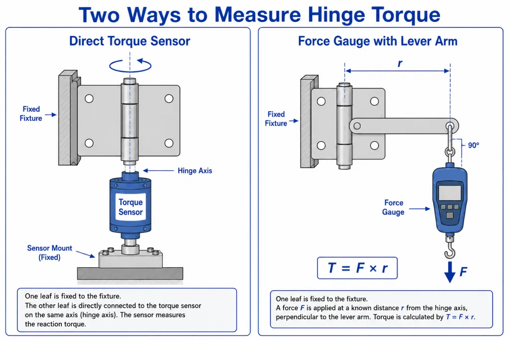
| مستشعر عزم الدوران المباشر | التوصيف الهندسي، ومنحنيات عزم الدوران مقابل الزاوية، والمقارنة الاتجاهية، والسرعة المتحكم فيها | يتطلب جهاز تثبيت دوارًا مضبوطًا بدقة ووصلات مناسبة |
| مقياس العزم أو جهاز قياس العزم | قياس المفصلات المدمجة على منضدة الاختبار عندما يمكن توصيل جهاز التثبيت مباشرةً بكلا الجانبين | قد تحتاج المقابض التجارية إلى محولات مخصصة لمنع الانزلاق أو الحمل خارج المحور |
| مقياس القوة ذو ذراع الرافعة المعروف | فحوصات منخفضة التكلفة، أو مفصلات كبيرة، أو ألواح مثبتة حيث يصعب إجراء التوصيل المباشر | تكون النتيجة دقيقة فقط عندما يتم التحكم في ذراع الرافعة العمودي واتجاه القوة |
| إجراء اختبار قوة الضغط على مقبض اللوحة بالكامل | التحقق مما يشعر به المستخدم عند استخدام الجهاز المُجمَّع | يشمل ذلك الجاذبية، والكابلات، والموانع التسرب، والانثناء في الحامل، وأنواع الاحتكاك الأخرى؛ ولا يُعتبر عزم الدوران هذا تلقائيًّا مقتصرًا على المفصلات فقط |
| جهاز تثبيت لتحديد ما إذا كان الإنتاج سيتم أم لا | إجراء فحص سريع بعد الموافقة على الطريقة الهندسية | عادةً ما توفر تفاصيل أقل، ويجب ربطها بطريقة التوصيف الخاضعة للرقابة |
استخدم مستشعر عزم الدوران المباشر عندما يعتمد القرار الهندسي على شكل منحنى العزم-الزاوية، أو على الفروق الطفيفة حسب الاتجاه، أو على المقارنة القابلة للتكرار بين العينات. واستخدم طريقة ذراع الرافعة عندما يكون التحكم في هندسة جهاز التثبيت أسهل من التحكم في الوصلة المحورية، وتكون الدقة المطلوبة متوافقة مع درجة عدم اليقين في القياس.
يُجيب اختبار اللوحة المُركبة على ما إذا كان المنتج النهائي يعمل بشكل صحيح من حيث الملمس والثبات. أما اختبار المنضدة الذي يقتصر على المفصلة، فيُجيب على ما تنتجه المفصلة. وقد يكون كلا الاختبارين ضروريين، لكن لا ينبغي الإبلاغ عنهما على أنهما نفس النتيجة.
تجميد العينة وظروف الاختبار قبل إجراء القياس
بالنسبة لـ التحقق من عزم الدوران واختبار الجودة, ، لا يمكن تعميم النتائج ما لم يتم التحكم في العينة والظروف. يجب أن يتضمن طلب الفحص تحديد الحقول التالية قبل القراءة الأولى.
| حقل الاختبار | ما الذي يجب تسجيله | التأثير على النتيجة |
|---|---|---|
| هوية المفصلة | الطراز، مراجعة الرسم، الدفعة أو المجموعة، المادة، التشطيب، وحالة الضبط | يمنع الخلط بين أنواع البناء أو الإعدادات المختلفة |
| حالة التجميع | المفصلة وحدها، وأقواس التثبيت، والمفصلات المزدوجة، واللوحة الكاملة، ومثبتات التثبيت، وحالة الشد | تزيد من أو تقلل من مقاومة الواجهة والامتثال الهيكلي |
| الاتجاه | في اتجاه عقارب الساعة/عكس اتجاه عقارب الساعة أو الفتح/الإغلاق باستخدام عرض مرجعي واضح | العديد من المفصلات ليست متماثلة تمامًا |
| نطاق الزاوية | زاوية البداية، وزاوية النهاية، ونوافذ القياس، ومناطق النهاية المستبعدة | قد يتغير العزم أثناء الدوران |
| سرعة الدوران | السرعة المحددة أو مدة الحركة خلال فترة الاختبار | قد يتأثر الاحتكاك وسلوك مواد التشحيم وجمع البيانات بمعدل التدفق |
| زمن البقاء | مدة الراحة قبل قياس الانفصال أو الثبات | يمكن أن يؤدي الاحتكاك الساكن وإعادة توزيع مادة التشحيم إلى تغيير ذروة الانطلاق |
| التحضير المسبق | عدد وعملية المسح قبل تسجيل البيانات؛ خاص بالمشروع | قد تستقر المفصلات الجديدة أو التي تم تعديلها مؤخرًا أثناء الحركة الأولى |
| درجة الحرارة | درجة حرارة العينة، وظروف الغرفة أو الحجرة، ومدة النقع | قد تتغير خصائص مواد الاحتكاك ولزوجة مواد التشحيم |
| الاتجاه والحمل الخارجي | اتجاه المحور، واتجاه الجاذبية، والكتلة المرتبطة به إن وجدت | قد تؤدي الجاذبية إلى زيادة أو نقصان في المقاومة المقاسة |
| التشحيم والتنظيف | الحالة التي تم توريدها بها وأي معالجة مسموح بها | قد يؤدي التنظيف أو إضافة مادة تشحيم إلى إبطال صحة المقارنة |
لا تحذف تفاصيل الإعداد “الثانوية” من التقرير. فقد يكون الفرق في مدة البقاء أو السرعة أو الزاوية أو الاتجاه أكبر من الفرق بين مفصلتين مقبولتين.
الأدلة الخاصة بالنموذج هي التي ترجح الكفة: عندما يحدد رسم المورد أو تعليمات الاختبار المعتمدة زاوية القياس أو السرعة أو الاتجاه أو درجة الحرارة أو التهيئة المسبقة، يجب استخدام تلك الشروط بدلاً من الاعتماد على الممارسات المعتادة في المختبر.
صنع جهاز قياس محوري لقياس العزم المباشر
يتطلب التثبيت الدوار المباشر تثبيت أحد جانبي المفصلة على إطار التفاعل، وربط الجانب الآخر بمستشعر عزم الدوران أو المحور الدوار المدفوع. ويجب أن ينقل جهاز التثبيت الدوران دون إجبار عمود المفصلة على التحرك جانبيًّا.
- المحور المشترك: قم بمحاذاة محور المستشعر، ووصلة التوصيل، ومحور المفصلة. يؤدي أي انحراف زاوي أو جانبي إلى زيادة الحمل على المحمل وظهور عزم دوران زائف.
- جانب رد الفعل المتشدد: تجنب تحرك اللوح الثابت أو الدعامة أو الغلاف تحت تأثير عزم الدوران.
- وصلة ذات تفاعل عكسي منخفض: استخدم محولًا يتناسب مع واجهة المفصلة دون أن ينزلق أو يتأرجح أو يضغط على الأجزاء المتحركة.
- لا يحدث احتكاك بين الأجزاء: احرص على خلو المنطقة من الأوراق والأقواس والمسامير وأغطية الحماية على طول نطاق الزاوية بأكمله.
- الموضع الصفري المحدد: حدد الزاوية المرجعية بحيث تستخدم بيانات الفتح والإغلاق نفس نظام الإحداثيات.
- الحماية من تجاوز المسافة: أوقف الآلة قبل أن يصل المفصل أو التثبيت إلى نقطة توقف هيكلية غير مقصودة.
- نطاق المستشعر المناسب: اختر نطاقًا مُعايرًا يتيح التحكم في عزم الدوران المتوقع دون الاقتراب من الحد الأقصى للحمل.
- أخذ العينات في ظروف مستقرة: قم بجمع بيانات كافية لتحديد ذروة البداية ومنطقة التشغيل دون استبعاد السلوك الصحيح.
قد تقلل الوصلات المرنة من إجهاد التجميع، لكنها قد تخزن طاقة الالتواء وتشوه الظاهرة الظاهرية للانفصال. أما الوصلات شديدة الصلابة، فيمكنها نقل اختلال المحاذاة مباشرةً إلى المستشعر والمفصلة. ويجب أن يحقق تصميم التثبيت التوازن بين المحاذاة والصلابة وسهولة التركيب.
قم بضبط الصفر للمستشعر بعد تجميع الجهاز في الوضع الابتدائي المحدد. إذا كان الجهاز نفسه يولد عزم دوران قابل للقياس، فقم بتحديد خصائص هذا العزم الأساسي عبر نفس نطاق الزوايا، وقم بتوثيق ما إذا كان يتم طرحه من نتيجة المفصلة أم لا.
قياس عزم الدوران للمفصلة باستخدام مقياس القوة وذراع الرافعة
يمكن لمقياس القوة قياس عزم الدوران للمفصلة عندما تُطبق القوة على مسافة عمودية معروفة من محور المفصلة. والعلاقة العامة هي:
الصيغة العامة: T = F × r⊥. إذا لم تكن القوة المؤثرة عمودية على ذراع الرافعة، فإن T = F × r × sin(α)، حيث T هي عزم الدوران، وF هي القوة المقاسة، وr هي المسافة من محور المفصلة إلى نقطة تأثير القوة، وα هي الزاوية بين ذراع الرافعة واتجاه القوة.
على سبيل المثال، القوة المقاسة البالغة 20 نيوتن والمطبقة بشكل عمودي على ذراع رافعة طوله 0.15 متر تمثل 3 نيوتن·متر. وهذا مثال توضيحي للصيغة، وليس قيمة مفصلية موصى بها.
التحكم في هندسة ذراع الرافعة
- قم بالقياس من محور المفصلة الفعلي إلى خط عمل القوة — وليس إلى حافة المقبض أو إلى برغي مناسب.
- احرص على أن تكون قوة المقياس عمودية على ذراع الرافعة عند زاوية القياس، أو استخدم تصحيح الجيب.
- استخدم رافعة صلبة لا تنحني بشكل ملحوظ تحت تأثير القوة المقاسة.
- تجنب انزلاق الخطاف أو طرف الدفع أو الشريط أو بكرة التلامس أثناء القراءة.
- سجل ما إذا كان المقياس يدفع أم يسحب، وكيف يرتبط اتجاه القوة بعملية الفتح أو الإغلاق.
الفصل بين الفحص اليدوي والقياس الخاضع للرقابة
يُعد جهاز القياس المحمول مفيدًا في استكشاف الأعطال وإجراء المقارنات الأولية، لكن سرعة المشغل واتجاه القوة والتقاط القيم القصوى قد تختلف. ويُحسّن الحامل الآلي أو المحور الخطي القابل للتحكم أو مسار السحب الموجه من قابلية التكرار عندما تُستخدم النتيجة للموافقة على العينة أو تحديد حدود الإنتاج.
عندما تتغير زاوية ذراع الرافعة بالنسبة لمقياس خطي ثابت، تتغير المسافة العمودية أيضًا. يمكن إما إجراء القياس عند زاوية محددة واحدة، أو إعادة ضبط موضع المقياس ليظل عموديًا، أو حساب التغيرات الهندسية. لا تستخدم ذراع رافعة ثابتًا واحدًا على طول قوس عندما لا يكون خط العمل ثابتًا.
قياس وتسجيل منحنى عزم الدوران مقابل الزاوية
قد تخفي القيمة القصوى الواحدة السلوك الذي يشعر به المستخدمون فعليًّا. قم بتسجيل عزم الدوران مقابل الزاوية عندما يحتاج المشروع إلى التمييز بين مقاومة الانطلاق، والحركة الثابتة، والقيم القصوى الموضعية، وتغيرات الاتجاه، أو التباين الزاوي.
- قم بتركيب العينة وتحديدها. تأكد من الطراز، والإصدار، والاتجاه، والوجه، وحامل التثبيت، وحالة الضبط.
- قم بتسخين النظام وضبطه على الصفر. اتبع إجراءات الجهاز وقم بضبط الصفر للتركيب المُجمَّع عند نقطة البداية المحددة.
- قم بتحضير المفصلة. قم بتمريره عبر الدورات والاتجاهات المعتمدة قبل إجراء عمليات المسح المسجلة؛ ويختلف العدد الدقيق باختلاف المشروع.
- قم بتطبيق شرط الانتظار. قم بتثبيت العينة عند زاوية البداية لمدة محددة عند قياس الانفصال.
- الدوران بالسرعة المحددة. قم بتسجيل عزم الدوران والزاوية بشكل مستمر أو في مجموعة محددة من المواضع.
- استبعاد المناطق غير الصالحة. لا تشمل قوة الشد الناتجة عن التثبيت، أو الاصطدام بمحدد المسافة، أو تشابك الكابل، أو الحركة خارج النطاق المسموح به.
- عكس الاتجاه في ظل الشرط المذكور. سجل قيم الافتتاح والإغلاق بشكل منفصل بدلاً من دمجهما.
- كرر عملية المسح. استخدم التكرارات المحددة في المشروع وتحقق مما إذا كانت النتيجة تستقر أم تستمر في التغير.
- احفظ المنحنى الأولي. احتفظ بالبيانات غير المُعالجة، والنتائج المحسوبة، وهوية العينة، وظروف الاختبار.
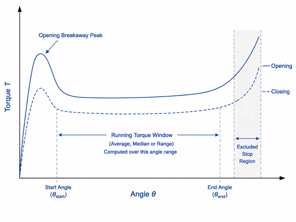
حدد نوافذ البيانات قبل مراجعة النتيجة. على سبيل المثال، قد تكون «قمة الانطلاق» هي أول قمة صالحة بعد بدء الحركة، في حين قد يكون «عزم الدوران أثناء التشغيل» هو المتوسط أو الوسيط عبر نطاق زاوية مركزية محدد. ويختلف التعريف الدقيق باختلاف المشروع.
لا تقم بإدراج محدد النهاية الميكانيكي ضمن نطاق عزم الدوران العادي. يقيس تأثير التوقف مسار الحمل عند نقطة التوقف والتثبيت، وليس سلوك الاحتكاك للمفصلة.
قياس عزم الثبات وعزم الانحراف بشكل منفصل
لا يُثبت عزم الدوران تلقائيًّا أن اللوحة ستظل ثابتة. فقد تتحرك المفصلة بمقاومة مقبولة، ومع ذلك تنحرف تحت تأثير عزم خارجي مستمر. وعلى العكس من ذلك، قد تقاوم المفصلة الحركة الساكنة بشكل جيد، لكنها تتميز بقيمة ذروة انطلاق عالية تجعل إعادة وضعها في موضعها أمرًا صعبًا.
يجب أن يحدد اختبار التحمل الثابت زاوية المفصلة، واتجاه العزم المطبق، والحمل الخارجي، ومدة التثبيت، والحركة الزاوية المسموح بها، ودرجة الحرارة، وما إذا كان الاختبار يبدأ بعد الفتح أم الإغلاق. وتعد هذه التفاصيل مهمة لأن المفصلة قد تستقر بشكل مختلف اعتمادًا على الاتجاه الذي يتم من خلاله الوصول إلى الوضع.
| طريقة الاختبار الثابت | ما الذي يقيسه هذا الجهاز؟ | عنصر تحكم مهم |
|---|---|---|
| عزم الدوران المطبق دون أي حركة مسموح بها | أدنى عزم دوران خارجي يمكن للمفصلة مقاومته عند زاوية محددة | حدد مدة البقاء والحركة الزاوية التي تُعتبر فشلًا |
| لحظة اللوحة المعروفة ومراقبة الانجراف | ما إذا كان التجميع الكامل لا يزال ضمن نطاق الزاوية المسموح به | تسجيل كتلة اللوحة، ومركز الثقل، واتجاه المحور، والكابلات، واتجاه الاقتراب |
| عزم الدوران التزايدي حتى حدوث الحركة | عتبة الإفراج الثابت بعد فترة انتظار محددة | قم بتطبيق عزم الدوران تدريجيًّا، وافرق بين الحركة الحقيقية واستجابة التثبيت |
| مقارنة بين ثبات الوضع قبل التكييف وبعده | التغير في الأداء الثابت بعد التعرض لدورات متكررة أو تغيرات في درجة الحرارة أو البيئة | استخدم نفس الزاوية والاتجاه والحمل ومدة البقاء وطريقة القياس |
عند استخدام مقياس القوة، قم بتطبيق القوة على ذراع الرافعة العمودي المعتمد وحافظ على هذه القوة لمدة محددة. لا تستخدم قراءة الذروة المؤقتة كدليل على الاستمرار في الحفاظ على القوة. إذا سُمح للوحة بالتحرك قليلاً، فحدد الحد الأقصى للانحراف الزاوي وفترة المراقبة.
غالبًا ما يُعد اختبار اللوحة المحملة الدليل الوظيفي الأكثر وضوحًا، لكنه يمثل التجميع الكامل. أما الاختبار الساكن للمفصلة وحدها فهو الأفضل عندما يتطلب الرسم تحديد حد عزم الدوران للمكون. استخدم كلا الاختبارين عندما يتعين على الشركة المصنعة الأصلية (OEM) الموافقة على المفصلة وعلى أداء المعدات النهائي.
لا تخلط بين المقاييس الثابتة والديناميكية: قد يكون هناك ارتباط بين عزم الانفصال، وعزم التثبيت الساكن، وعزم التشغيل، وانحراف اللوحة؛ لكن لا يمكن استبدال أي منها بآخر دون وجود علاقة متبادلة مثبتة.
توحيد الوحدات، وقواعد الإشارات، والدقة المُبلغ عنها
قد تُفسر بيانات العزم تفسيرًا خاطئًا حتى لو كان الاختبار نفسه سليمًا. يجب ذكر الوحدة، وقواعد تحديد الاتجاه، والمنظور المرجعي، وزاوية الصفر، وقواعد تحديد الإشارة في كل رسم بياني وجدول نتائج.
| حقل الإبلاغ | الممارسات الموصى بها | تجنب |
|---|---|---|
| وحدة العزم | استخدم وحدة قياس أساسية واحدة للمشروع، وعادةً ما تكون N·m أو N·cm، وحدد أي قيمة تم تحويلها | الخلط بين الوحدات kgf·cm و lbf·in و N·cm و N·m دون التحكم في التحويل |
| الاتجاه | حدد عزم الدوران الموجب والسالب من منظور الرسم أو استخدم خيارات «فتح» و«إغلاق» | الكتابة في اتجاه عقارب الساعة أو عكس اتجاه عقارب الساعة فقط دون تحديد جانب مرجعي |
| الزاوية | تحديد الموضع الصفر، والدوران الموجب، ونطاق القياس الصحيح | بافتراض أن كل مشغل يستخدم نفس الوضع المغلق |
| الدقة | لا تُدرج في التقرير سوى الأرقام التي تدعمها دقة المستشعر وقدرات الطريقة | نشر أرقام عشرية زائدة توحي بدقة زائفة |
| تسميات المنحنيات | تحديد العينة ورقم المسح واتجاهه ودرجة الحرارة والسرعة والتاريخ | حفظ المنحنيات المجهولة التي لا يمكن تتبعها حتى المفصلة |
تشمل العلاقات المفيدة بين الوحدات ما يلي: 1 نيوتن·متر = 100 نيوتن·سم، و1 رطل-قوة·بوصة ≈ 0.113 نيوتن·متر، و1 كيلوغرام-قوة·سم ≈ 0.0981 نيوتن·متر. يجب التعامل مع القيم المحولة على أنها نتائج مشتقة، مع الاحتفاظ بالوحدة الأصلية المقاسة في السجل الأولي.
بالنسبة للمفصلات أحادية الاتجاه أو غير المتماثلة، قد يكون من المفيد استخدام منحنى عزم الدوران-الزاوية المُشار إليه بعلامة. أما بالنسبة لمشغلي خطوط الإنتاج، فقد تكون علامات الفتح والإغلاق أكثر وضوحًا. اختر أسلوبًا واحدًا وقم بتطبيقه بشكل متسق في جميع أنحاء الرسم، والتجهيزات، والبرمجيات، والتقرير، ومعايير القبول.
الفصل بين عزم الدوران للمفصلة وعزم الدوران التشغيلي للمجموعة الكاملة
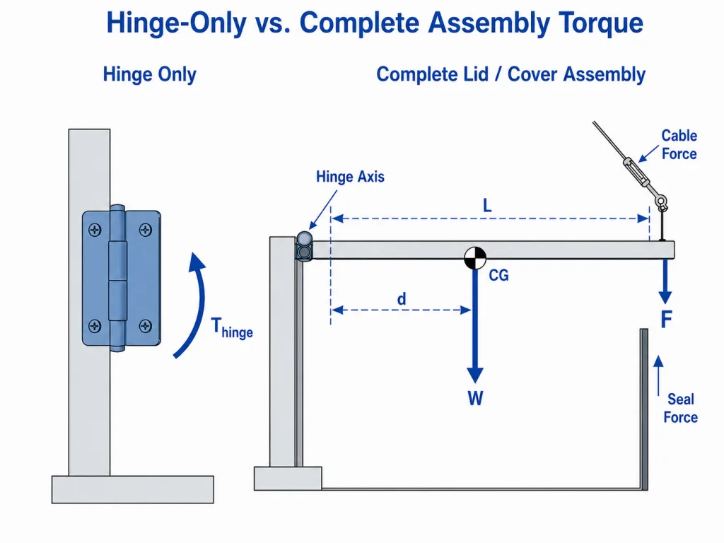
عند قياس المفصلة على غطاء أو واجهة عرض أو باب محمل، فإن الجهاز عادةً ما يلتقط عوامل أخرى غير المفصلة نفسها. ويمكن أن يشمل عزم الدوران المقاس للمجموعة مقاومة المفصلة، وعزم الجاذبية، وقوة الكابل، وضغط مانع التسرب، وتداخل المزلاج، واحتكاك المحمل، وتشوه الدعامة.
علاقة التجميع: Tالمقاسة = Tمفصلة + Tالجاذبية + Tالكابلات/الأختام + Tواجهات أخرى. تعتمد إشارة كل مساهمة على الاتجاه والزاوية.
| السلوك الملحوظ | مساهم محتمل | كيفية فصله |
|---|---|---|
| يتغير العزم تغيرًا كبيرًا مع الزاوية | الجاذبية، أو مسار الكابل، أو قوة الزنبرك، أو تغير شكل مانع التسرب | قياس المفصلة وحدها أو تحديد خط أساس غير مرتبط بالمفصلة |
| منحنيات البداية والنهاية متباعدة | الجاذبية، أو تباطؤ الحشية، أو مقاومة المزلاج، أو التصميم المتعمد للمفصلة أحادية الاتجاه | عكس الاتجاه أو إزالة المساهمين الخارجيين واحدًا تلو الآخر |
| الذروة المحلية عند زاوية معينة | تشابك الكابل، أو ملامسة الحامل، أو تداخل الموقف، أو احتكاك وحدة الإضاءة | افحص المجموعة أثناء مراجعة منحنى عزم الدوران وزاوية الدوران |
| عزم الدوران عند التركيب أعلى من عزم الدوران على منضدة الاختبار | اختلال محاذاة المحاور، أو تشوه أدوات التثبيت، أو التواء الألواح، أو واجهات إضافية | قم بفك أو إعادة تثبيت المكونات بشكل منهجي دون تغيير إعدادات المفصلات |
| تظل اللوحة ثابتة حتى عندما يبدو عزم الدوران المقاس للمفصلة منخفضًا | التوازن المضاد، أو الدعم الزنبركي، أو الوضع الملائم لمركز الثقل، أو المفصلات المتعددة | حساب وقياس مسار الحمل بالكامل |
استخدم المجموعة الكاملة للتحقق من الجهد الذي يبذله المستخدم ومن ثبات اللوحة. استخدم جهاز التثبيت المخصص للمفصلة فقط للتحقق من عزم الدوران الناتج عن المفصلة نفسها. لا تقم بطرح قيمة الجاذبية النظرية دون التأكد من الكتلة الفعلية ومركز الجاذبية واتجاه المحور والزاوية.
قياس مفصلات العزم المزدوجة أو المتعددة كنظام واحد
يمكن اختبار المفصلات المتعددة بشكل فردي، أو معًا في جهاز تثبيت مشترك، أو على اللوحة الكاملة. وتقدم كل طريقة إجابة على سؤال مختلف.
| تكوين الاختبار | ما يكشفه ذلك | ما قد يفوته |
|---|---|---|
| كل مفصلة على حدة | عزم الدوران لكل وحدة، والاتجاه، وشكل المنحنى، والتباين بين القطع | عدم تطابق المحاور وتقاسم الأحمال في اللوحة النهائية |
| زوج متطابق في تثبيت صلب | العزم والتزامن معًا في ظل هندسة خاضعة للتحكم | مرونة اللوحة، والمثبتات الفعلية، ومطابقة الغلاف للمواصفات |
| مجموعة اللوحة الكاملة | الجهد الذي يبذله المستخدم، والتثبيت، واللف، وتأثيرات الكابل، ومحاذاة التركيب | مساهمة كل مفصلة على حدة ما لم يتم إجراء قياسات إضافية |
لا تفترض أن عزم الدوران المجمَّع يساوي بالضبط المجموع الحسابي لقيمتي الكتالوج. فقد تؤدي تفاوتات التركيب، وصلابة الحامل، وخطأ المحور، واختلاف أشكال المنحنيات إلى إحساس بعدم التوازن في الزوج أو إلى ظهور قمم محلية.
إذا حدد الرسم عزم الدوران الإجمالي للتجميع، فيجب توضيح ما إذا كان لكل مفصلة حد فردي أيضًا. تساعد الحدود الفردية على منع تحمل إحدى المفصلات الجزء الأكبر من المقاومة، في حين يبدو العزم الإجمالي مقبولًا.
تحليل نتائج «الانفصال» و«الجري» و«الاحتفاظ بالكرة» و«الاتجاه»
| المقياس المُبلغ عنه | التعريف الموصى به في طريقة الاختبار | الأخطاء الشائعة في إعداد التقارير |
|---|---|---|
| عزم الدوران الانفصالي | أول ذروة صالحة بعد بدء الحركة عقب فترة التوقف المحددة | الإبلاغ عن تأثير على جدول المباريات أو ارتفاع مفاجئ في البيانات |
| عزم الدوران أثناء التشغيل | المتوسط أو الوسيط أو النطاق على مدى نطاق زاوي محدد بالسرعة المذكورة | استخدام القوس بأكمله، بما في ذلك نقاط البداية والنهاية |
| فرق السعر عند الفتح/الإغلاق | منحنيات منفصلة أو الفرق المحسوب عند الزوايا المتطابقة | دمج الاتجاهين في قيمة واحدة |
| تذبذب العزم | التباين من القمة إلى القمة أو أي تباين آخر معتمد داخل النافذة الجارية | وصف كل تغيير في الزاوية بأنه عيب دون أي حدود |
| سلوك الاحتفاظ | التوازن الانجرافي أو التوازن الساكن تحت تأثير عزم خارجي محدد وفترة سكون | استخدام القيمة الجارية كدليل تلقائي على التثبيت الثابت |
| التكرار | الاختلاف بين عمليات المسح المتكررة على عينة واحدة | الجمع بين التباين داخل العينة والتباين بين الأجزاء |
| قابلية التكرار | الاختلافات بين المشغلين أو التجهيزات أو الأجهزة أو المختبرات | بافتراض أن قابلية التكرار لدى مشغل واحد تمثل الطريقة بأكملها |
احتفظ بمنحنيات عزم الدوران وزاوية الدوران الأولية من أجل المراجعة الهندسية. يُعد الجدول الملخص مفيدًا للحصول على الموافقة، لكن المنحنى غالبًا ما يكشف عن حالات عدم المحاذاة، أو ظاهرة «الالتصاق والانزلاق»، أو التداخل الموضعي، أو السلوك المتأثر بالاتجاه، وهي أمور يخفيها الرقم الواحد.
عند استخدام عمليات التنعيم أو التصفية، يجب حفظ البيانات الأولية وبيان الخوارزمية المستخدمة. فقد تؤدي التصفية المفرطة إلى إزالة القمم المنفصلة الحقيقية أو تموجات عزم الدوران، في حين أن أخذ العينات غير الكافية قد يؤدي إلى عدم رصدها.
التحكم في المصادر الرئيسية لخطأ قياس عزم الدوران في المفصلات
| مصدر الخطأ | التأثير على نتيجة عزم الدوران | التحكم |
|---|---|---|
| معايرة المستشعر وانحراف الصفر | خطأ ثابت في الإزاحة أو المقياس | استخدم جهازًا معايرًا مناسبًا وتحقق من نقطة الصفر قبل إجراء الاختبار |
| نطاق المستشعر ودقته | تصبح القراءات المنخفضة مشوشة أو مقربة؛ وقد يؤدي الحمل الزائد إلى تلف المستشعر | قم بمطابقة النطاق مع عزم الدوران المتوقع وهامش الحمل الزائد المعتمد |
| طول ذراع الرافعة | الخطأ التناسبي المباشر في الحساب القائم على القوة | قم بقياس المسافة العمودية من المحور الحقيقي |
| زاوية القوة | يتم المبالغة في النتيجة في حالة استخدام القوة الكاملة دون تصحيح الجيب | اجعل القوة عمودية أو احسب الخصائص الهندسية |
| اختلال محاذاة المحور | يضيف الحمل الجانبي، واحتكاك المحامل، والقمم الزائفة | استخدم ميزات تحديد المواقع وتحقق من محاذاة الكابلات المحورية |
| التوافق بين الأجزاء المتصلة أو اللعب | يؤخر الحركة ويشوه الانفصال | استخدام مسار تحميل صلب ذي تباطؤ منخفض وتحديد خصائص سلوك التثبيت |
| تباين السرعة ومدة البقاء | يغير استجابة الاحتكاك الساكن والديناميكي | أتمتة الحركة أو استخدام إجراء خاضع للرقابة |
| درجة الحرارة | يؤثر على سلوك مواد التشحيم ومواد الاحتكاك | قم بتحضير العينة وتسجيل درجة الحرارة |
| أخذ العينات من البيانات وتصفيتها | تتجاهل القمم أو تخلق انسيابية مصطنعة | تحديد إعدادات الاستحواذ والمعالجة |
| تقنية المشغل | التغييرات تُفرض على الاتجاه، والمعدل، والقيمة الصفرية، والقيمة القصوى المحددة | استخدم الأدلة أو التدريب أو حاملًا آليًّا |
يجب ألا تتضمن النتيجة عددًا من المنازل العشرية يفوق ما يمكن أن تدعمه الأداة، والتركيبات، والهندسة، والطريقة. ويجب أن تشمل حدود الإنتاج القدرة العملية على القياس، وليس فقط التفاوت المسموح به للمنتج.
عندما يكون تفاوت عزم الدوران قريبًا من خطأ القياس المتوقع، يجب تحسين جهاز التثبيت والطريقة المتبعة قبل تشديد حدود المنتج. وإلا، فقد تفشل المفصلات الجيدة وقد يتم قبول المفصلات المعيبة، اعتمادًا على إعدادات الجهاز.
استكشاف أخطاء اختبار عزم الدوران في المفصلات وإصلاحها
| مسألة اختبارية | السبب المحتمل | الإجراءات التصحيحية |
|---|---|---|
| تتغير القمة المنفصلة مع كل مسح | يختلف التمدد، أو تنزلق التركيبات، أو لا تزال المفصلة في مرحلة الاستقرار، أو لا توجد انحرافات | التحكم في مدة البقاء، وفحص المحولات، والتحضير المسبق، وإعادة الضبط إلى الصفر |
| يرتفع العزم بالقرب من أحد طرفي نطاق الحركة | تلامس المثبت، أو شد الكابل، أو تعشيق الموقف، أو خطأ في المحور | افحص الغلاف المتحرك واستبعد منطقة التوقف |
| نتيجة الافتتاح مستقرة، لكن نتيجة الإغلاق متقلبة | رد الفعل العكسي، أو تأثير الانعكاس، أو تباطؤ الكابل، أو سلوك الآلية أحادية الاتجاه | تحديد إجراءات التراجع وفحص مسار الحمل العكسي |
| يُحصل المشغلان على قيم مختلفة | يختلف كل من السرعة اليدوية، وزاوية القوة، واختيار القيمة القصوى، أو موضع الذراع | استخدم الأدلة، والحركة التلقائية، وقاعدة نافذة البيانات المكتوبة |
| تتعارض نتائج المستشعر المباشر وذراع الرافعة | نصف قطر غير صحيح، أو زاوية قوة غير صحيحة، أو وزن فارغ للمستشعر غير صحيح، أو ظروف اختبار مختلفة | مواءمة الشكل الهندسي والوحدات والاتجاه والسرعة ومدة التوقف وحالة العينة |
| الوحدة المُركَّبة أكثر صلابة بكثير | تشوه الحامل، أو عدم توازي المحاور، أو الحمل المسبق للمثبتات، أو الختم، أو الكابل، أو التواء اللوحة | افصل المساهمين في «المفصل فقط» عن المساهمين في «المجموعة» |
| يتطابق عزم الدوران المطلوب المحسوب، لكن اللوحة تنحرف | القيمة المقاسة ليست عزم الدوران الثابت، أو أن هندسة الحمل غير صحيحة | التحقق من حساب المتطلبات وإجراء اختبار الاحتفاظ المحدد |
| ينخفض عزم الدوران بعد الضبط | الإعداد غير مقفل، أو أن التحميل المسبق قد استقر، أو أن الآلية قد تم تعديلها بشكل يخالف التعليمات | اتبع إجراءات الضبط وإعادة الفحص الخاصة بكل طراز |
يجب أن تتم عملية استكشاف الأخطاء وإصلاحها في القياس عن طريق تغيير متغير واحد في كل مرة. فقد يؤدي استبدال المفصلة قبل فحص جهاز التثبيت إلى إخفاء مشكلة في الإعداد، مما يؤدي إلى استنتاجات غير متسقة عبر العينات.
الفصل بين التوصيف الهندسي وفحوصات عزم الدوران في مرحلة الإنتاج
ينبغي أن يكشف الاختبار الهندسي عن السلوك الكامل المطلوب للموافقة على التصميم. أما الاختبار الإنتاجي فينبغي أن يكتشف التباينات غير المقبولة بسرعة دون الحاجة إلى إعادة تنفيذ كل خطوة من خطوات تحديد الخصائص.
| مستوى الاختبار | المخرجات النموذجية | عنصر التحكم المطلوب |
|---|---|---|
| التوصيف الهندسي | منحنيات الفتح والإغلاق الكاملة، والانفصال، والنوافذ المتحركة، والتباين الزاوي، ومقارنات درجات الحرارة أو الظروف | جهاز اختبار خاضع للرقابة، وبيانات أولية قابلة للتتبع، وعمليات معالجة محددة، وسجل كامل للعينة |
| الموافقة على العينة | المقاييس المعتمدة للمفصلات المخصصة للإنتاج والتجميع الكامل | مراجعة المخطط، ودفعة المورد، ومراجعة القوالب، ونطاقات القبول، والارتباط بالتطبيق |
| فحص الإنتاج | نقطة عزم الدوران المحددة، أو النافذة الزاوية، أو نتيجة «مقبول/غير مقبول» | التوافق المؤكد مع المنهج الهندسي، وتعليمات المشغل، وفحوصات أجهزة القياس، وخطة الاستجابة |
لا تقم بتحويل اختبار قوة المقبض العملي في مرحلة الإنتاج إلى تعريف هندسي ما لم يتم إثبات العلاقة مع عزم الدوران للمفصلة. ولا يكون للاختبار السريع قيمة إلا عندما يستبعد نفس المشكلات الوظيفية التي تستبعدها الطريقة المعتمدة.
في حالة المفصلات القابلة للتعديل، لا يُعد قياس الإعداد المعتمد بديلاً عن الإجراء المتبع لتغيير هذا الإعداد وتثبيته. استخدم الدليل المنفصل الموجود في كيفية ضبط مفصلة عزم الدوران عندما تتطلب نتيجة القياس تصحيحًا.
سيناريو هندسي مركب: غطاء الوصول إلى الأجهزة
مثال هندسي: هذا سيناريو هندسي مركب تم إنشاؤه لشرح منطق القياس. وهو ليس سجلاً لمشروع عميل ولا ادعاءً يتعلق باختبار منتج.
تتلقى إحدى شركات تصنيع المعدات الأصلية (OEM) عينتين من مفصلات العزم ذات التصنيف الاسمي نفسه. وكلاهما يُستخدم لتثبيت غطاء صغير للوصول إلى الأجهزة، لكن إحداهما تعمل بسلاسة، بينما تتعثر الأخرى قبل أن تتحرك. يستخدم الاختبار الأول مقياس قوة محمول باليد عند حافة الغطاء، ويقوم بتسجيل القوة القصوى فقط. تختلف النتائج لأن المشغل يغير زاوية السحب وسرعته، كما أن مركز ثقل الغطاء يضيف عزمًا متغيرًا.
تقوم الهندسة بفصل الأسئلة عن بعضها. يُقاس المفصل أولاً بمفرده باستخدام مستشعر عزم دوران محوري. تحدد هذه الطريقة اتجاه الفتح والإغلاق، وزاوية البداية، ومدة التوقف، والسرعة، والتحضير المسبق، ونطاق عزم الدوران المركزي أثناء التشغيل. ويُظهر المنحنى أن كلا العينتين تتمتعان بعزم دوران مشابه أثناء التشغيل، لكن إحداهما تسجل ذروة انطلاق أعلى.
ثم يتم اختبار الغطاء بالكامل باستخدام مقياس قوة موجه بذراع رافعة عمودي ثابت. ويشمل هذا الاختبار الثاني عوامل الجاذبية، والكابلات، وصلابة الدعامة، ونقطة التلامس مع المستخدم. وتوفر المفصلة الأكثر سلاسة الإحساس التشغيلي المفضل دون المساس بأداء التثبيت المطلوب.
لا يعتمد الرسم المعتمد على رقم اسمي واحد. بل يحدد حدودًا منفصلة للانفصال والتشغيل، والاتجاه، ونطاق الزاوية، ودرجة الحرارة، ومرجع جهاز الاختبار. ويستخدم الإنتاج فحصًا مرتبطًا أقصر، في حين تظل طريقة العزم-الزاوية الكاملة هي المرجع الهندسي.
استخدم طريقة عزم الدوران نفسه قبل وبعد اختبار الدورة
لا يكون الاحتفاظ بالعزم ذا مغزى إلا عندما تستخدم القياسات قبل وبعد التجربة نفس حالة العينة، والاتجاه، ونطاق الزاوية، والسرعة، ومدة التوقف، ودرجة الحرارة، وجهاز التثبيت، ونافذة البيانات، وقاعدة المعالجة. وقد يؤدي تغيير الطريقة إلى إظهار ما يبدو أنه تدهور في المنتج أو إخفاء التدهور الفعلي.
لا تحدد هذه المقالة عدد الدورات المطلوب أو التغير المسموح به في عزم الدوران. وتعود هذه القرارات إلى دليل عمر دورة مفصل العزم والاحتفاظ بالعزم. وينبغي أن تشير خطة اختبار العمر التشغيلي تلك إلى طريقة القياس التي تم تطويرها هنا.
إذا تم قياس المفصلة وهي ساخنة مباشرة بعد إجراء دورة اختبار سريعة، فيجب تسجيل هذه الحالة بشكل منفصل عن النتيجة التي تم الحصول عليها عند درجة حرارة الغرفة المستقرة. وقد يكون كلاهما مهمين، لكنهما يجيبان على أسئلة مختلفة.
قائمة مراجعة لقياس عزم الدوران في المفصلات
قياس عزم الدوران للمفصلة — قائمة مراجعة فنية
------------------------------------------------
هدف القياس
[ ] تحديد الناتج المطلوب: الثبات / الانفصال / التشغيل / الفتح / الإغلاق
[ ] توضيح ما إذا كانت النتيجة تتعلق بالمفصلة فقط أم بالمجموعة الكاملة
[ ] الموافقة على تعريف القيمة القصوى أو المتوسطة أو الوسيطة أو النطاق أو الانحراف
[ ] فصل حساب عزم الدوران المطلوب عن الناتج المقاس

العينة
[ ] تم تسجيل طراز المفصلة، والإصدار، والدفعة، والتشطيب، وحالة الضبط
[ ] تم تحديد ما إذا كانت مفصلة مفردة، أو زوج متطابق، أو مجموعة كاملة
[ ] تم تسجيل أدوات التثبيت، والأقواس، واللوحة، والكابلات، والموانع، والحمل الخارجي
[ ] تم التحكم في التشحيم، والتنظيف، والتحضير المسبق

الأجهزة والتجهيزات
[ ] نطاق مستشعر عزم الدوران أو مقياس القوة مناسب
[ ] تم التحقق من المعايرة وحالة الصفر
[ ] محور المفصلة ومحور المستشعر متوازيان
[ ] الجانب الثابت صلب والجانب المتحرك لا ينزلق
[ ] تم فحص احتكاك التثبيت، والارتداد، والتلامس
[ ] تم تحديد ذراع الرافعة وزاوية القوة عند استخدامها
[ ] تم التحكم في مناطق التجاوز والوقف الميكانيكي

شروط الاختبار
[ ] تم تحديد مرجع الفتح/الإغلاق أو في اتجاه عقارب الساعة/عكس اتجاه عقارب الساعة
[ ] تم تحديد زاوية البداية وزاوية النهاية ونوافذ القياس
[ ] تم تحديد السرعة
[ ] تم تحديد زمن التوقف
[ ] تم تحديد التهيئة المسبقة
[ ] تم تحديد درجة الحرارة وحالة التبريد
[ ] تم تحديد الاتجاه واتجاه الجاذبية
[ ] تم تحديد إعدادات أخذ العينات والتصفية

البيانات والقبول
[ ] تم الاحتفاظ بمنحنى عزم الدوران-الزاوية الخام
[ ] تم تحديد تعريف الانفصال
[ ] تم تحديد نافذة عزم الدوران أثناء التشغيل
[ ] تم تحديد طريقة التثبيت الساكن أو الانجراف عند الحاجة
[ ] تم تحديد الوحدة، وصفر الزاوية، وقواعد تحديد الاتجاه
[ ] تم الإبلاغ عن الفتح والإغلاق بشكل منفصل
[ ] تم الفصل بين قابلية التكرار والتباين بين القطع
[ ] تم توثيق القمم غير الصالحة والمناطق المستبعدة
[ ] تم التحقق من الوحدات والتحويلات
[ ] تشمل حدود القبول القدرة العملية على القياس
[ ] يرتبط فحص الإنتاج بالتوصيف الهندسي
الأسئلة المتداولة
ما هي أبسط طريقة لقياس عزم الدوران في المفصلة؟
استخدم مقياس القوة عند ذراع رافعة عمودي معروف، واحسب عزم الدوران باعتباره القوة مضروبة في المسافة العمودية. ولا ينطبق هذا إلا عندما تكون اتجاه القوة، ونصف القطر، والزاوية، والسرعة، والتثبيت، وحالة العينة خاضعة للتحكم.
ما الفرق بين عزم الدوران الانفصالي وعزم الدوران أثناء التشغيل؟
عزم الانطلاق هو القيمة القصوى المطلوبة لبدء الحركة بعد فترة سكون محددة. أما عزم التشغيل فهو المقاومة التي تظهر بعد بدء الحركة، ويتم تقييمه خلال نطاق زاوي وسرعة محددين.
هل يمكنني قياس عزم الدوران للمفصلة عن طريق سحب اللوحة المركبة؟
نعم، لكن هذه النتيجة تمثل المجموعة الكاملة. وقد تشمل الجاذبية، والكابلات، والموانع التسرب، والانثناء في الدعامات، وخطأ المحاذاة، وأنواع الاحتكاك الأخرى، بالإضافة إلى المفصلة.
لماذا تختلف قياسات عزم الدوران عند الفتح والإغلاق؟
قد يعود هذا الاختلاف إلى تصميم المفصلة أحادية الاتجاه، أو الجاذبية، أو تباطؤ الختم، أو الكابلات، أو التراخي في التثبيت، أو المحاذاة، أو سلوك مادة التشحيم، أو اختلاف ظروف الاختبار. قم بقياس كلا الاتجاهين وتسجيل النتائج بشكل منفصل.
هل ينبغي الإبلاغ عن عزم الدوران للمفصلة كقيمة قصوى أم كمتوسط؟
استخدم المقياس الذي تتطلبه الدالة. عادةً ما يُعبَّر عن عزم الانفصال بقيمة ذروة محددة عند البداية، في حين أن عزم الدوران أثناء التشغيل قد يُعبَّر عنه بمتوسط أو وسيط أو نطاق على مدى زاوية محددة. يجب أن تحدد الطريقة التعريف.
كيف يمكنني مقارنة قياسات عزم الدوران المقدمة من موردين مختلفين؟
تأكد من أن كلا القيمتين تستخدمان نفس تعريف عزم الدوران، والاتجاه، والنطاق الزاوي، والسرعة، ومدة التوقف، ودرجة الحرارة، والتحضير المسبق، وجهاز التثبيت، ومعالجة البيانات، وتكوين العينة. لا يمكن مقارنة القيم الاسمية عندما تختلف الطرق المستخدمة.
كيف ينبغي قياس عزم الدوران قبل اختبار الدورات وبعده؟
استخدم نفس جهاز الاختبار، والاتجاه، ونطاق الزاوية، والسرعة، ومدة البقاء، ودرجة الحرارة، واتجاه العينة، ونافذة البيانات، وقاعدة المعالجة قبل وبعد الدورة. قم بتسجيل النتائج الساخنة والنتائج المستقرة بشكل منفصل عندما تكون كلاهما ذات صلة.
ملخص: قياس المنحنى في ظل ظروف محددة
الإجابة الموثوقة على كيفية قياس عزم الدوران للمفصلة ويتمثل ذلك في تحديد الناتج المطلوب، واختيار جهاز تثبيت لا يضيف حملًا غير خاضع للتحكم، والتحكم في الظروف التي تؤثر على سلوك الاحتكاك. قم بتسجيل هوية المفصلة، وحالة التجميع، والاتجاه، والزاوية، والسرعة، ومدة التوقف، والتحضير المسبق، ودرجة الحرارة، والاتجاه، والجهاز، وجهاز التثبيت، وقاعدة معالجة البيانات.
استخدم مستشعر عزم الدوران المباشر لإجراء تحليل تفصيلي لعلاقة العزم بالزاوية، أو مقياس القوة المزود بذراع رافعة عمودي يمكن التحكم فيه لإجراء الفحوصات المناسبة. احرص على الفصل بين عزم الدوران الخاص بالمفصلة وحدها وعزم الدوران التشغيلي للتجميع الكامل، ولا تقم بالإبلاغ عن قيم عزم الانطلاق، وعزم التشغيل، وعزم الفتح، وعزم الإغلاق، وعزم التثبيت، والتباين إلا وفقًا للتعريفات المكتوبة.
| هل تحتاج إلى مراجعة قياس عزم الدوران للمفصلات؟ | معلومات عن المشروع |
|---|---|
| المساهمة الهندسية | يرجى إرسال رسم المفصلة، وتعريف عزم الدوران، والنطاق المتوقع، والاتجاه، والنطاق الزاوي، والسرعة، ومدة التوقف، ودرجة الحرارة، وتكوين العينة، ومفهوم التثبيت، ونتائج القبول المطلوبة. اتصل بفريقنا الهندسي → |