-
+86 13720060320
-
lanna@haitangs.com

Folga da dobradiça por torque, folga livre e recuperação elástica
Uma dobradiça de binário pode cumprir a sua especificação de binário nominal e, mesmo assim, fazer com que um ecrã, uma tampa ou um painel de controlo pareça impreciso. O operador pára no ângulo pretendido, solta o painel e vê-o mover-se. Ao inverter o movimento, a mão move-se antes de o painel responder. Em torno de uma posição estacionária, uma pequena zona angular dá a sensação de folga. Estas observações são frequentemente relatadas como um único problema, mas a folga da dobradiça de torque, a folga livre e o retorno elástico são comportamentos diferentes e requerem medições distintas.
A precisão de posicionamento não é determinada apenas pelo binário de retenção. Depende das ligações da dobradiça, do eixo e da folha, dos elementos de fixação, dos suportes, da rigidez do painel, do ponto de medição, da direção de aproximação, da carga aplicada e do momento em que a leitura é efetuada. Por conseguinte, uma especificação útil descreve o comportamento em condições reais de instalação e as condições de ensaio que o determinam.
Âmbito: Este artigo explica como definir e verificar o erro de posicionamento angular num mecanismo articulado por binário. Não determina o binário necessário para suportar um painel. Efetue primeiro esse cálculo separadamente e, em seguida, utilize o método aqui apresentado para definir com que precisão o conjunto deve responder e estabilizar-se.
A folga da dobradiça de torque, a folga livre e a recuperação elástica requerem limites distintos
Estes termos são utilizados de forma intercambiável na conversa coloquial. No entanto, não devem ser utilizados de forma intercambiável num desenho, num plano de ensaio ou num relatório de aceitação. Defina cada comportamento com base no momento em que o movimento ocorre e nas duas posições que estão a ser comparadas.
A terminologia utilizada pelos fornecedores não está totalmente padronizada. Algumas fichas técnicas utilizam os termos «backlash», «play», «free play» ou «lost motion» de forma intercambiável. Compare a entrada de teste, as referências de medição, o limiar de resposta e o ângulo indicado — e não apenas a designação.
O contra-efeito surge após a inversão de direção
A folga angular é o movimento perdido entre a entrada e a saída quando o movimento inverte a direção. Uma das folhas da dobradiça ou um eixo começa a mover-se, mas o painel ligado não acompanha imediatamente esse movimento. As folgas entre peças encaixadas, o movimento entre o pino e a folha, as ranhuras, as juntas com chaveta, os acoplamentos ou as interfaces soltas podem contribuir para este fenómeno. Numa dobradiça de binário simples de duas folhas, as folhas são as referências de entrada e saída. Num mecanismo composto por várias peças, ambas as referências devem ser especificadas.
Um resultado de reação não está completo sem a direção da inversão e a carga utilizada para detetar a resposta. Se o técnico inverter manualmente até ser visível algum movimento, o limiar varia de pessoa para pessoa. Um momento de entrada definido e um sensor angular em cada lado tornam o resultado reprodutível.
A folga ocorre em torno de uma posição fixa
A folga livre é o movimento angular que ocorre sob uma carga de sondagem baixa especificada, antes de se estabelecer o comportamento de resistência pretendido ou a resposta de saída. Pode ser percebida como uma oscilação em torno de uma posição nominal. Pode incluir folga na articulação, movimento nos orifícios de montagem, deslizamento dos elementos de fixação, movimento do suporte e folga noutras partes da articulação.
A folga de retorno e a folga livre podem apresentar valores semelhantes, mas respondem a questões diferentes. A folga de retorno descreve o que acontece durante a inversão do movimento. A folga livre descreve a amplitude da zona de movimento de baixa resistência em torno de uma posição. Um projeto pode necessitar de um destes limites ou de ambos.
A recuperação elástica ocorre após a remoção da força de acionamento
A recuperação elástica é o retorno elástico imediato a partir da posição de funcionamento sob carga, após o operador ou o atuador libertar o painel. O corpo da dobradiça pode torcer-se ligeiramente sob o efeito do binário. Uma folha, um suporte, uma parede do invólucro ou um painel também podem dobrar-se. Quando a força de entrada cessa, parte dessa deflexão é recuperada e o painel estabiliza num outro ângulo.
O retorno elástico não é o mesmo que a deriva. O retorno elástico está associado à libertação e é normalmente registado num intervalo curto e definido. A deriva consiste num movimento adicional ao longo do tempo, enquanto um momento externo continua a atuar sobre o conjunto. Confundir os dois conceitos pode levar a uma correção errada: reduzir a folga não reduz necessariamente o retorno elástico, e aumentar o binário de retenção não elimina necessariamente a folga da junta.
| Comportamento | Quando se observa | Comparação de cargos | Possíveis colaboradores | Resultado útil |
|---|---|---|---|---|
| Reação adversa | Imediatamente após a inversão do movimento | Inversão da entrada versus primeira resposta de saída | Folgas internas, juntas ajustadas, acoplamentos, interfaces soltas | Ângulo de desvio em função do sentido de inversão |
| Jogo livre | Ao explorar a área em torno de um ângulo fixo | Duas posições de saída sob cargas baixas opostas especificadas | Folga, deslizamento da fixação, movimento do suporte, folga na articulação | Movimento angular de pico a pico sob a carga da sonda |
| Recuperação elástica | Após remover a entrada de funcionamento | Ângulo de carga versus ângulo de libertação | Torção elástica ou flexão na dobradiça e na estrutura de suporte | Ângulo de retorno imediato e, se necessário, uma leitura determinada posteriormente |
| Derrapagem | Durante um tempo de permanência definido sob um momento externo | Posição inicial em relação à posição após algum tempo | Binário de resistência insuficiente, relaxamento, efeitos térmicos, variação da carga | Variação angular durante o período de permanência indicado |
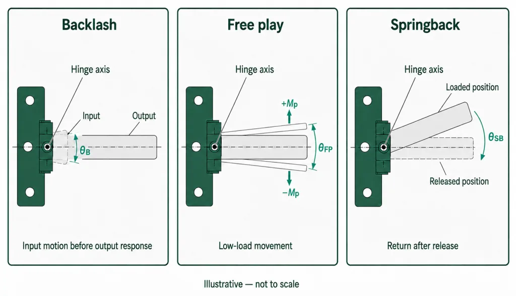
A folga de retorno, a folga livre e a recuperação elástica descrevem diferentes respostas angulares e devem ser especificadas separadamente.
Não substitua estas definições por “sem oscilação”, “retorno mínimo” ou “posicionamento preciso”. Essas expressões podem descrever uma expectativa, mas não identificam uma medida.
A dobradiça não é todo o sistema de posicionamento
Um valor de catálogo descreve normalmente uma dobradiça na peça de fixação do fornecedor. O utilizador interage com o conjunto completo, pelo que um revisão de engenharia de aplicações deve incluir a estrutura circundante. Entre esses dois pontos encontram-se os elementos de fixação de produção, os suportes, as paredes moldadas, os painéis, as pegas, os dispositivos acoplados, os cabos e, por vezes, uma articulação adicional. Cada interface pode aumentar a folga ou permitir um movimento elástico.
Isto cria um conflito de engenharia comum. Uma dobradiça cumpre os requisitos de binário e de movimento perdido do fornecedor. No equipamento, o ecrã continua a voltar visivelmente à posição inicial após ser solto. A medição de ângulo duplo revela então que as folhas da dobradiça se movem muito pouco uma em relação à outra, enquanto o suporte de montagem fino roda em relação ao chassis. A especificação nominal da dobradiça estava correta. O conjunto não era suficientemente rígido para satisfazer os requisitos de posicionamento.
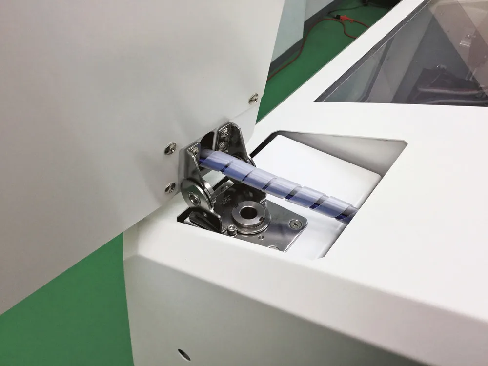
Um conjunto de dobradiças real instalado, que mostra o suporte, os elementos de fixação, a estrutura do painel e o percurso do cabo, que contribuem para a resposta de posicionamento final.
O contrário também pode acontecer. Um suporte rígido pode revelar uma folga de inversão interna que um protótipo flexível oculta temporariamente. Assim que o suporte é reforçado, o movimento restante da dobradiça torna-se mais visível. Os testes aos componentes e às montagens são, portanto, complementares, não intercambiáveis.
Mantenha a magnitude do binário separada do erro de posicionamento. O momento gravitacional ainda tem de ser suportado. Se esse valor ainda não tiver sido determinado, utilize o cálculo do binário necessário para a dobradiça. Uma dobradiça pode ter binário suficiente e demasiada folga, ou um posicionamento demasiado apertado e binário de retenção insuficiente.
O responsável pela aceitação deve decidir se o projeto diz respeito à dobradiça solta, ao subconjunto da dobradiça montada ou ao produto acabado. Um limite do componente serve de base para a inspeção do fornecedor. Um limite do conjunto protege o funcionamento final. Se for especificado apenas um, indique qual.
Escolha o ponto de referência antes do instrumento
Uma leitura angular só faz sentido entre dois pontos de referência. A expressão “medir o ângulo do painel” não especifica se o técnico está a medir a partir da bancada de trabalho, da base do suporte, da caixa, da folha da dobradiça ou do chassis. Um suporte flexível pode deslocar cada um desses pontos de referência de forma diferente.
No caso de um conjunto acabado, a superfície estável do chassis ou um ponto de referência controlado do dispositivo de fixação constitui, normalmente, a referência fixa. O alvo de saída deve estar na parte rígida do painel móvel, numa localização definida, afastada de uma aresta localmente flexível. Para um ensaio apenas com dobradiças, coloque alvos independentes nas duas folhas ou nos elementos de entrada e saída. Registe o eixo da dobradiça, uma vez que a translação do painel fora do eixo pode ser confundida com rotação.
Um inclinómetro digital pode ser adequado para uma montagem simples com referência à gravidade. Pode ser necessário um codificador rotativo, um rastreador ótico, um alvo de visão ou um par de sensores angulares quando o dispositivo de fixação se move, a faixa esperada é estreita ou os ângulos de entrada e saída têm de ser captados simultaneamente. A resolução do instrumento, por si só, não é garantia de um ensaio válido. A repetibilidade do dispositivo de fixação, o posicionamento do alvo, a zeragem, a influência do operador e o tempo de aquisição de dados também devem ser considerados na análise do sistema de medição.
θFP = |θ(+Mp) − θ(−Mp)|
θSB(t) = |θ|carregado − θdivulgado(t)|
s = r × θ
Ângulo de folga θFP é a diferença entre as posições de saída sob o momento positivo e negativo especificado da sonda Mp. Recuperação elástica θSB(t) é a diferença entre a posição de carga e a posição de libertação no momento de leitura especificado t. Movimento linear s é igual à distância em relação ao eixo da dobradiça r multiplicado pelo ângulo θ em radianos.
O deslocamento linear na borda do painel pode facilitar a visualização de um requisito, mas deve incluir o raio de medição. O mesmo erro angular produz um deslocamento maior na borda num painel de maiores dimensões. Não compare limites em milímetros medidos em raios diferentes sem os converter para uma base angular comum.
O desenho deve identificar o ponto de referência fixo, o alvo móvel, o eixo da dobradiça, o raio de medição, caso seja indicado um deslocamento linear, e a direção positiva de abertura. Estes detalhes encaixam-se naturalmente no ficha técnica e desenho da dobradiça; não devem ficar apenas numa conversa por e-mail.
Distinguir o movimento das dobradiças da flexão estrutural
Um sensor no painel indica o movimento total. Esse é o resultado correto para a aceitação funcional, mas não identifica a origem do problema. Quando o conjunto não atingir o seu limite, acrescente pontos de medição em vez de substituir peças aleatoriamente.
| Par de medição | O que está incluído | O que consegue isolar | Utilização típica |
|---|---|---|---|
| Ligar o elemento de entrada da articulação ao elemento de saída da articulação | Dobradiça interna e interfaces de encaixe imediato | Folga intrínseca, folga livre e deflexão elástica da articulação | Caracterização de fornecedores e inspeção de entrada |
| Referência do chassis em relação à folha fixa da dobradiça | Suporte de fixação lateral, elementos de fixação e parede do invólucro | Deslizamento da montagem ou rotação estrutural do lado fixo | Trabalho de análise das causas profundas na montagem |
| Deslocamento da aba da dobradiça para o painel rígido de destino | Junta do lado móvel, suporte e fixação do painel | Movimento da ligação do lado da saída | Trabalho de análise das causas profundas na montagem |
| Dados do chassis em relação ao alvo do painel funcional | A pilha completa instalada | Erro total de posicionamento detetado pelo produto | Verificação do projeto e aceitação final |
As marcas de testemunho nas juntas dos elementos de fixação ajudam a detetar deslizamentos. Um indicador de quadrante colocado na borda de um suporte pode revelar um deslocamento linear que um sensor angular não consegue detetar. Imagens de vídeo ou registos sincronizados dos sensores podem mostrar se o movimento tem origem na dobradiça, na estrutura de montagem ou no painel. A instrumentação adicional destina-se principalmente ao diagnóstico; uma verificação correlacionada durante a produção pode, muitas vezes, ser mais simples.
Verifique também a pré-carga e a restrição. Duas dobradiças com eixos não colineares podem acumular energia elástica à medida que os elementos de fixação são apertados. Um feixe de cabos pode exercer um momento de retorno que varia em função do ângulo. Um trinco ou batente pode aplicar uma pré-carga ao conjunto fechado e mascarar a folga até que o painel se afaste do mesmo. Teste a faixa de funcionamento em que o utilizador posiciona efetivamente o painel, e não apenas o batente de fecho.
Uma sequência de testes de posicionamento que outro laboratório possa repetir
O ensaio deve reproduzir o estado em que o requisito é relevante. Um ecrã montado verticalmente, uma tampa horizontal e uma dobradiça montada numa bancada estão sujeitos a momentos externos diferentes. Se o produto acabado incluir um ecrã, um painel de vidro, um puxador, um cabo ou um acabamento, utilize a massa e o centro de gravidade equivalentes aos da produção para a validação da montagem.
- Identifique o espécime. Registe o número de peça, a revisão, a referência do lote ou do número de série, a quantidade de dobradiças, a revisão do suporte, os elementos de fixação, as condições de aperto, o estado do lubrificante ou do revestimento, se aplicável, e a orientação de instalação.
- Defina o conceito de condicionamento. Indique se a amostra é nova, já foi submetida a operações anteriores, foi exposta ao ambiente ou foi submetida a um ciclo prévio. Caso seja necessário um ciclo prévio, especifique o intervalo de ângulos, a velocidade, a carga e o número de operações.
- Estabilizar as condições de ensaio. Registe a temperatura e qualquer outra condição que se saiba que afete o mecanismo. Deixe que a amostra e o dispositivo de fixação atinjam o estado requerido antes de efetuar a calibração a zero.
- Indique as referências. Ajuste o ponto de referência fixo e o alvo móvel a zero sem utilizar a mão do operador para segurar o painel no lugar. Confirme se o sensor e o dispositivo de fixação não influenciam o movimento.
- Aproxime-se do alvo a partir da direção indicada. Desloque-se com um ângulo e uma velocidade previamente definidos, de modo a que cada amostra chegue com o mesmo historial de atrito. Não coloque o painel diretamente no alvo e considere isso equivalente.
- Meça o comportamento selecionado. Para a folga axial, registe a inversão da entrada e a primeira resposta da saída. Para a folga livre, aplique o momento de sonda positivo e negativo especificados sem reposicionar intencionalmente o mecanismo. Para a recuperação elástica, registe a posição sob carga, remova a entrada sem impacto e registe a posição após a libertação no tempo indicado.
- Repita na direção oposta. Os resultados de abertura e fecho podem variar devido à direção do atrito, à gravidade, à reação do cabo, à geometria ou a uma construção assimétrica.
- Guardar as leituras individuais. Registe cada valor e cada tendência antes de calcular qualquer média. Uma média pode ocultar um valor ou uma tendência que viole o limite funcional.
Se o projeto também necessitar de uma curva completa de binário-ângulo, binário de arranque, binário de funcionamento ou resultados de retenção estática, utilize o método de medição do binário da dobradiça. O teste de posicionamento pode utilizar o mesmo dispositivo de fixação, mas os seus limiares de resposta e ângulos registados servem para uma decisão de aceitação diferente.
Não utilize uma verificação manual não definida como método final. A avaliação humana é útil para detetar uma sensação indesejável. No entanto, não é adequada para reproduzir um momento de sondagem breve, a velocidade de libertação, o tempo de permanência ou o primeiro movimento detetável da saída. Transforme a observação num teste controlado antes de a utilizar para aprovar peças de produção.
A direção, a carga e o tempo de permanência devem constar no resultado
Um único valor, sem o contexto do ensaio, cria uma precisão ilusória. A mesma montagem pode apresentar diferentes valores de retorno elástico após a abertura e após o fecho. A folga pode variar quando a gravidade inclina o painel para um dos lados da folga. O resultado também pode variar com o ângulo pretendido, uma vez que o percurso do cabo, a geometria da articulação ou a alavancagem do suporte se alteram ao longo do curso.
No mínimo, registe o ângulo alvo, a direção de aproximação, a orientação, a carga aplicada, o momento de entrada ou de sondagem, a velocidade de movimento, quando relevante, o método de libertação, o tempo de leitura, o estado de condicionamento e a temperatura. No caso de produtos multieixos, bloqueie ou controle os outros eixos. Se o produto utilizar duas dobradiças, teste o par e o espaçamento pretendidos; duas peças nominalmente idênticas podem repartir a carga de forma desigual quando os seus eixos ou superfícies de montagem estão desalinhados.
As leituras imediatas e as definitivas não devem ser combinadas. Uma leitura imediata reflete o retorno elástico. Uma leitura posterior pode incluir desvio, relaxamento, resposta térmica ou movimento do dispositivo de fixação. Se ambos os fatores afetarem o utilizador, especifique dois limites distintos e dois registos temporais.
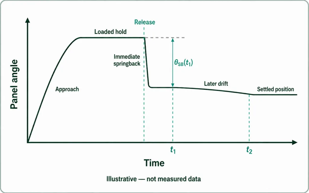
A recuperação elástica é medida no momento t1 após a libertação; o movimento posterior até ao momento t2 é registado separadamente como desvio.
Um maior número de pontos de teste não significa, automaticamente, que o resultado seja melhor. Opte pela região fechada ou quase fechada se a função for o alinhamento de um trinco, o ângulo de visão normal de um ecrã ou os ângulos de funcionamento de uma tampa. Adicione pontos finais apenas quando os batentes, a geometria ou as transições de carga representem um risco específico. O mapa de teste deve seguir a tarefa de posicionamento do produto.
Escreva o requisito em graus, não em adjetivos
O ângulo permitido deve resultar da função do produto. Um ecrã pode estar limitado pela linha de visão ou pela estabilidade ao toque. Uma tampa pode ter de permanecer dentro de um intervalo seguro ou utilizável após a libertação. A tampa de um sensor pode ter de manter o alinhamento. Uma porta pode ter de encaixar numa trava ou vedação sem que a trava puxe o mecanismo para a posição correta.
Comece pelo orçamento total para o posicionamento funcional. Atribua uma parte desse orçamento ao comportamento das dobradiças e outra parte aos suportes, articulações, deflexão dos painéis, variação de fabrico e incerteza de medição. Não atribua toda a margem do sistema às dobradiças para depois descobrir que a estrutura de suporte já não tem margem disponível.
Não existe um ângulo universal válido que possa ser aplicado a todos os projetos de articulações de torque. Um limite rígido que não possa ser medido ou mantido aumenta os custos sem proteger a funcionalidade. Um limite demasiado flexível pode permitir movimentos visíveis, instabilidade no controlo ou falhas de alinhamento. São os requisitos do equipamento que devem definir o limite; os dados relativos à capacidade do fornecedor indicam, então, se o projeto é viável.
Exemplo de estrutura de requisitos — substitua todas as variáveis pelos valores do projeto:
Com a revisão de montagem [R] instalada na orientação [O] e a suportar uma carga equivalente à de produção [L], posicione a saída no [ângulo alvo] após a aproximação a partir da direção de [abertura/fecho], percorrendo pelo menos o [ângulo de aproximação] à [faixa de velocidade].
Jogo livre sob momento de sonda alternado ±[Mp] não deve exceder [θFP] pico a pico, medido entre o ponto de referência do chassis [D] e o alvo de saída [P].
Após manter a posição de carga durante [th] e retirando a força de acionamento sem impacto, a recuperação elástica em [t1] não deve exceder [θSB1]. Variação angular adicional em [t2] não deve exceder [θD].
A folga após a inversão não deve exceder [θB] quando for detetada uma resposta de saída no limiar definido de [ângulo/momento]. Aplique o limite a cada amostra e a cada direção especificada, salvo indicação em contrário no desenho.
Esta formulação distingue entre os dados de entrada do teste, a resposta ao movimento e a aceitação. Além disso, evita que a expressão “jogo zero” se torne uma afirmação impossível de testar. Cada resultado tem um limiar e uma base de medição.
| Campo de especificações | O que indicar | Porque é importante |
|---|---|---|
| Artigo sujeito a controlo | Dobradiça solta, subconjunto montado ou produto acabado | Define quais as distâncias de segurança e estruturas que estão incluídas |
| Comportamento angular | Contrabalanço, folga, retorno elástico e/ou desvio temporizado | Impede que movimentos diferentes sejam registados sob uma única etiqueta |
| Referência e alvo | Referência fixa, ponto de saída e direção positiva designados | Permite comparar as leituras entre os equipamentos de medição e os laboratórios |
| Estado de carga | Massa, centro de gravidade, momento externo e orientação, conforme aplicável | Identifica a tensão que atua nas folgas e nas peças elásticas |
| Histórico de moções | Direção de aproximação, ângulo prévio, velocidade, método de retenção e libertação | Controla o histórico de atrito e a energia elástica armazenada |
| Condição de deteção | Momento de sondagem ou limiar de resposta | Transforma “o início do movimento” num acontecimento objetivo |
| Tempo de leitura | Tempo de permanência imediato e/ou indicado | Distingue a recuperação elástica da deriva posterior |
| Regra de aceitação | Limite por unidade e por direção, além de quaisquer requisitos estatísticos | Impede que as médias ocultem os exemplares não conformes |
Se for necessário negociar limites com vários fornecedores, certifique-se primeiro de que os termos e as condições de cada um têm o mesmo significado. O Comparação das especificações das dobradiças de binário constante explica como as definições de binário e os dados obtidos podem diferir. Para a precisão de posicionamento, adicione os campos «ponto de referência», «limiar do sensor», «direção» e «tempo» apresentados acima.
Incorporar os limites angulares na inspeção de produção
As primeiras amostras devem ser avaliadas para além de uma simples classificação de «aprovado» ou «reprovado». Representem graficamente ou apresentem em tabelas os resultados individuais por amostra, ângulo e direção. Isto permite determinar se o problema se deve a um desvio consistente, a uma assimetria direcional, a uma grande variação entre unidades, a um problema de ângulo localizado ou a uma alteração após o condicionamento. As médias, por si só, são especialmente pouco reveladoras quando o utilizador identifica a unidade com pior desempenho.
A verificação do projeto ao nível da montagem deve utilizar suportes, elementos de fixação, instruções de aperto, massa do painel, centro de gravidade, percurso dos cabos e batentes, tal como se fossem utilizados na produção. Um dispositivo de desenvolvimento maquinado pode comprovar o comportamento das dobradiças, ao mesmo tempo que oculta a conformidade da estrutura estampada ou moldada. Teste ambos quando o orçamento para o posicionamento do sistema for limitado.
A inspeção de produção pode ser reduzida a um conjunto mais restrito de pontos correlacionados. Por exemplo, um teste de inversão definido no ângulo de funcionamento mais sensível pode detetar a folga, enquanto um teste controlado de movimento e libertação capta a recuperação elástica. O teste reduzido só é válido depois de os trabalhos de engenharia demonstrarem que este prevê a totalidade dos requisitos. Não se deve partir do princípio de que a sensação tátil estática ou uma leitura de binário constituem um substituto.
O instrumento de medição deve distinguir a variação do processo da variação da medição. Recorra a um estudo do sistema de medição adequado ao equipamento e à decisão a tomar. O desgaste do dispositivo de fixação, o ponto zero do sensor, o posicionamento da amostra, a força de fixação e a técnica do operador devem ser monitorizados. Se a banda de aceitação for estreita em relação à incerteza de medição demonstrada, reveja o método, adicione uma banda de segurança à decisão ou reconsidere o requisito antes da libertação.
Registo de precisão de posicionamento
- As revisões de peças, desenhos, suportes e acessórios são rastreáveis.
- O artigo sujeito a controlo — dobradiça, subconjunto ou produto acabado — é explicitamente indicado.
- O ponto de referência, o alvo, o eixo e a direção positiva correspondem ao desenho.
- A orientação, a carga aplicada, o centro de gravidade e o estado do cabo correspondem ao produto pretendido.
- A direção de aproximação, o momento de teste, a velocidade de movimento, a retenção, a libertação e o tempo de leitura são controlados.
- Os valores individuais são registados por amostra, ângulo e direção.
- O ecrã de produção foi correlacionado com o teste de engenharia completo.
- O sistema de medição permite fundamentar a decisão de aceitação.
O que uma alegação de «backlash» ou «springback» realmente prova
Uma expressão presente numa ficha técnica, como “jogo zero” ou “recuperação elástica mínima”, constitui uma indicação útil para a conceção, mas não representa, por si só, um resultado de aceitação do projeto. Pergunte o que foi medido, qual foi o dispositivo de fixação e a orientação, o intervalo de ângulos, a direção, o limiar de deteção, o número e o estado das amostras, e se a afirmação se aplica a todas as unidades ou a uma caracterização típica.
O relatório de resultados mais completo identifica a revisão da peça testada e inclui o método, o equipamento calibrado, as leituras em bruto ou ao nível da unidade, os limites de aceitação e o tratamento dado aos resultados não conformes. Um certificado resumido pode servir de base para lotes de rotina após correlação, mas não permite reconstruir um método original não definido.
Os dados dos componentes do fornecedor também não podem certificar um suporte que o fornecedor não tenha concebido ou um painel que o fornecedor não tenha testado. Atribua as responsabilidades de forma explícita: o fornecedor das dobradiças controla o comportamento intrínseco da peça no dispositivo de fixação acordado; o fabricante do equipamento controla a geometria da instalação e o posicionamento do produto completo. A resolução conjunta de problemas recorre a ambos os conjuntos de dados.
Se nenhum modelo existente tiver margem de posicionamento suficiente, a conversa seguinte deverá partir dos requisitos medidos do sistema, em vez de um pedido de “mais binário”. Analise as opções disponíveis tendo em conta o binário necessário, o envelope, a interface de montagem e os limites de folga da articulação, folga livre e retorno elástico do projeto.
Apresentar um requisito de posicionamento mensurável
Para uma discussão útil sobre o modelo, forneça o desenho do painel ou do ecrã, o eixo da dobradiça e a interface de montagem, a massa móvel e o centro de gravidade, o intervalo de ângulos úteis, o binário necessário, a folga/jogo livre/recuperação elástica permitida, a direção de aproximação, o ponto de referência de medição, a orientação da carga e os resultados de amostras disponíveis. Essas informações permitem comparar as geometrias e especificações candidatas sem considerar “estável” ou “preciso” como valores universais.
Questões sobre a precisão do posicionamento das dobradiças de torque
Uma dobradiça de elevado binário pode, mesmo assim, apresentar um erro de posicionamento demasiado grande?
Sim. A magnitude do binário e a precisão de posicionamento são características distintas. Uma dobradiça pode resistir ao momento exigido pelo painel e, ainda assim, apresentar uma folga de inversão, um movimento de montagem ou uma recuperação elástica que excedam a tolerância do sistema.
“Jogo zero” significa que não há absolutamente nenhum movimento angular?
Não sem um limiar de teste definido. Cada medição tem uma resolução finita e um método para detetar a resposta de saída. Solicite informações sobre o equipamento de teste, a entrada aplicada, o limiar de resposta e a resolução dos resultados subjacentes à alegação.
A recuperação elástica da dobradiça de torque é sempre corrigida através do ajuste?
Não. O efeito de retorno elástico pode ser causado pela torção elástica na dobradiça, mas também pode ser provocado pelas lâminas, suportes, fixadores, paredes do invólucro, pelo painel ou pela reação do cabo. Meça ambos os lados da interface em causa antes de alterar o binário.
A tolerância de posicionamento deve ser especificada em graus ou milímetros?
Normalmente, os graus são mais claros no que diz respeito ao comportamento rotacional. Também é possível utilizar um limite em milímetros num ponto funcional, mas o desenho deve indicar a sua distância em relação ao eixo da dobradiça. Sem esse raio, os resultados lineares de diferentes conjuntos não são comparáveis.
A tolerância relativa à deformação de reação e à deformação de retorno deve aplicar-se a cada unidade ou à média do lote?
Aplique o máximo funcional a cada unidade, salvo indicação em contrário na especificação aprovada. As médias por lote e as estatísticas de capacidade podem apoiar o controlo do processo, mas não devem ocultar uma dobradiça ou orientação específica que exceda o limite de posicionamento.