-
+86 13720060320
-
lanna@haitangs.com

Hoe scharnieren voor milieutestkamers met afgedichte deuren te kiezen
De deur van een milieutestkamer kan bij kamertemperatuur goed afsluiten, maar toch zijn afdichting verliezen zodra de kamer zijn bedrijfstoestand heeft bereikt.
Het scharnier is misschien wel sterk genoeg. De grendel sluit misschien nog steeds. Het probleem kan elders liggen: een geïsoleerde deur verandert van vorm onder invloed van een temperatuurgradiënt, het kozijn en de scharnierbeugel zetten verschillend uit, de pakking wordt stijver of juist soepeler, en de grendel trekt het paneel naar één kant van het afdichtingsvlak.
De keuze van scharnieren voor klimaatproefkamers met afgedichte deuren is daarom niet louter een kwestie van draagvermogen. De scharnieras, de bevestigingsconstructie, de vorm van de afdichting, de werking van de vergrendeling, de gebruikte materialen, het condensatiepad en de volledige cyclus van de kamer moeten ervoor zorgen dat de deur telkens weer in dezelfde gecontroleerde gesloten stand terugkeert.
Deze pagina richt zich uitsluitend op die ene taak. Er wordt geen uitspraak gedaan over het koelsysteem, de temperatuuruniformiteit in de kamer, de prestaties van de regelaar, het plaatsen van proefstukken of een algemene grenswaarde voor de bedrijfstemperatuur van een scharnier.
De deur ging dicht, maar het zegel veranderde
Een kamerdeur wordt doorgaans eerst bij omgevingstemperatuur gecontroleerd. De technicus sluit de grendel, controleert of het randcontact goed aansluit en gaat na of de deur zonder te schuren opengaat. Die controle is noodzakelijk. Het gaat hierbij niet om de bedrijfstoestand.
Tijdens een cyclus van warmte, kou of vochtigheid bewegen de binnenbekleding, de buitenbekleding, het kozijn, de versteviging, de scharnierbeugel, het raam, de isolatie en de pakking niet noodzakelijkerwijs synchroon mee. Een kleine hoekverandering ter hoogte van de scharnierlijn kan de druk op één hoek verminderen, terwijl de drukvergrendeling de tegenoverliggende rand strak tegen het kozijn blijft trekken.
De vergrendeling zat strakker, terwijl de onderste afdichting aan de scharnierzijde open ging
Een kamerdeur sloot bij kamertemperatuur normaal. Na herhaalde koudecycli moest de gebruiker meer kracht uitoefenen om de deur te vergrendelen. De toegenomen kracht leek de afdichting te verbeteren, maar een controlestrook in de onderste hoek aan de scharnierzijde vertoonde minder samendrukking dan voorheen. De pakking aan de vergrendelingszijde werd samengedrukt terwijl de deur lichtjes rond een gewijzigde scharnieras draaide.
De aanpassing betrof niet alleen een stevigere vergrendeling. Bij de evaluatie moest ook rekening worden gehouden met de scharnierbeugel, de stijfheid van de geïsoleerde deur, de aspositie, het afdichtingsvlak en de spleet bij gesloten deur bij verschillende temperaturen.
Dit is een illustratief technisch scenario, geen verslag van een klantproject of bewering op basis van producttests.
Selectiegrens: Keur het scharnier pas goed als de complete deurconstructie tijdens de volledige werkcyclus van de kamer haar voorgeschreven uitlijning en pakkingcompressie behoudt. Een pascontrole bij kamertemperatuur is onvoldoende om die beslissing te onderbouwen.
De geïsoleerde deur is de echte belasting
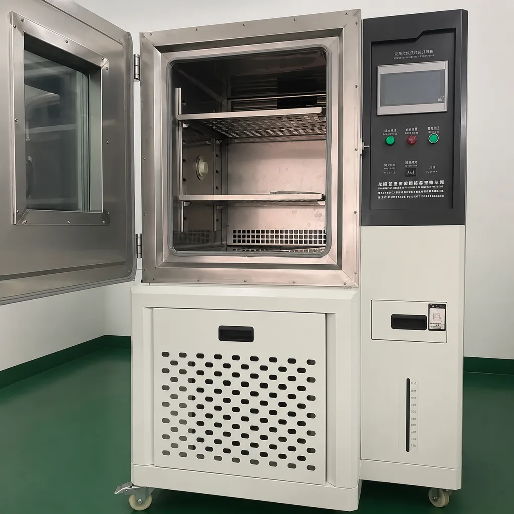
De belasting op de kamerdeur bestaat uit meer dan alleen het buitenpaneel. Isolatie, binnenbekleding, kijkvenster, verwarmd glas, bedrading, handgreep, vergrendelingsstangen, drukmechanismen, beschermkappen, verstevigingen en gemonteerde instrumenten kunnen ervoor zorgen dat het zwaartepunt van de scharnierlijn afwijkt.
Gebruik de massa en het zwaartepunt zoals bedoeld voor de productie. Een onbewerkt fabricagemonster kan lichter, dunner en beter uitgebalanceerd zijn dan de definitieve deur. Dat verschil beïnvloedt het moment op het scharnier, de doorbuiging van de bevestigingsrand en de kracht die nodig is om de grendel aan de tegenoverliggende kant in te trekken.
Het referentiemoment kan worden omschreven als het gewicht van de deur dat inwerkt op de horizontale afstand ten opzichte van de scharnieras. De werkelijke scharnierreacties zijn ook afhankelijk van de afstand tussen de scharnieren, de stijfheid van de deur, de stijfheid van het kozijn, de montagetoleranties en het aantal en de positie van de sluitingen.
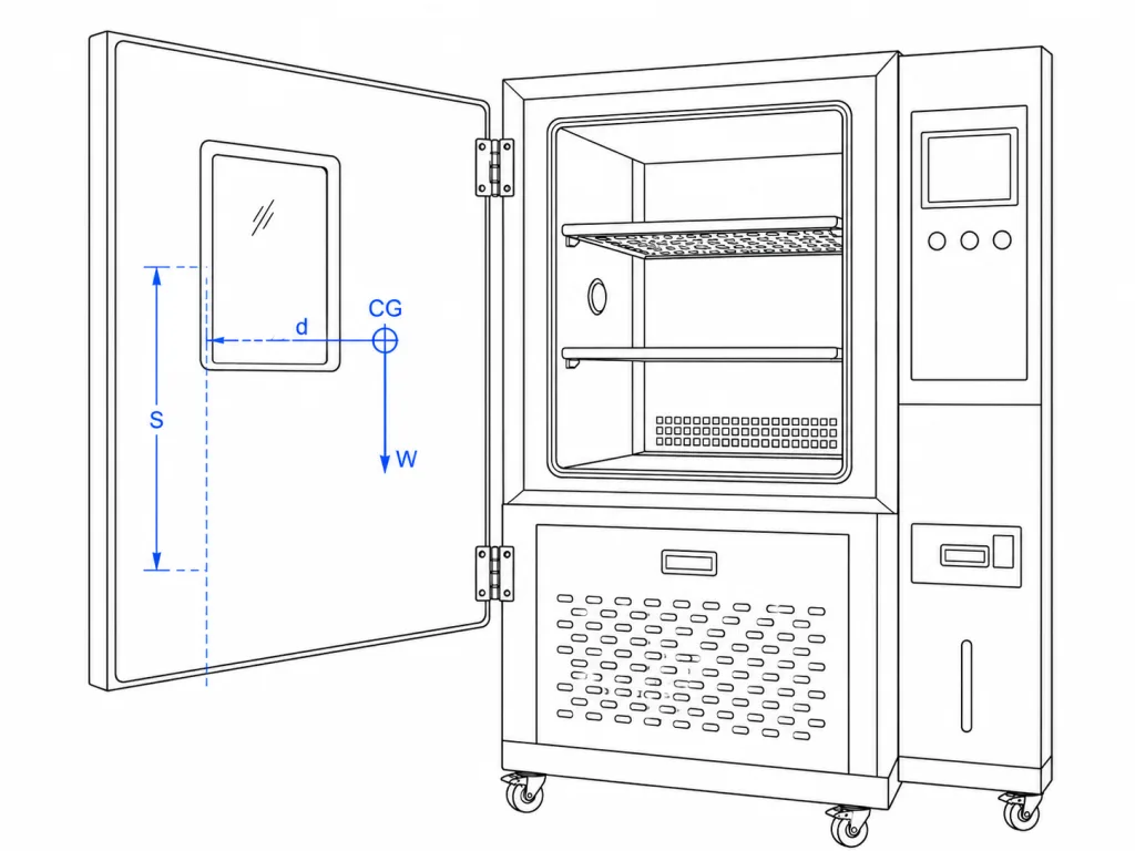
Gebruik voor de gedetailleerde berekening van statische momenten, scharnierafstanden en wapening de geleider voor scharnier van zware behuizingsdeur. Deze pagina bouwt voort op die uitgangssituatie en gaat verder met de compressietest op afdichtingen en thermische cycli.
Scharnieras ten opzichte van het afdichtingsvlak
De scharnieras bepaalt hoe de deur de afdichting nadert en weer verlaat. Als de as te dicht bij het afdichtingsvlak ligt, kan de rand aan de scharnierzijde tijdens het openen over de afdichting schuren. Als de afstand te groot is, kan de deur weliswaar soepel wegzwaaien, maar wordt er een groter moment uitgeoefend op de scharnierbeugel en de bevestigingsconstructie.
Geef de deur in doorsnede weer, niet alleen in vooraanzicht. Geef de hartlijn van de pen, de binnen- en buitenbekleding, de isolatie, de frame-uitsteek, de pakking (bolvormig of profielvormig), de samendrukrichting, de sluitlijn en eventuele thermische onderbrekingen tussen de warme en koude zijden weer.
De gesloten stand vereist een herhaalbaar mechanisch referentiepunt. De vergrendeling moet de beoogde druk uitoefenen nadat de deur naar dat referentiepunt is teruggekeerd; het mag niet de functie zijn die een afwijkende scharnieras corrigeert.
Door thermische cycli beweegt het gewricht
Bij een kamerdeur kan er een groot temperatuurverschil optreden tussen de binnenbekleding en de constructie aan de kamerzijde. De omvang en richting daarvan zijn afhankelijk van het type kamer, de bedrijfsvolgorde, de isolatie, de luchtstroom, het ontwerp van het venster en de verblijfsomstandigheden. Het scharnier bevindt zich dwars over die bewegende constructie.
Door ongelijke uitzetting kunnen de vlakheid van de bladeren, de hoek van de beugels, de voorspanning van de bevestigingsmiddelen, de toestand van de vulplaatjes en de coaxiale uitlijning tussen meerdere scharnieren veranderen. De deur kan nog steeds openen en sluiten, maar het ene scharnier kan de randbelasting gaan dragen, terwijl het andere scharnier de vervormde constructie volgt.
| Verandering in de thermische cyclus | Wat het kan vervoeren | Bewijs op deuropname | Technisch antwoord |
|---|---|---|---|
| De binnenste en buitenste lagen zetten zich verschillend uit | Vlakheid van de deur en hoek van de rand aan de scharnierzijde | Spelingverandering, afdrukpatroon van de pakking, wrijving bij het openen | Meet de volledige deur onder vastgestelde kamercondities |
| Voor het frame en de beugel worden verschillende materialen of profielen gebruikt | Scharnieras ten opzichte van het afdichtingsvlak | Verandering in de sluitkracht, verlies aan compressie aan de scharnierzijde | Stapel van referentiemateriaal, stijfheid van de beugel en asreferentiepunt |
| Bevestigingsmiddelen en montagevlakken worden herhaaldelijk gebruikt | Voorspanning van de verbinding, positie van de sleuf en plaatsing van de vulplaatjes | Sporen van verschuiving, slijtage, plaatselijke beschadiging van de coating | Stel de vergrendelingsmethode vast en controleer deze na het doorlopen van de cyclus |
| De stijfheid van de pakking verandert naargelang de toestand | Sluitkracht en lokale compressie | Verschillende vergrendelingskracht bij hoge temperaturen, kou of vochtige omstandigheden | Het gedrag van de pakking loskoppelen van de uitlijning van het scharnier |
| Er ontstaat condens of vorst in de buurt van de voeg | Vrije ruimte, afwatering en wrijving bij het draaien | Tijdelijke vastzitting, resten, corrosie bij het onderste scharnier | Zorg voor afwatering en voer een op de toestand afgestemde inspectie uit |
Beschouw een temperatuurwaarde op een materiaalgegevensblad niet als een goedkeuring voor gebruik in een testkamer. De reactie van het samenstel hangt af van de combinatie van geometrie, raakvlakken, de bedrijfsvolgorde en de blootstellingstijd.
Het naar binnen trekken van de grendel kan een scharnierfout verbergen
Compressiesluitingen zijn ontworpen om de deur naar het kozijn toe te trekken en zo druk op de pakking uit te oefenen. Deze werking kan ook doorzakken van de deur, verschuiving van de scharnieras of vervorming van het kozijn verbergen.
Meet de deur voordat de grendel volledig is ingetrokken. Noteer de spleten aan de scharnierzijde en aan de grendelzijde, de positie van de deur ten opzichte van het referentiepunt van de afdichting en de slag van de grendel die nodig is om de afdichting samen te drukken. Noteer vervolgens de uiteindelijke gesloten toestand.
Wanneer de grendel de deur zijwaarts moet trekken, een hoek moet optillen of een grote hoekafwijking moet compenseren, brengen het scharnier en het kozijn het deurpaneel niet langer terug naar de ontgrendelde stand. Meer grendelkracht kan de schade aan de pakking op die plek vergroten, zonder dat de druk elders wordt hersteld.
Nuttige diagnose: Vergelijk de onbelaste gesloten stand met de volledig vergrendelde stand. Een grote verandering wijst erop dat de vergrendeling de geometrie van de deur corrigeert en niet alleen de pakking samendrukt.
Kaartcompressie langs de rand
Een afdichting mag niet worden beoordeeld op basis van één punt ter hoogte van de handgreep. Deuren van klimaatkamers zijn vaak voorzien van meerdere sluitingen, een dik geïsoleerd paneel en een pakking waarvan het gedrag verandert onder invloed van temperatuur en vochtigheid.
Maak een herhaalbare compressiekaart van de bovenste scharnierhoek, de onderste scharnierhoek, de bovenste vergrendelingshoek, de onderste vergrendelingshoek en elke lange, niet-ondersteunde rand. Gebruik de door de kamerfabrikant vastgestelde methode, zoals een gecontroleerde spleetmeting, drukgevoelig meetmateriaal, meting van de doorbuiging van de pakking of een andere voor het project goedgekeurde techniek.
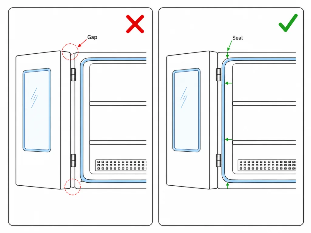
De methode en de acceptatiewaarden zijn projectspecifiek. Het doel van de kaart is om aan te geven of de scharnierlijn en het vergrendelingssysteem de belasting gelijkmatig verdelen — niet om één universeel percentage voor de pakkingcompressie vast te stellen.
| Waargenomen patroon | Waarschijnlijk een vraag over mechanica | Volgende controle |
|---|---|---|
| Geringe compressie bij beide hoeken aan de scharnierzijde | Ligt de scharnieras te ver van het afdichtingsvlak of staat deze er schuin van af? | Controleer de aspositie, de hoek van de beugel en het gesloten referentiepunt |
| Lage compressie alleen bij de onderste scharnierhoek | Is de deur doorgezakt of is de onderste bevestigingsconstructie verschoven? | Meet de deuropening, de scharnierpositie en de bevestigingsnaad |
| Hoge druk aan de vergrendelingszijde bij lage druk aan de scharnierzijde | Wordt de deur bij het inschuiven van de grendel rond de scharnierlijn gedraaid? | Vergelijk de posities van de deur in onbelaste toestand en in vergrendelde toestand |
| Veranderingen in de compressie na warmte- en koudecycli | Hebben temperatuurgradiënten invloed op de vlakheid van de deur of de geometrie van het kozijn? | Leg de toestand vast, breng de verblijfsduur in kaart en maak een volledige omtrekkaart |
| Een plaatselijk verpletterd gebied | Wordt de belasting geconcentreerd door een grendel, een verschuiving van het scharnier of een onderbreking in het kozijn? | Controleer de lokale stijfheid en de afstand tussen de vergrendeling en het scharnier |
Pivot-materialen bij hoge en lage temperaturen
Het materiaal van het scharnierhuis vormt slechts een onderdeel van het scharnier. De pen, de bus of het lager, de drukring, de klem, de bevestigingsmiddelen, het smeermiddel, de coating en de montagebeugel kunnen elk op een andere manier reageren op temperatuur en vocht.
Lage temperaturen kunnen de weerstand van smeermiddelen vergroten of de stijfheid van polymeren beïnvloeden. Hoge temperaturen kunnen de viscositeit van smeermiddelen verlagen, de migratie versnellen of de kruip van polymeren beïnvloeden. Herhaalde temperatuurschommelingen kunnen condensatie in spleten doen binnendringen en bevestigingsverbindingen door uitzetting en krimp onder druk zetten.
Vraag om materiaal- en smeermiddelinformatie op componentniveau voor de exacte scharniervariant. Accepteer “roestvrijstalen scharnier” niet als volledige specificatie van de omgevingsomstandigheden. De pen en de klem kunnen van een ander materiaal zijn gemaakt, en het smeermiddel of polymeer kan de functionele grens bepalen nog voordat de vleugels dat doen.
- Verbinding tussen pen en lager: bepaal of er sprake is van glij- of rolcontact, de speling, de oppervlakteafwerking en de axiale ondersteuning.
- Smeermiddel: het type, de locatie, de migratieroute, de onderhoudsregel en de relevante temperatuurgegevens vaststellen.
- Polymeeronderdelen: bepaal de exacte grenswaarden voor materiaal, belasting, retentie, blootstelling aan vocht en temperatuur.
- Bevestigingsmiddelen en klemmen: controleer of de vergrendeling, het hergebruik en de controleerbaarheid na herhaaldelijk openen en sluiten nog steeds in orde zijn.
- Oppervlakteafwerking: Controleer de randen, gaten, lasnaden en contactpunten – niet alleen het zichtbare oppervlak van het blad.
Condens, vorst en het onderste scharnier
Vocht verdeelt zich niet gelijkmatig rondom de deur. In het onderste scharnier kunnen condens, schoonmaakresten, gesmolten ijs en vuil van de drempel van de kamer zich ophopen. Een verzonken uitsparing of een overlappende deurvleugel kan nat blijven nadat het omliggende paneel is opgedroogd.
Geef het laagste afvoerpunt in de gemonteerde stand aan. Het ontwerp mag er niet toe leiden dat water in de scharnier, de bevestigingsgaten, de isolatienaad of de verborgen holte van de beugel terechtkomt. De verbinding moet bovendien voldoende toegankelijk zijn voor inspectie en reiniging.
Tijdelijke vorst kan de openingsspeling en de weerstand van het scharnier beïnvloeden. Een technicus kan extra kracht uitoefenen en het scharnier, de grendel, de handgreep of het kozijn belasten voordat het ijs is losgekomen. De fabrikant van de kamer moet de veilige openingsvoorwaarden en de bedieningsprocedure vastleggen; het scharnier mag niet worden gebruikt om een onveilige openingsvolgorde te compenseren.
Wanneer corrosietesten deel uitmaken van de eisen voor scharnieren, moeten de toestand van het proefstuk, de blootstelling, de beoordelingslocaties, de toegestane verandering en de functionele acceptatiecriteria worden vastgelegd. Een zoutneveltest bootst de volledige bedrijfscyclus van de kamer niet na.
Vast, verborgen of afneembaar?
Voor veel afgedichte kamerdeuren is een vaste, stevig bevestigde constructie de eerste ontwerprichting, omdat een herhaalbare uitlijning doorgaans belangrijker is dan het gereedschaploos verwijderen. De uiteindelijke keuze hangt nog steeds af van de onderhoudstaak, het totale gewicht van de deur, de geometrie van de afdichting en de uitgevoerde validatie. Een verborgen scharnier kan de buitenste beslagonderdelen beschermen en het buitenoppervlak schoonhouden, maar de interne beugel, de afwatering en de afstelpunten moeten nog steeds toegankelijk zijn.
Vast scharnier voor opbouwmontage
Door deze constructie kunnen de pen, bevestigingsmiddelen, lasnaden en afvoerweg gemakkelijker worden geïnspecteerd. Bovendien worden de bevestigingsonderdelen hierdoor over de thermische en vochtgrens heen geplaatst, waardoor de materiaallaag en de doorvoeren in de constructie moeten worden gecontroleerd.
Verborgen scharnier
Een verborgen verbinding zorgt ervoor dat beslag niet aan de buitenzijde zichtbaar is en kan bijdragen aan een ononderbroken oppervlak van de behuizing. Het nadeel is een verborgen holte waarin vocht kan blijven zitten, die de verstelmogelijkheden kan beperken of waardoor thermische bewegingen moeilijker te controleren zijn.
Opklapbare of afneembare deur
Een verwijderbare kamerdeur mag alleen worden gebruikt wanneer volledige verwijdering een daadwerkelijke onderhoudsvereiste is. Het ontwerp moet de druk op de pakking opheffen, axiale speling bieden, het zware geïsoleerde paneel op zijn plaats houden, verwarmingselementen of sensoren loskoppelen en de deur weer op hetzelfde afdichtingsniveau terugbrengen.
Raadpleeg de Richtlijnen voor de speling bij het losklappen van het scharnier en de richting van de pen.
Openingsstop en onderhoudsruimte
Het scharnier mag niet als onbedoelde eindstop voor de kamerdeur fungeren. Een zware, geïsoleerde deur kan een krachtige stoot veroorzaken wanneer deze het einde van de slag bereikt, vooral als een bediener de deur snel duwt of als de vloer niet waterpas is.
Gebruik een structurele aanslag, bevestiging, bevestigingsmiddel of onafhankelijke steun met een krachtdoorvoer naar een geschikte deur- en kozijnconstructie. Laat de openingsgrens niet worden bepaald door een pakking, verwarmingskabel, sensorkabel, verbindingsband of sluitmechanisme.
De bruikbare werkruimte wordt bepaald door de onderhoudstaken. Controleer of technici proefstukken kunnen plaatsen, rekken kunnen verwijderen, bij de instrumenten kunnen komen, de pakking kunnen reinigen en het onderste scharnier kunnen inspecteren zonder dat de deur de werkruimte blokkeert.
Bij inloopkamers en grote vloerstaande kamers kan het ook nodig zijn om de bediening van de deuren op oneffen vloeren of tijdens de installatie te regelen. Deze omstandigheden horen thuis in de volledige montagebeoordeling, niet in een vermelding van de nominale openingshoek van de scharnieren.
Montage door een geïsoleerde constructie heen
Bij een kamerdeur wordt vaak gebruikgemaakt van dunne platen rondom een dikke, geïsoleerde kern. De belasting op het scharnier mag niet uitsluitend op de buitenste plaat rusten. Er is een versterkte verbinding nodig met een kozijn, een binnenplaat, een gevormde terugloop, een gelaste beugel of een ander constructie-element.
Doorvoerbouten kunnen thermische bruggen of geleidingswegen in het isolatiesysteem veroorzaken. Gelaste beugels kunnen het afdichtingsvlak vervormen voordat de deur wordt gemonteerd. Sleufgaten vergemakkelijken de afstelling, maar vereisen een gecontroleerde vergrendeling en markeringen, omdat herhaalde thermische cycli de verbinding kunnen verschuiven.
De tekening moet de daadwerkelijke dragende constructie weergeven, en niet alleen de dikte van de zichtbare buitenlaag. Ook moet de hartlijn van de scharnierpen na het lassen, het schuimen, de afwerking, het aanbrengen van de pakking en de definitieve afstelling van de vergrendeling worden gecontroleerd.
Gebruik voor steunplaten, plaatselijke versteviging, het voorbereiden van gaten en bevestigingsdetails voor dunwandige constructies de montagehandleiding voor scharnieren van dun plaatmetaal.
Volgens de normen van de Kamer mag het scharnier niet worden gekozen
IEC 60068-3-6 beschrijft methoden voor het controleren van de prestaties van temperatuur- en temperatuur-/vochtigheidskamers. Bij het project dient de toegewezen editie en de toepasselijke kameromstandigheden te worden gebruikt. De norm schrijft geen specifieke scharnieren, sluitingen, pakkingen of deurverstevigingen voor.
Een kamer kan onder één geteste conditie aan de gespecificeerde temperatuur- of vochtigheidsprestaties voldoen, terwijl het deurbeslag nog steeds afzonderlijk mechanisch moet worden getest op het gebied van openen, sluiten, thermische cycli, condensatie en onderhoud.
Vermeld niet dat een scharnier “voldoet aan IEC 60068”, tenzij deze bewering wordt onderbouwd door een exacte eis, een testmonster, een testopstelling, een testresultaat en een goedkeuringsverklaring. In het project moeten de deurspecifieke grenswaarden worden vastgelegd voor uitlijningsverandering, samendrukpatroon, bedieningskracht, slijtage, corrosie en bruikbaarheid na de testcyclus.
Standaardgrens: Prestatienormen voor kamers kunnen bepalen hoe de kamer wordt gekarakteriseerd. Ze bieden geen universele temperatuurclassificatie voor scharnieren en bewijzen evenmin dat een bepaald deurbeslag zijn afdichting behoudt.
Scharnieren van een milieutestkamer bij thermische cycli
Een los scharniermonster kan het moment van de geïsoleerde deur, de vervorming van het kozijn, de stijfheid van de pakking, het inschuiven van de grendel, het condensatiepad of de interactie tussen meerdere scharnieren niet nabootsen. Controleer de complete, voor productie bestemde deur of een gedocumenteerde opspanning die deze interacties nabootst.
Omgevingsreferentiewaarde
Noteer het scharniermodel en de revisie, de positie van de pennen, de bevestigingsmiddelen, de montagesleuven, de spleten bij gesloten deur, het referentiepunt van de afdichting, de slag van de grendel, de openingskracht, de compressiekaart van de pakking, de afvoerroute en het kijkvenster of het op de deur gemonteerde beslag.
Vastgestelde kamervolgorde
Houd rekening met de bedrijfsvolgorde van het project, de temperatuur- en vochtigheidsomstandigheden, de verblijftijd, de herstelfase en het aantal cycli. De ontwerper van de kamer moet vastleggen wanneer de deur veilig mag worden geopend en welke metingen worden verricht bij het bereiken van de gewenste toestand, tijdens de herstelfase of na terugkeer naar omgevingstemperatuur.
Volg de mechanische verandering
Controleer de beweging van de gleuf, de markeringen van de bevestigingsmiddelen, de verschuiving van de scharnieras, de weerstand bij het draaien, het verschuiven van smeermiddel, vorst of condens, beschadigingen aan de coating, de vlakheid van de deur, de kracht die nodig is om de grendel te bedienen en de druk langs de randen. Leg verbanden tussen de waarnemingen. In het openingsscenario bleek een grotere kracht die nodig was om de grendel te bedienen niet te leiden tot een betere afdichting; het verhulde een gewijzigde geometrie aan de scharnierzijde.
Herhalingsdienst en herstel
Open de deur vanuit de juiste onderhoudshoek, bedien de stop- of vergrendelingsmechanisme, inspecteer de pakking en het onderste scharnier, en verwijder of monteer de deur alleen opnieuw als dit deel uitmaakt van het normale onderhoud. Controleer daarna of het paneel terugkeert naar hetzelfde referentiepunt zonder dat de grendel het zijdelings wegduwt.
Stel vóór het testen acceptatiecriteria op. “De kamer heeft het instelpunt bereikt” en “de deur is nog steeds gesloten” zijn onvoldoende acceptatiecriteria voor scharnieren.
Bewijsmateriaal vrijgeven voor de exacte herziening
Het vrijgavepakket moet één scharnierversie koppelen aan één constructie van de kamerdeur en één validatievoorwaarde bij installatie. Een productfamiliebeschrijving zoals “roestvrijstalen scharnier voor zwaar gebruik” is geen gecontroleerde definitie.
Scharnierconstructie
- Onderdeelnummer en revisienummer van de gecontroleerde tekening
- Pen, lager of bus, druklager en bevestiging
- Materialen, afwerkingen en smeermiddel
- Openingshoek en aanslaginterface
Geometrie van de deur en de afdichting
- Totale massa en zwaartepunt
- Afstand tussen scharnieren en as ten opzichte van de referentiepunten van de kamer
- Afdichtingsvlak, profiel van de pakking en posities van de vergrendelingen
- Geïsoleerde bekledingen, versteviging en bevestigingsconstructie
Bedrijfsomstandigheden
- Kamervolgorde en voorwaarde voor veilig openen
- Door het project toegewezen blootstelling aan temperatuur en luchtvochtigheid
- Condensatie, vorst en blootstelling aan reinigingsmiddelen
- Instelhoek, aanslag en procedure voor verwijderbare deur
Monster- en wijzigingsbeheer
- Identiteit van het productiemodel
- Compressiekaart vóór en na de cyclus
- Goedgekeurde afstel- en vergrendelingsinstellingen
- Wijzigingen waarvoor een technische beoordeling of hervalidatie vereist is
Voor algemene uitleg over tekeningaanduidingen, toleranties, materialen, afwerkingen en de interpretatie van prestatie-opmerkingen, raadpleeg de Specificatieblad voor scharnieren en handleiding voor technische tekeningen.
Stuur de tekening van het kamerdeel en de afdichting
Geef de volledige massa van de geïsoleerde deur, de afstand tussen de scharnieren, het bevestigingsprofiel, de positie van de scharnieras, het profiel en het afdichtingsvlak van de pakking, de posities van de sluitingen, de bedieningsvolgorde, de blootstelling aan condensatie, de openingshoek en het bewijs van installatie zoals vereist door het project. HSP kan de scharnieropbouw en de tekeninggegevens beoordelen voordat de monsters worden vergeleken.
Vragen over de scharnieren van de milieutestkamer
Welke scharnieren worden gebruikt voor de deuren van klimaatproefkamers?
Milieutestkamers kunnen worden uitgerust met vaste, op het oppervlak gemonteerde, verborgen, op lagers ondersteunde, vastgelaste of verwijderbare scharnierconstructies. De keuze voor het juiste type hangt af van het moment op de geïsoleerde deur, de positie van de scharnieras, het vlak van de pakking, de werking van de vergrendeling, de bedieningsvolgorde, de blootstelling aan condensatie en de vereiste toegankelijkheid voor onderhoud.
Waarom kan een kamerdeur na thermische cycli gaan lekken?
Temperatuurgradiënten kunnen de vlakheid van de deur, de geometrie van het kozijn, de positie van de scharnieras, de voorspanning van de bevestigingsmiddelen, het gedrag van de pakking en het inspringen van de grendel beïnvloeden. De kamer kan nog steeds sluiten, terwijl de drukverdeling langs de omtrek ongelijkmatig wordt.
Is roestvrij staal geschikt voor een scharnier van een testkamer?
Nee. Ook de pen, het lager of de bus, de drukring, de klem, de bevestigingsmiddelen, het smeermiddel, de coating, de beugel en de aangrenzende materialen moeten worden gecontroleerd. Functionele beperkingen kunnen het gevolg zijn van het draaipunt of het bevestigingssysteem, en niet zozeer van de scharniervleugels.
Moet de grendel worden gebruikt om het doorhangen van de kamerdeur te verhelpen?
Nee. Het scharnier en de bevestigingsconstructie moeten ervoor zorgen dat de deur terugkeert naar de vastgestelde gesloten referentiepositie. De grendel moet de beoogde druk op de pakking uitoefenen en mag een verkeerd uitgelijnd paneel niet optillen of in de juiste positie draaien.
Kan de deur van een klimaatkamer worden voorzien van afneembare scharnieren?
Ja, wanneer het volledig verwijderen van de deur een daadwerkelijke servicevereiste is. Het ontwerp moet voorzien in drukontlasting, axiale speling, veilige hantering van de geïsoleerde deur, het loskoppelen van kabels of verwarmingselementen, betrouwbare vergrendeling en een herhaalbare terugkeer naar het afdichtingsreferentiepunt.
Wat moet er worden vastgelegd tijdens de validatie van de scharnieren van de kamerdeur?
Noteer de exacte aanpassingen aan de scharnieren en de deur, het totale gewicht van de deur, de geometrie van de as en de afdichting, de slag van de vergrendeling, de compressiekaart langs de omtrek, de volgorde van de kamers, de montagetoestand, waarnemingen met betrekking tot condensaat of ijsvorming, de uitlijning na de cyclus, de bedieningskracht en de testbeperkingen.
Technische beperking: Dit artikel vormt een kader voor de selectie en validatie van scharnieren voor testkamers. Het certificeert geen scharnier of voltooide testkamer voor een specifiek temperatuurbereik, vochtigheidsbereik, drukomstandigheden, veiligheidsfunctie, prestatienorm voor testkamers of testprocedure van de klant. De exacte grenswaarden en acceptatiecriteria blijven projectspecifiek.