-
+86 13720060320
-
lanna@haitangs.com

Hoe lees je een specificatieblad en een technische tekening van Hinge?
Een specificatieblad voor een scharnier kan er volledig uitzien omdat het een productafbeelding, verschillende afmetingen, een materiaalnaam en een belasting- of koppelwaarde bevat. Een technische tekening kan er zelfs nog gezaghebbender uitzien omdat deze aanzichten, toleranties, symbolen en een revisieblok bevat. Geen van beide documenten is echter bruikbaar, tenzij de lezer precies kan zien wat vastligt, wat louter beschrijvend is, wat nog onbevestigd is en welke prestatieclaims afhankelijk zijn van afzonderlijke testomstandigheden.
In deze handleiding wordt uitgelegd hoe ingenieurs, inkopers bij OEM’s, kwaliteitsteams en projectmanagers een specificatieblad voor scharnieren en een tekening van de leverancier moeten bestuderen voordat ze een monster of een productieorder goedkeuren. De handleiding begint na de scharnierfamilie is al geselecteerd. Als er voor het project nog een keuze moet worden gemaakt tussen scharnieren met koppel, verzonken scharnieren, afneembare scharnieren, aanlasbare scharnieren, veerscharnieren of standaardscharnieren, begin dan met onze gids over Hoe kies je een industrieel scharnier?.
Kort antwoord: Lees een scharniertekening in deze volgorde: documentidentiteit en revisie, eenheden en projectie, productconfiguratie, totale omhulling, patroon van bevestigingsgaten, individuele en algemene toleranties, materiaal en afwerking, functionele eisen, testvoorwaarden voor belasting of koppel, en goedkeuringsstatus. Keur een scharnier nooit goed op basis van één aantrekkelijke afmeting of één enkele waarde voor de “maximale belasting”. De tekening, het specificatieblad, de testresultaten en het goedgekeurde monster moeten betrekking hebben op hetzelfde onderdeel en dezelfde revisie.
Technische specificaties, tekening, testrapport en monster: vier verschillende soorten bewijsmateriaal
Projecten op het gebied van industriële scharnieren mislukken vaak omdat vier verschillende documenten worden behandeld alsof ze hetzelfde aantonen. Dat is echter niet het geval.
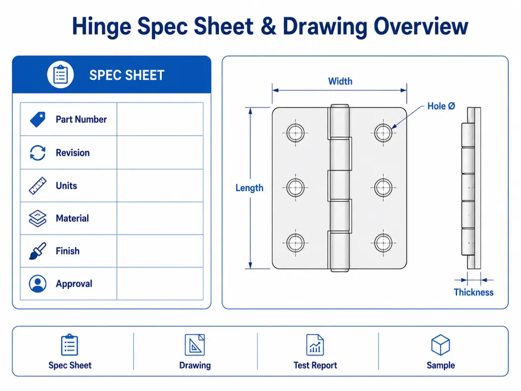
| Document of bewijsstuk | Wat het zou moeten omschrijven | Wat het op zichzelf niet bewijst |
|---|---|---|
| Productspecificatieblad | Productfamilie, belangrijkste afmetingen, materiaal, afwerking, functie, nominale prestaties, beschikbare opties | Elke afmeting van het productieproces, alle toleranties of naleving van orderspecifieke eisen |
| Technische tekening | Gecontroleerde geometrie, gatenpatroon, afmetingen, toleranties, opmerkingen over het materiaal, oriëntatie, revisie | Werkelijke levensduur, corrosiebestendigheid, gebruiksgemak of geschiktheid voor geïnstalleerde systemen, tenzij er testvereisten zijn opgenomen |
| Testrapport | Testmethode, identificatie van het monster, opspanning, omstandigheden, metingen en resultaten | Dat elke toekomstige productiebatch overeenkomt met het geteste monster |
| Goedgekeurd voorbeeld | Fysieke pasvorm, beweging, uiterlijk van het oppervlak, montagegedrag en gevoel bij het vasthouden | De kwaliteit van het verwerkte materiaal, alle afmetingen, de levensduur of een herhaalbare productiecontrole zonder ondersteunende documentatie |
De vier zouden elkaar moeten steunen bij inspectie en testcontrole. Een monster dat goed aanvoelt maar niet overeenkomt met de goedgekeurde tekening, vormt geen betrouwbare productiereferentie. Een tekening met een aanhaalmomentwaarde maar zonder testmethode voor het aanhaalmoment laat ruimte voor verschillende interpretaties. Een materiaalcertificaat voor SUS 304 bevestigt niet dat de afmetingen of afwerking overeenkomen met de bestelling.
1. Begin met documentbeheer, niet met de afmetingen
Controleer, voordat u de scharniergeometrie doorneemt, of het document zelf kan worden geïdentificeerd en gecontroleerd. Veel kostbare fouten ontstaan doordat het juiste ontwerp in de verkeerde revisie wordt goedgekeurd.
| Veld ‘Titelblok’ | Wat je moet controleren | Waarom het belangrijk is |
|---|---|---|
| Artikelnummer | Exact onderdeelnummer van de leverancier en de klant | Soortgelijke scharniermodellen kunnen alleen verschillen in koppel, draairichting, penrichting of afwerking |
| Tekeningsnummer | Identificatiecode van het gecontroleerde document | Het tekeningnummer kan afwijken van het commerciële modelnummer |
| Herziening | Revisiebrief of -nummer en beschrijving van de wijziging | Een gewijzigd gatenpatroon of materiaal komt mogelijk niet tot uiting in de bestandsnaam |
| Datum | Datum van uitgave en herziening | Helpt vaststellen of de offerte het meest recente document gebruikt |
| Status | Voorlopig, voor offerte, voor monster, goedgekeurd of vrijgegeven | Een offerte-tekening hoeft niet automatisch een productietekening te worden |
| Eenheden | Millimeter, inch, graden, N·m, N·cm, lbf·in of andere eenheden | Een aanname op unitniveau kan een aanzienlijke afwijking of prestatiefout veroorzaken |
| Schaal | Tekenschaal en opmerking “niet schalen” | De afmetingen moeten gebaseerd zijn op de opgegeven waarden, niet op metingen die zijn uitgevoerd op basis van een PDF-afbeelding |
| Projectiemethode | Symbool voor projectie vanuit de eerste hoek of vanuit de derde hoek | Verandert de manier waarop de lezer de relatie tussen weergaven interpreteert |
| Toepasselijke tekeningsnorm | Bedrijfsnorm, ASME, ISO GPS of projectnorm | Bepaalt hoe symbolen, toleranties en standaardinstellingen worden geïnterpreteerd |
Als de leverancier de tekening aanpast, vraag dan om een overzicht van de wijzigingen. “Bijgevoegde bijgewerkte tekening” is niet voldoende. De beoordelaar moet weten of de wijziging gevolgen heeft voor de pasvorm, de werking, het materiaal, de gereedschappen, de keuring of de uitwisselbaarheid.
2. Bepaal de exacte scharnierconfiguratie
Een tekening kan weliswaar de juiste buitenvorm weergeven, maar de functionele opbouw onduidelijk laten. Controleer het producttype en alle opties die van invloed zijn op de installatie of de beweging.
- Standaard vrijschommelend, torsie-, veer-, vergrendelings-, verborgen, aanlas-, afneembaar of draaischarnier
- Linkshandige, rechtshandige, omkeerbare of niet-handgebonden configuratie
- Met de klok mee, tegen de klok in, in één richting of in twee richtingen: weerstand tegen torsie
- Toewijzing van deurvleugel en kozijnvleugel
- Bevestigingsrichting en verwijderingsrichting voor afneembare scharnieren
- Startpositie, vergrendelingshoeken of volledige omwenteling
- Met of zonder bussen, ringen, afdichtingen, afdekkappen of bevestigingsmateriaal
- Standaardmodel, aangepast standaardmodel of volledig op maat gemaakt onderdeel
Ga er niet zomaar vanuit dat twee scharnieren met dezelfde totale afmetingen onderling uitwisselbaar zijn. Een verborgen aanslag, een andere bevestigingswijze van de pen, een omgekeerde draairichting of een andere koppelrichting kunnen ervoor zorgen dat het onderdeel niet geschikt is, zelfs als alle bevestigingsgaten op één lijn liggen.
3. Bekijk eerst de afbeeldingen voordat je de cijfers leest
In technische tekeningen wordt gebruikgemaakt van meerdere aanzichten, omdat één aanzicht niet alle kenmerken kan weergeven. Probeer, voordat u de maatstralen volgt, vast te stellen wat elk aanzicht weergeeft.
| Weergavetype | Wat er meestal op een scharnier te zien is |
|---|---|
| Vooraanzicht of bovenaanzicht | Omtrek van het blad, patroon van de gaten, totale lengte en breedte |
| Zijaanzicht | Bladdikte, knokkeldiameter, verspringingen, buigingen, inbouwhoogte |
| Achteraanzicht | Positie van de pen, uitlijning van de loop, vorm van de beugel, open of gesloten profiel |
| Doorsnede | Pen, bus, ringen, frictiestapel, veer of verborgen interne onderdelen |
| Gedetailleerd overzicht | Kleine details zoals bevestigingspunten, verzinkingen, sleuven, groeven of bevestigingsschroeven |
| Opengewerkte tekening | Relatie tussen de volgorde van de componenten en de assemblage |
| Weergave vanuit een alternatieve positie | Open hoek, gesloten hoek, eindpositie of bewegingsbereik |
Controleer of de weergegeven positie open, gesloten, ontlast of gemonteerd is. Een verborgen scharnier kan in geopende toestand heel andere afmetingen hebben. Op een tekening van een torsiescharnier kan het midden van de as wel zijn aangegeven, maar niet de benodigde speling voor het bewegende paneel. Op een tekening van een lift-off-scharnier kan de gemonteerde hoogte wel zijn aangegeven, maar niet de benodigde ontkoppelingsslag.
4. Controleer de totale afmetingen en de beschikbare ruimte voor de installatie
De totale lengte en breedte zijn nog maar het begin. Het scharnier moet zowel in statische als in bewegende toestand goed passen.
- Totale lengte en breedte van het blad
- Gesloten dikte of inbouwhoogte
- Diameter van de knokkel, de cilinder of de behuizing
- Uitsteeklengte van spijkerkop, schroefkop en sluitring
- Verspringing tussen de scharnieras en het bevestigingsvlak
- Vereiste uitsparing of opening voor verborgen scharnieren
- De envelop door het volledige openingsbereik bewegen
- Toegang tot gereedschap voor het vastdraaien, afstellen, vastzetten of verwijderen van schroeven
- Speling tussen kabels, slangen, pakkingen en aangrenzende onderdelen
Gebruik de montagetekening om te controleren of de scharnierruimte overeenkomt met de werkelijke afmetingen van de deur en het kozijn. Een tekening van de leverancier kan de afmetingen van het scharnier aantonen, maar kan niet aantonen of er voldoende ruimte is in uw kast, machinebehuizing, display of toegangsluik, tenzij beide tekeningen in een Beoordeling van de interface voor het tekenen en monteren.
5. Het patroon van de bevestigingsgaten aflezen vanaf een referentiepunt
Bij gatenpatronen kunnen ogenschijnlijk kleine verschillen in de tekening leiden tot montagefouten. Controleer niet alleen de diameter van de gaten. Lees de volledige montage-specificatie door.
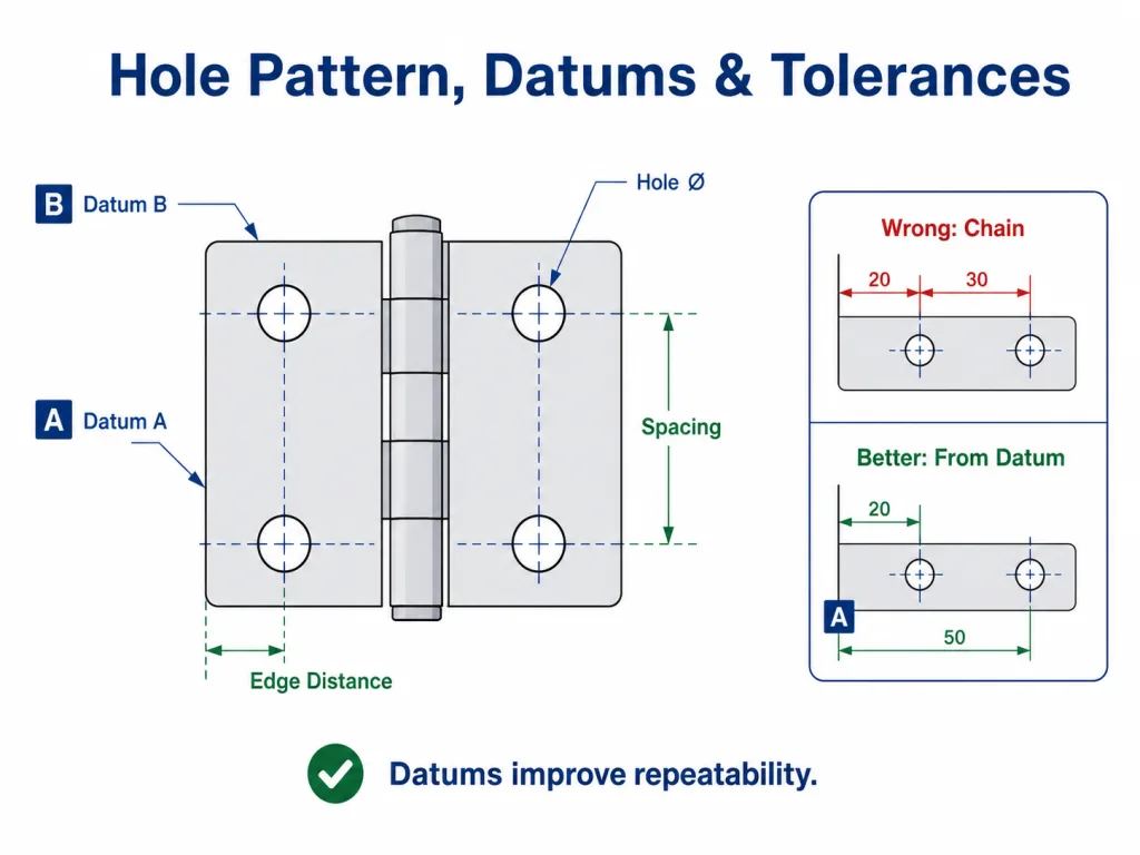
| Functie 'Gatpatroon' | Vragen die je moet stellen |
|---|---|
| Diameter van het gat | Speling, schroefdraad, uitgeboord of perspassing? Welk bevestigingsmiddel is bedoeld? |
| Afstand van hart tot hart | Wordt het patroon bepaald vanuit een gemeenschappelijk referentiepunt of wordt het van gat tot gat doorgetrokken? |
| Randafstand | Is er voldoende materiaal tussen het gat en de bladrand om vervorming te voorkomen? |
| Afmetingen en richting van de sleuf | Kan de sleuf worden aangepast in de richting die voor de montage daadwerkelijk nodig is? |
| Verzinkboor | Inclusief hoek, hoofddiameter, diepte en het beoogde type schroefkop? |
| Tegenboring | Zijn de diameter en de diepte voldoende voor de kop van het bevestigingsmiddel en het gereedschap? |
| Discussie | Schroefdraadnorm, nominale maat, spoed, klasse en minimale ingrijping? |
| Patroonpositie | Hoe is het volledige patroon gepositioneerd ten opzichte van de scharnieras en de bevestigingsrand? |
Een gatenpatroon dat wordt bepaald door aaneengeschakelde afmetingen kan afwijkingen vertonen. Voor een kritische uitlijning moet uit de tekening duidelijk blijken welke oppervlakken, randen of assen als referentiepunten dienen. Dit is met name van belang wanneer meerdere scharnieren één as moeten delen of wanneer de grendel en de pakking afhankelijk zijn van een herhaalbare deurpositie.
6. Maak een onderscheid tussen nominale afmetingen en toleranties
Een nominale maat geeft de beoogde afmeting aan. De tolerantie bepaalt de toegestane afwijking. Een maat zonder zichtbare plus-/minwaarde kan toch onderworpen zijn aan een algemene tolerantieaanduiding in het titelblok.
| Tolerantie-indeling | Voorbeeld | Betekenis |
|---|---|---|
| Symmetrisch | 20,0 ± 0,2 mm | Het toegestane bereik ligt tussen 19,8 en 20,2 mm |
| Eenzijdig | 20,0 +0,2 / -0,0 mm | De afmeting mag groter zijn dan de nominale waarde, maar niet kleiner. |
| Maximale afmetingen | 19,8–20,2 mm | De minimum- en maximumwaarden worden direct vermeld |
| Angular | 90° ± 1° | Regelt de buig-, blad-, stop- of beugelhoek |
| Algemene tolerantie | ISO 2768-klasse of bedrijfsopmerking | Geldt wanneer er geen individuele tolerantie is aangegeven, binnen de aangegeven toepassingsgebied |
| Referentieafmeting | (20,0) of REF | Meestal louter informatief en geen op zichzelf staande toelatingseis |
Lees de algemene opmerking over toleranties zorgvuldig door. ISO 2768 wordt vaak gebruikt om de tolerantieaanduidingen voor afmetingen zonder afzonderlijke toleranties te vereenvoudigen, maar het betreffende onderdeel, de klasse, de reikwijdte van het proces en de projecteisen moeten nog steeds duidelijk zijn. Een afzonderlijk vermelde tolerantie heeft doorgaans voorrang op de algemene opmerking. Op de actuele tekening van de leverancier moet de exacte norm of interne tolerantietabel worden vermeld die wordt gebruikt. De officiële beschrijving van ISO 2768 door de ISO legt uit dat de norm bedoeld is om de aanduidingen op tekeningen te vereenvoudigen door algemene tolerantieklassen vast te stellen.
Strakker is niet automatisch beter. Een onnodig krappe tolerantie kan de kosten voor verspaning, stansen, gereedschap en inspectie verhogen zonder dat de werking van het scharnier daardoor verbetert. De beoordelaar moet zich afvragen welke afmetingen daadwerkelijk bepalend zijn voor de passing, uitlijning, beweging, afdichting of uitwisselbaarheid.
7. Inzicht krijgen in de GD&T-specificaties die het belangrijkst zijn voor scharnieren
Geometrische maatvoering en tolerantie bepalen niet alleen de afmetingen van een onderdeel, maar ook de vorm, oriëntatie en positie. ASME Y14.5 is een veelgebruikte norm voor maatvoering en tolerantie, terwijl ISO 1101 de ISO GPS-symbooltaal en de interpretatieregels voor geometrische specificaties vastlegt. Op de tekening moet worden aangegeven welk systeem van toepassing is, omdat tekeningen die op elkaar lijken, verschillende standaardregels kunnen volgen. ASME beschrijft Y14.5 als de toonaangevende richtlijn voor de GD&T-ontwerptaal, en ISO 1101 definieert de symbooltaal voor geometrische specificaties.
| Besturing | Waarom dit op een scharnierpunt van belang kan zijn |
|---|---|
| Datum | Stelt het referentiekader vast voor gatenpatronen, scharnieras en bevestigingsvlakken |
| Functie | Bepaalt de positie van gaten of een gatenpatroon ten opzichte van referentiepunten |
| Vlakheid | Zorgt ervoor dat de bladen zonder te wiebelen of te verdraaien op hun plaats blijven zitten |
| Parallelisme | Kan tegenoverliggende bevestigingsvlakken, bladen of gerelateerde assen aansturen |
| Loodrechtheid | Kan beïnvloeden: beugels, bevestigingsvlakken of de stand van de pennen |
| Profiel | Kan gevormde, gegoten of complexe blad- en beugelvormen aansturen |
| Slag | Kan van belang zijn voor roterende assen, draaibare onderdelen of cilindrische elementen |
Interpreteer een GD&T-kader niet uitsluitend op basis van het symbool. Lees de tolerantiewaarde, de referentiepunten, eventuele materiaal- en toestandmodificatoren en het kenmerk waaraan het kader is gekoppeld. Bij een patroon met meerdere gaten is de positie ten opzichte van stabiele referentiepunten doorgaans nuttiger dan het afzonderlijk controleren van elke hart-op-hartafmeting.
8. Materiaal op componentniveau lezen
“Roestvrijstalen scharnier” is geen volledige materiaalspecificatie. Een scharnier kan uit verschillende materialen bestaan, zoals de scharniervleugels, de pen, de bus, de frictieringen, de veer, de bevestigingsmiddelen en de afdekking.
| Component | Belangrijke informatie ter bevestiging |
|---|---|
| Bladeren of stam | Exacte legering of kwaliteit, dikte, basis voor gieten of vervormen |
| Pen of as | Kwaliteit, hardheid, oppervlaktebehandeling, bevestigingsmethode |
| Bus of lager | Polymeer, brons, staal of ander materiaal; smeerbehoefte |
| Wrijvingselementen | Materiaalgroep, geschiktheid voor bepaalde temperaturen, gedrags bij samendrukking |
| Lente | Materiaal, warmtebehandeling, richting en voorspanning werden gecontroleerd |
| Bevestigingsmiddelen | Materiaal, kwaliteit, coating, schroefdraad en of het bij de levering is inbegrepen |
Wanneer in de tekening SUS 304 of SUS 316 wordt vermeld, moet u nagaan voor welke onderdelen deze kwaliteit wordt gebruikt. Ga er niet zomaar vanuit dat als een vleugel van 316 is, de pen en de schroeven ook van 316 zijn. Zie voor een meer gedetailleerde vergelijking van de omgevingsfactoren onze gids over SUS 304 versus SUS 316 scharnieren.
Bij kritieke bestellingen moet de materiaalkwaliteit worden gestaafd door het overeengekomen certificaat of inspectierapport. De tekening bepaalt de eis; het materiaaldocument dient als onderbouwing voor de productiebatch.
9. Beschouw de afwerking als een vastgestelde eis
De oppervlakteafwerking is van invloed op het uiterlijk, de corrosiebestendigheid, de wrijving, de pasvorm, de elektrische continuïteit en de montage. Aanduidingen als “zwart”, “verzinkt” of “gepassiveerd” zijn mogelijk te vaag voor een goedkeuringstekening.
- Afwerkingswijze en bijbehorende processpecificatie
- De dikte van de coating of het metaallaagje wanneer dit functioneel van belang is
- Kleur-, glans- en textuurreferentie voor zichtbare onderdelen
- Vereisten inzake passivering of nabehandeling
- Gebieden rondom schroefdraad, aardingspunten, lagers of wrijvingsoppervlakken afplakken
- Toegestane afwijkingen wat betreft krassen, vlekken, kleurverschillen of zichtbaar basismetaal
- Of de afmetingen gelden vóór of na het aanbrengen van de coating
Afzettingen kunnen de speling in de gaten verkleinen, de pasvorm van de verzinkkop veranderen, invloed hebben op de uitsparingen voor verborgen scharnieren of ervoor zorgen dat het scharnier vastloopt. Uit de tekening moet duidelijk blijken welke kritische afmetingen van toepassing zijn op het afgewerkte onderdeel.
10. Lees de functionele specificatie voor het scharniertype
Aan de hand van de geometrie kun je zien of het scharnier past. Aan de hand van de functionele specificatie kun je zien of het de vereiste taak kan uitvoeren. Verschillende scharnierfamilies vereisen verschillende prestatiegebieden.
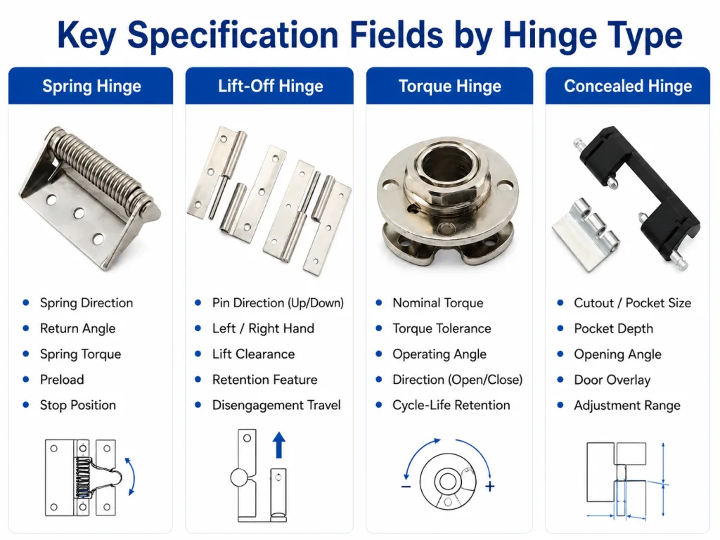
| Scharniertype | Functionele gebieden om op te letten |
|---|---|
| Standaardscharnier | Openingsbereik, penbevestiging, lager of bus, vrije beweging, toegestane speling |
| Koppel- of wrijvingsscharnier | Nominaal koppel, tolerantie, draairichting, aanloopkoppel, werkhoek, temperatuur, behoud van levensduur |
| Verstelbaar draaimoment scharnier | Instelbereik, instelmethode, vergrendelingsmethode, meetomstandigheden |
| Veerscharnier | Sluit- of openingsrichting, veerkracht, voorspanning, werkhoek, terugkeerpositie |
| Scharnier met vergrendeling | Vergrendelingshoeken, vergrendelingskracht, ontgrendelingskracht, hoektolerantie |
| Afneembaar scharnier | Richting van de pen, draairichting, ontkoppelingsweg, anti-liftbeveiliging, deur- en kozijnvleugel |
| Verborgen scharnier | Uitsparing, zakdiepte, openingshoek, interferentie-envelop, instelbereik |
| Lasbaar scharnier | Laslocatie, materiaalcompatibiliteit, penbescherming, uitlijning na het lassen |
| Draaischarnier | Draaibereik, axiale en radiale belasting, koppel, slingering, diameter voor kabelgeleiding |
Een koppelwaarde zonder richting en meetomstandigheden is onvolledig. Een veerbeschrijving zonder voorbelastingsrichting is onvolledig. Een afheftekening zonder de verwijderingsvector is onvolledig. Functionele velden moeten beschrijven hoe de exacte configuratie zich gedraagt, en niet alleen hoe de productfamilie heet.
11. Let niet alleen op het draagvermogen, maar houd ook rekening met de testomstandigheden
“Maximale belasting: 50 kg” lijkt misschien doorslaggevend, maar vormt geen basis voor technische goedkeuring, tenzij de testopstelling bekend is. Het gewicht van de deur alleen geeft geen informatie over het moment, de inbouwstijfheid of de belastingsverdeling.
| Vraag over het draagvermogen | Waarom dit het resultaat beïnvloedt |
|---|---|
| Hoeveel scharnieren zijn er getest? | Eén, twee en drie scharnieren verdelen de belasting niet noodzakelijkerwijs gelijkmatig |
| Wat was de afstand tussen de scharnieren? | De afstand beïnvloedt de stabiliteit van de deur en de gewichtsverdeling |
| Wat was de laadrichting? | Radiale, axiale, trek-, afschuif- en momentbelastingen oefenen druk uit op verschillende onderdelen |
| Hoe breed was de deur, of hoe lang was de hefboomarm? | Een bredere deur zorgt voor een groter moment rond de scharnieras |
| Welk bevestigingsmateriaal is er gebruikt? | Stijve staalplaten en dun plaatstaal gedragen zich niet op dezelfde manier |
| Welke bevestigingsmiddelen zijn er gebruikt? | De afmetingen, de vergrendeling en de ondergrond van de bevestigingsmiddelen kunnen de wijze van falen beïnvloeden |
| Statische of cyclische test? | Een statische duurzaamheidstest is geen bewijs voor de duurzaamheid bij herhaald gebruik |
| Welk acceptatiecriterium werd toegepast? | Geen breuk is hetzelfde als geen blijvende vervorming of geen doorhangen van de deur |
| Is er rekening gehouden met een veiligheidsfactor? | De in de catalogus vermelde “maximale” en de aanbevolen werklast hoeven niet hetzelfde te zijn |
Als de leverancier geen volledige testomstandigheden kan bieden, moet de waarde worden beschouwd als voorlopige catalogusinformatie. Voor de definitieve goedkeuring moeten de daadwerkelijke deur, de afstand tussen de scharnieren, de bevestigingsconstructie en de gebruiksomgeving worden gebruikt, of een representatieve, gevalideerde testopstelling.
12. Bekijk de gegevens over het koppel en de levensduur in onderlinge samenhang
Bij koppelscharnieren is het aanvankelijke koppel slechts één van de specificatiepunten. Het document dat meer informatie biedt, beschrijft hoe het koppel wordt gemeten en in hoeverre dit tijdens het gebruik kan veranderen.
- Nominaal koppel per scharnier
- Toegestane koppeltolerantie
- Richting van het openen en sluiten
- Losbreekkoppel versus draaikoppel
- Meethoek en snelheid
- Temperatuur en voorbereiding vóór de meting
- Aantal cycli
- Eis inzake behoud van koppel na herhaalde belasting
- Toegestane geluid, vastlopen, speling of afwijking
Vergelijk de koppelwaarden van twee leveranciers niet met elkaar, tenzij de eenheid, richting, hoek, snelheid, temperatuur en testmethode vergelijkbaar zijn. Een hogere cataloguswaarde betekent niet automatisch dat het beter is; een te hoog koppel kan de inspanning van de gebruiker vergroten en de bevestigingsconstructie beschadigen.
13. Controleer de milieueisen en acceptatiecriteria
In een tekening kunnen het materiaal en de afwerking worden gespecificeerd, terwijl in het specificatieblad de blootstelling aan temperatuur, vochtigheid, zoutnevel, reinigingsmiddelen, UV-straling, stof of afspoelingen wordt vermeld. Ga na of het hier gaat om ontwerpdoelstellingen, testomstandigheden of algemene marketingclaims.
Wat zoutneveltests betreft, volstaat de testnorm op zich niet. ASTM B117 beschrijft de apparatuur, de procedure en de omstandigheden voor een gecontroleerde zoutnevelomgeving, maar definieert op zichzelf niet de productspecifieke blootstellingsduur of hoe de resultaten moeten worden beoordeeld. De eis moet ook het aantal uren, de toestand van het proefstuk, al dan niet beschermde of ingekerfde oppervlakken (indien relevant), de toegestane mate van corrosie en of het scharnier na de test nog moet kunnen bewegen of loskomen, vermelden. ASTM waarschuwt ook dat op zichzelf staande zoutneveltestresultaten geen betrouwbare voorspelling geven van de prestaties in een natuurlijke omgeving. Zie de officiële toepassingsgebieden en beperkingen van ASTM-norm B117.
| Milieusector | Wat er in een te beoordelen specificatie moet staan |
|---|---|
| Bedrijfstemperatuur | Minimum, maximum en of de functie bij die temperaturen moet worden gemeten |
| Corrosietest | Methode, duur, voorbereiding, acceptatiecriteria en werking na de test |
| Reinigingschemicaliën | De genoemde chemische stoffen, concentratie, temperatuur en blootstellingsmethode, voor zover bekend |
| Afspoelbeurt | Druk, temperatuur, richting, duur en vereiste voor volledige montage |
| Trillingen of schokken | Testprofiel, scharnieroriëntatie, toestand van de deur en functionele goedkeuring |
| Blootstelling in de buitenlucht | UV-straling, regen, condensatie, omstandigheden aan de kust of met chloride, en aannames inzake onderhoud |
14. Controleer de greep, de richting en de openingshoek
Termen als ‘links’ en ‘rechts’ kunnen misleidend zijn als niet duidelijk is vanuit welke kant er wordt gekeken. De tekening moet de oriëntatie zowel visueel als verbaal duidelijk maken.
- Vastgestelde kijkzijde voor links- en rechtsaanduiding
- Richting waarin de deur opengaat
- Deurvleugel en kozijnvleugel
- Pinrichting of asrichting
- Koppelrichting met de klok mee en tegen de klok in
- Gesloten positie en nulhoekreferentie
- Maximale openingshoek
- Mechanische aanslag of toegestane overloop
- Vergrendelingsposities en hoektolerantie
Gebruik pijlen en gelabelde weergaven in plaats van uitsluitend op de productnaam te vertrouwen. Controleer bij gespiegelde dubbele deuren of de twee onderdelen echte spiegelbeelden zijn, omkeerbare onderdelen of hetzelfde onderdeel dat in verschillende richtingen is gemonteerd.
15. Lees de aanwijzingen voor bevestigingsmiddelen en montage
Een scharniertekening kan correct zijn, terwijl de montagewijze niet is vastgelegd. Controleer of de leverancier de bevestigingsmaterialen voorschrijft of slechts aanbeveelt.
- Bevestigingsmiddelen inbegrepen of apart geleverd
- Afmetingen van schroeven of bouten, spoed, kwaliteit, materiaal en afwerking
- Vereiste sluitring, vergrendelingsmechanisme, schroefdraadborgmiddel, moer, klinkmoer of steunplaat
- Minimale schroefdraadoverbrenging
- Aanbevolen of voorgeschreven aandraaimoment
- Dikte en stijfheid van het montagepaneel
- Eisen inzake vlakheid en uitlijning van de montageoppervlakken
- Afmetingen, plaats, volgorde en beschermde zones van lasverbindingen voor opgelaste scharnieren
- Afstelprocedure en laatste vergrendelingsstap
Beschouw de diameter van een bevestigingsgat niet als een volledige specificatie van de bevestigingsmiddelen. De verbinding kan eerder bezwijken dan het scharnier als de schroefvergrendeling, de plaatdikte, de randafstand of de versteviging onvoldoende zijn.
16. Afzonderlijke offerte van de leverancier, voorbeeldtekening en goedkeuring van de productie
Niet elke tekening die bij een offerte is gevoegd, hoeft voor productie te worden goedgekeurd. Maak gebruik van duidelijke documentfasen.
| Beoordelingsfase | Doel | Wat kan worden goedgekeurd | Wat open moet blijven |
|---|---|---|---|
| Catalogus of voorlopige beoordeling | Controleer de basisgegevens over het gezin, de grootte en de mogelijke pasvorm | Of het model het waard is om nader te worden onderzocht | Eindtolerantie, prestaties, materiaalbewijs, productiestatus |
| Offertetekening | De aangehaalde configuratie en uitzonderingen definiëren | Commerciële vergelijkingsbasis | Controle van de pasvorm van het monster en definitieve functionele validatie |
| Voorbeeldtekening | De afmetingen en configuratie van het besturingsprototype controleren | Wat moet er worden gebouwd voor het testen van monsters? | Productiestart pas nadat het monster is goedgekeurd |
| Goedgekeurde productietekening | Leg het overeengekomen deel en de inspectiegrondslag vast | Afmetingen, materialen, afwerking, functionele opmerkingen, herziening | Alleen gedocumenteerde afwijkingen of latere herzieningen |
Als de klant de tekening wijzigt, moeten de commerciële en technische gevolgen worden beoordeeld via het proces voor maatwerkontwikkeling, in plaats van via een informele e-mail te worden afgehandeld. Onze gids voor de Ontwikkelingsproces voor scharnieren op maat beschrijft het traject van de beoordeling van de tekening tot en met het proefexemplaar en de productie.
17. Veelvoorkomende onvolledige of dubbelzinnige specificaties voor scharnieren
| Formulering in het document | Wat ontbreekt er? | Waarom het riskant is |
|---|---|---|
| “Roestvrijstalen scharnier” | Kwaliteitsklassen van onderdelen, afwerking, materialen van pennen en bevestigingsmiddelen | Verschillende leveranciers kunnen verschillende uitvoeringen aanbieden |
| “Draagvermogen: 50 kg” | Aantal scharnieren, afstand tussen scharnieren, hefboomarm, montage, keuring en oplevering | De waarde kan niet met zekerheid worden toegepast op de echte deur |
| “Koppel: 3 N·m” | Per scharnier of in totaal, richting, tolerantie, hoek, snelheid, temperatuur | Onderdelen kunnen bij verschillende interpretaties van hetzelfde nummer horen |
| “Getest met zoutnevel” | Werkwijze, duur, voorbereiding van het oppervlak, oplevering, werking na de test | In de instructie wordt geen voorwaarde voor het slagen gedefinieerd |
| “Zwarte afwerking” | Afwerkingsproces, kleurreferentie, glansgraad, dikte, cosmetische grenswaarde | Het uiterlijk en de corrosiebestendigheid kunnen verschillen |
| “Scharnier aan de linkerkant” | Kijkzijde, toewijzing van de bladen, pen- of koppelrichting | Het bestelde onderdeel kan onjuist gespiegeld zijn |
| “Hetzelfde als het monster” | Gecontroleerde tekening, monster-ID, revisie, meetbare acceptatiecriteria | Een fysiek monster alleen volstaat niet om aan verborgen of langetermijnvereisten te voldoen |
| “Standaardtolerantie” | Naam van de norm, klasse, toepassingsgebied en revisienummer van de tekening | Leverancier en afnemer kunnen verschillende standaardtoleranties hanteren |
Als een veld onbekend is, markeer het dan als ‘in behandeling’ of vraag om opheldering, in plaats van het in te vullen op basis van een ongefundeerde veronderstelling. Gebruik voor ‘torque-hinge’-projecten onze Gids voor offerteaanvragen voor koppelscharnieren om vast te stellen welke invoergegevens voor de applicatie door de klant moeten worden aangeleverd en welke waarden door de leverancier moeten worden bevestigd.
18. Hoe je documenten leest voor het vervangen van een bestaand scharnier
Voor vervangingsprojecten is meer nodig dan alleen een foto en de totale lengte. Het bestaande onderdeel kan versleten, verbogen, gecorrodeerd, aangepast of onjuist gemonteerd zijn.
- Oud leveranciersonderdeelnummer en revisienummer van de tekening
- Duidelijke foto’s van het complete scharnier en de montage
- Opgemeten patroon van bevestigingsgaten en bevestigingsvlakken
- Gewicht, breedte, zwaartepunt en aantal scharnieren van de deur
- Openingshoek, draairichting, koppelrichting of verwijderingsrichting
- Oorspronkelijke en huidige eisen ten aanzien van materiaal of afwerking
- Storingsgeschiedenis: doorhangen, vastlopen, corrosie, verlies van koppel, losraken van pennen, scheuren
- Wijzigingen aan de deur, het kozijn, de pakking, de kabels of de daarop gemonteerde apparatuur
Gebruik het versleten scharnier als identificatiebewijs, niet als enige ontwerpbasis. De diameter van de pen, de speling, de hoek van de scharniervleugel en de vorm van het gat kunnen tijdens het gebruik zijn veranderd. Vergelijk het fysieke onderdeel waar mogelijk met de originele tekening en de huidige montagevoorschriften.
19. Drie goedkeuringsniveaus voor een scharniertekening
| Goedkeuringslaag | De typische eigenaar | Benodigd bewijsmateriaal | Wat niet mag worden aangenomen |
|---|---|---|---|
| Toepassings- en montagevoorschriften | OEM-ontwerp- of apparatuuringenieur | Tekening van deur en kozijn, belasting, geometrie, beweging, omgeving | Dat een catalogusscharnier automatisch op het complete geheel past |
| Scharniermogelijkheden en configuratie | Technisch adviseur bij leveranciers en technisch beoordelaar bij inkoop | Getekende schets van het scharnier, specificatieblad, relevante testgegevens, afwijkingen | Die ene dimensie of de naam van de modelfamilie bewijst de geschiktheid |
| Goedkeuring van bestelling en kwaliteit | Inkoop, kwaliteit, controle en leveranciers | Goedgekeurde herziening, voorbeelddocument, certificaten, inspectieplan, testdocumenten | Dat een offerte-PDF of een algemene brochure bepalend is voor de productie |
De goedkeuringsstatus moet duidelijk zijn: Een tekening kan geschikt zijn voor een offerte, geschikt voor de productie van een proefstuk of goedgekeurd voor productie. Dat zijn verschillende beslissingen. Leg de goedgekeurde revisie en eventuele geaccepteerde afwijkingen vast voordat u de productieopdracht plaatst.
20. Checklist voor de beoordeling van technische specificaties en tekeningen van scharnieren
SPECIFICATIEBLAD EN TEKENINGCONTROLE VAN SCHARNIEREN
-----------------------------------
DOCUMENTCONTROLE
[ ] Onderdeelnummers van leverancier en klant komen overeen
[ ] Tekeningnummer en revisie zijn aangegeven
[ ] De status van het document is duidelijk
[ ] Eenheden, schaal en projectiemethode zijn aangegeven
[ ] De toepasselijke tekening- of tolerantienorm is vermeld

CONFIGURATIE
[ ] Type en model scharnier zijn correct
[ ] Links-/rechtshandig of omkeerbaar is duidelijk aangegeven
[ ] Deurvleugel en kozijnvleugel zijn geïdentificeerd
[ ] Pen, koppel, veer of verwijderingsrichting zijn aangegeven
[ ] Openingshoek, aanslag- of vergrendelingsposities zijn gedefinieerd

GEOMETRIE
[ ] De totale omhullende past bij de daadwerkelijke assemblage
[ ] De bewegingsruimte en de toegankelijkheid voor gereedschap zijn gecontroleerd
[ ] De afmetingen van gaten, het patroon, sleuven, schroefdraad en verzinkingen zijn gedefinieerd
[ ] Kritische afmetingen zijn bepaald ten opzichte van stabiele referentiepunten
[ ] Individuele en algemene toleranties zijn duidelijk
[ ] GD&T-controles en referentiepunten zijn controleerbaar

MATERIAAL EN AFWERKING
[ ] De materiaalkwaliteit van het blad/de behuizing is exact
[ ] De materialen van pen, bus, veer, sluitring en bevestigingsmiddelen zijn waar nodig gedefinieerd
[ ] Warmtebehandeling of hardheid is vermeld indien vereist
[ ] Afwerkingsproces, kleur, dikte en afplakken zijn duidelijk
[ ] Afmetingen vóór/na coating zijn begrepen

FUNCTIE EN PRESTATIES
[ ] Het draagvermogen omvat testomstandigheden
[ ] Koppel- of veerwaarden omvatten richting en tolerantie
[ ] De levensduurtest en retentiecriteria zijn gedefinieerd
[ ] Milieutests omvatten duur en acceptatiecriteria
[ ] Functionele beperkingen en installatievoorwaarden zijn vermeld

GOEDKEURING
[ ] Het monster komt overeen met de beoordeelde revisie van de tekening
[ ] In de testrapporten wordt het exacte monster of model geïdentificeerd
[ ] Afwijkingen zijn opgesomd en schriftelijk geaccepteerd
[ ] De productietekening is goedgekeurd en vastgelegd
[ ] Er is overeenstemming bereikt over inspectiedocumenten en certificaten
Deze checklist is bedoeld voor de beoordeling en goedkeuring van documenten. Zodra de productiedelen zijn geleverd, vallen maatcontroles, defectclassificatie, functietests, materiaalgegevens en de afhandeling van de levering onder de afzonderlijke Checklist voor kwaliteitscontrole van industriële scharnieren.
Veelgestelde vragen
Wat is het verschil tussen een specificatieblad voor scharnieren en een technische tekening?
Een specificatieblad geeft een overzicht van de productfamilie, de belangrijkste afmetingen, materialen, opties en nominale prestaties. Een technische tekening bepaalt de exacte geometrie, toleranties, opmerkingen, oriëntatie en revisie van een specifiek onderdeel. Voor een volledige goedkeuring kunnen ook testrapporten, certificaten en een goedgekeurd monster vereist zijn.
Kan ik de afmetingen van een scharnier aflezen uit de schaalverhouding van een PDF-tekening?
Nee. Gebruik de opgegeven afmetingen en toleranties, en geen afmetingen die u van een scherm of een afgedrukte PDF hebt overgenomen. Bestanden kunnen qua grootte worden aangepast, en in de meeste gecontroleerde tekeningen staat vermeld dat ze niet mogen worden geschaald.
Wat betekent de aanduiding REF?
Een referentiemaat wordt doorgaans ter informatie vermeld en vormt geen op zichzelf staande productie- of inspectie-eis. Controleer de tekeningnorm en de bedrijfsvoorschriften, aangezien de bronmaten of toleranties elders op de tekening bepalend zijn voor het onderdeel.
Is het maximale draagvermogen van een scharnier voldoende om het goed te keuren?
Nee. Een bruikbaar draagvermogen moet het aantal scharnieren, de onderlinge afstand, de belastingsrichting, de hefboomarm, het bevestigingsoppervlak, de bevestigingsmiddelen, het type test en het acceptatiecriterium vermelden. Bij de definitieve goedkeuring moet rekening worden gehouden met de daadwerkelijke samenstelling van deur en kozijn.
Welke informatie moet bij een koppelwaarde op een scharniertekening worden vermeld?
Geef aan of de waarde per scharnier geldt, de openings- of sluitrichting, de tolerantie, de meethoek en -snelheid, de temperatuur, de conditioneringsomstandigheden, de vereiste levensduur en het aanvaardbare koppelbehoud na herhaalde cycli.
Wordt in ASTM B117 gespecificeerd hoeveel uur een scharnier de test moet doorstaan?
Nee. In ASTM B117 worden de zoutneveltestopstelling en de uitvoeringsprocedure beschreven. In de productspecificatie moeten de blootstellingsduur, de voorbereiding van de proefstukken, de acceptatiecriteria voor corrosie en eventuele vereiste scharnierfuncties na de test afzonderlijk worden vermeld.
Welke versie van de tekening moet worden gebruikt voor de productiecontrole?
Gebruik de officieel goedgekeurde productietekening waarnaar in de inkooporder, het kwaliteitsplan of de leveranciersovereenkomst wordt verwezen. Voorlopige tekeningen, offerte- en monstertekeningen mogen de vrijgegeven productietekening niet vervangen, tenzij dit uitdrukkelijk in het goedkeuringsdossier staat vermeld.
Samenvatting: Bekijk het Hinge-document als een systeem
Een specificatieblad en een tekening van een scharnier moeten antwoord geven op drie verschillende vragen: Past de configuratie bij de apparatuur? Voldoen de geometrie en het materiaal aan de gestelde eisen? Wordt de opgegeven functie ondersteund onder omstandigheden die de daadwerkelijke toepassing weerspiegelen?
Begin met het onderdeelnummer en de revisie, en ga vervolgens verder met de aanzichten, referentiepunten, afmetingen, toleranties, materialen, afwerking, functionele opmerkingen en testvoorwaarden. Verduidelijk elk onduidelijk veld voordat u goedkeuring verleent. De veiligste inkoopbeslissing is niet de tekening met de meeste cijfers, maar de tekening waarvan de geometrie, functie, onderbouwing en revisie status zo duidelijk zijn dat de leverancier, ingenieur, inkoper en inspecteur allemaal hetzelfde onderdeel beoordelen.
| Heb je hulp nodig bij het beoordelen van een scharniertekening? Stuur de leverancier de tekening, de indeling van de toepassing, de gegevens van de deur of het paneel, de vereiste bewegingsuitslag, de omgevingsomstandigheden en eventuele bestaande monsters. Ons engineeringteam kan ontbrekende afmetingen, onduidelijke functionele velden en de benodigde informatie in kaart brengen voordat het monster of de productie wordt goedgekeurd. Neem contact op met onze ingenieurs → |