-
+86 13720060320
-
lanna@haitangs.com

デテントヒンジの角度と解放トルク:購入者向け仕様ガイド
2つのサプライヤーの図面には、どちらも次のように記載されている場合があります。 90°のクリック感 それでも、異なる製品を表している可能性があります。 ある人は、90°を「制御された嵌合範囲の中心」と定義するかもしれません。また、別の人は、パネルが90°付近で「カチッ」という感触があることだけを指摘するかもしれません。どちらの記述も、組み立てられたパネルの許容誤差の範囲や、その位置から外すのに必要なトルク、あるいはパネルを反対方向から近づけた場合に結果が変わるかどうかについては、何も教えてくれません。.
実用的な デテントヒンジの仕様 角度、角度公差、係合挙動、保持抵抗、解放トルク、方向、および試験条件を明確に区別する必要があります。これらの項目により、カタログの記述が、各サプライヤーが見積もりや試験を行う際の要件として具体化されます。.
このガイドは、位置決め方法がすでに選択された状態から始まります。以下の デテントヒンジとトルクヒンジの比較ガイド まず、プロジェクトにおいて、インデックス付きポジション、フリーストップ保持、あるいはハイブリッド方式のどれを採用するかをまだ決定していない段階では。.
「90°のクリック感」は不完全である
数値だけでは、その機構の挙動を定義することはできません。サプライヤーが既存のモデルと比較したり、特注の依頼を検討したりする前に、図面はいくつかの異なる疑問に答えなければならないのです。.
| 仕様フィールド | 定義すべき事項 | それが欠けていると、何が問題になるのか |
|---|---|---|
| 基準点 | 記載されているすべての位置について、ゼロ角の幾何学が用いられている | サプライヤーとOEMは、異なる表面から同じ位置を測定する |
| 公称保持角 | 意図された中心位置または目標位置 | カタログ上の角度は、最終的なパネルの角度と等しいものとみなされる |
| エンゲージメント期間 | 機構が止め金に進入または係合する角度範囲 | パネルの感触が曖昧だったり、反応が遅かったり、予想以上に沈み込んだりすることがある |
| 角度公差 | ヒンジまたはアセンブリ全体の許容公差 | 2つのサンプルはいずれも「合格」となったが、使用可能な位置には明らかな違いが見られる |
| 進入方向 | その位置に到達するのが、開くときか、閉じるか、あるいはその両方か | バックラッシュやカムの形状によって、停止角度が異なります |
| 解放トルク | 係合位置から動きを開始するために必要な最大トルク | ユーザーの負担が不明であるか、サプライヤーから互換性のない値が報告されている |
| 保有条件 | 噛み合った機構が耐えなければならない外力モーメント | はっきりと聞こえるカチッという音が、十分な耐荷重能力があると誤解されがちである |
| エンドストップ機能 | 別の構造物が最大開口時の衝撃を吸収するかどうか | デテントは構造上のストッパーとして過負荷がかかっている |
これらの項目は、それぞれ異なる用途を表しています。デテントは、大きな外力を受けずにパネルを固定することができます。また、有用な荷重に耐える一方で、操作者にとって不快なほど大きな解放ピークを持つ場合もあります。あらゆる機能を単一の「デテント強度」値として扱うことは、こうした違いを見えなくしてしまいます。.
ある基準点からの角度を定義する
サプライヤーのカタログ記載事項ではなく、実際の形状から検討を開始してください。図面には、ヒンジ軸、固定基準面、可動基準面、および正回転の方向を明記する必要があります。 閉じたパネルが0°として扱われることがよくありますが、これは「閉じた状態」が再現可能であり、圧縮可能なガスケット、調整可能なラッチ、または柔軟な板金によって制御されていない場合にのみ有効です。.
- 安定した基準を使用してください。. 取り付け面、ブラケットの基準面、または定義されたパネル表面は、通常、ドアの視覚的な位置よりも明確です。.
- 見る側を表示してください。. 観察者が立場を変える場合、時計回りおよび反時計回りの説明は曖昧になってしまう。.
- その角度がヒンジレベルか、アセンブリレベルかを明記してください。. ブラケットのオフセットやパネルの形状により、最終的なパネルの角度が内部の止め角と異なる場合があります。.
- 止め角を最大ストロークの代用として使用しないでください。. この駆動システムには、別途オーバートラベルの余裕と構造的なストッパーが必要になる場合があります。.
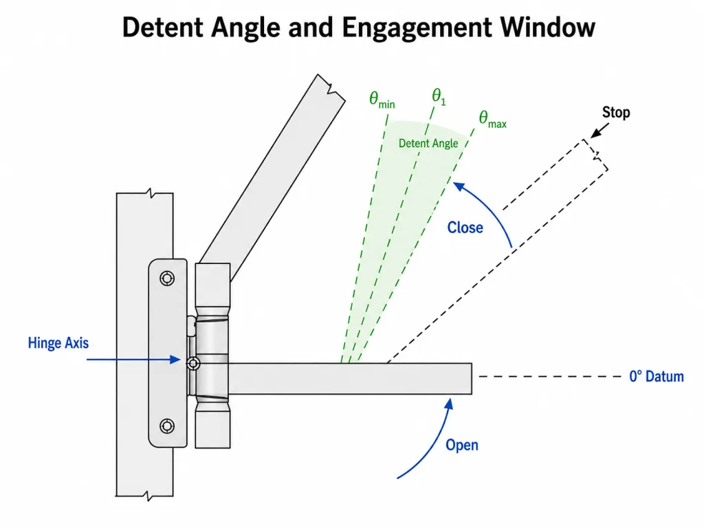
作図のルール: サプライヤーが、機器の図面に記載されているのと同じ0°の基準点および正の回転方向を特定できない場合、提示された係止角度はまだ比較の対象とはなりません。.
公称角度、ウィンドウ、および許容差
3つの角度の値は、それぞれ異なる挙動を表しているにもかかわらず、しばしば混同されてしまいます。.
名目上の役職
公称角度とは、θ など、意図されたインデックス位置のことです。1. これは図面基準に結びつける必要があります。θが1 デテント形状の理論上の中心、係合後のパネル位置の測定値、あるいはサプライヤーのカタログ表記のいずれかです。.
エンゲージメント期間
「エンゲージメントウィンドウ」とは、機構がインデックス位置への進入、捕捉、または定着を開始する領域のことです。ウィンドウの幅が広いと、パネルの位置決めは容易になりますが、動きのキレが失われる可能性があります。一方、ウィンドウの幅が狭いと、正確な操作感を得られますが、取り付け誤差、フレームのねじれ、およびマルチヒンジのずれの影響を受けやすくなります。.
角度公差と再現性
角度公差とは、部品やアセンブリ間の許容されるばらつきを定義するものです。再現性とは、同じ試料が繰り返し操作を行った際に、どの程度正確に元の位置に戻るかを表すものです。これら2つは同義ではありません。ヒンジの場合、図面の目標値から一貫してずれた角度で良好な再現性を示す一方で、生産ロット全体では平均値は正しいものの、個体間のばらつきが過大になることがあります。.
パネルの最終的な位置が重要な場合は、ヒンジレベルだけでなく、アセンブリレベルでも許容条件を明記してください。ヒンジ機構に問題がない場合でも、板金のたわみ、ブラケットのたわみ、締結具のクリアランス、およびガスケットの締付け力によって、パネルの位置がずれる可能性があります。.
「トルク」を解放し、「位置が特定されていない力」を解放しない
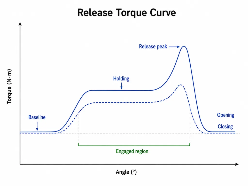
解放トルクとは、所定の条件下で、係合した止め金からヒンジを動かし始めるために必要な最大回転モーメントのことです。これはヒンジの軸を基準としているため、通常、解放挙動を説明する上で最も汎用性の高い指標となります。.
力の値は人間工学の観点からは依然として有用ですが、力の作用位置を明記する必要があります。同じヒンジであっても、大きなパネルの端では軽く感じられる一方で、操作者が軸の近くを押すと重く感じられることがあります。.
予備的な関係: 手動操作に必要な力 ≈ 解放トルク ÷ ヒンジ軸からの垂直距離。重力、シール、ケーブル、摩擦、および運動方向などがそれぞれ独自のモーメントを加えるため、組み立て全体ではこれよりも大きな力、あるいは小さな力が必要になる場合があります。.
サプライヤーの測定値については、それが最大ピーク値であるか、複数のサンプルに基づく平均値であるか、あるいは限界値であるかを明記する必要があります。また、ピークの検索に使用した角度範囲も明記する必要があります。ある試験システムでは狭いスパイクを捉えることができる一方で、別のシステムではフィルタリングや粗いサンプリングによってそのスパイクが平滑化される場合があります。物理的なヒンジが同じであっても、測定値は異なる場合があります。.
治具の設計、速度制御、トルク・角度の記録、およびデータ処理については、以下のガイドを参照してください。 ヒンジのトルクの測定方法. このページでは、これらのメソッドを、デテント解除の結果として何を報告すべきかを定義するためにのみ使用しています。.
デテントでの保持
カチッという音がしたからといって、ヒンジがパネルにかかる所定の荷重に耐えられるとは限りません。作動した機構は、重力、加速度、ケーブルの引っ張り力、シール力、ユーザーによる接触、あるいはその他のプロジェクト特有の荷重によって生じる外力に耐えられなければなりません。.
| 要件 | サプライヤーへの質問 | アセンブリチェック |
|---|---|---|
| 静止保持 | 完全に噛み合った止め金具は、位置から外れることなく、どの程度のトルクに耐えることができますか? | 設置された向きで、実際のパネルのモーメントを適用する |
| 放出閾値 | 各方向への動きを開始させる最大トルクはどれくらいですか? | 対象の手の位置におけるオペレーターの労力を測定する |
| 遊びまたはバックラッシュ | デテントが係合したままで、どの程度の角度移動が許容されますか? | パネルの目視による動きと機能上のクリアランスを確認する |
| 過渡負荷 | 定格には、衝撃、振動、または輸送時の荷重は含まれていますか? | 静的なリリース値から動的な容量を推測してはならない |
| 全行程荷重 | この止め金は、最大開度での衝撃が繰り返し加わっても耐えられるよう設計されていますか? | その機能が明示的に定格されている場合を除き、別の構造用ストッパーを使用してください |
保持と解放は、同じカムやスプリングの形状によって関連している場合がありますが、それらが同一であると想定すべきではありません。試験方向、滞留時間、予荷重、および「動き」の定義によって、報告される閾値は変化する可能性があります。両方が重要な場合は、両方の機能について確認してください。.
方向が変われば結果も変わる
デテントは、開方向と閉方向からそれぞれ接近した場合、異なる挙動を示すことがあります。内部カムの形状、ばねの予圧、摩擦、重力、および組立荷重によって、進入ピークと解放ピークが異なってくる可能性があります。試験データによってその選択が裏付けられない限り、仕様書では両方向に対して同一の値を使用すべきではありません。.
- 進入方向を指定してください 各クリック角度ごとに。.
- 登録と解除を別々に記録する そのメカニズムに顕著なキャプチャーピークまたはブレイクアウトピークが見られる場合。.
- 試験速度を定義する 潤滑剤の反応や動的な影響によって、測定されたピークが変化する可能性があるためです。.
- 滞留時間を定義する リリース前の状態で、使用中はパネルが止め金に固定されたままになります。.
- 状態の温度と事前調整 その機構に、潤滑部品、ポリマー部品、ばね、または摩擦部品が含まれている場合。.
- 治具の種類と向きを特定する したがって、重力や取り付け時のたわみなどが、説明なしにヒンジのみの値に混在することはない。.
サプライヤーの報告書には、トルク-角度の推移曲線、あるいはリリース値が発生した箇所を特定するのに十分な生データが記載されている必要があります。ラベルのない単一の数値だけでは、それが開閉時、新しいサンプル、事前にサイクル処理済みのサンプル、あるいはパネル全体から得られたものなのかを判断することはできません。.
2つのヒンジは互いに噛み合う必要がある
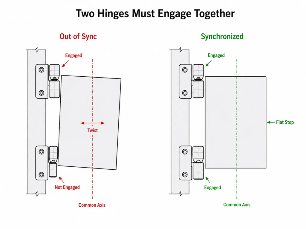
ペアでの組み立てには、もう1つの仕様上の問題、すなわち「タイミング」が生じます。一方の止め金がもう一方より先に噛み合うと、パネルが歪んだり、取り付けブラケットがねじれたり、あるいは「カチッ」という音が2回聞こえるような感覚が生じたりすることがあります。解放トルクを上げてみても、このズレは解消されません。.
2つの「90°」ヒンジでも、なぜ動きが固まることがあるのか: サプライヤーAは、閉じた取り付け葉の平面から止め金の中心を定義し、その角度公差を管理しています。 サプライヤーBは、基準点や許容範囲を明記せずに、カタログ上の公称位置として90°を指定しています。両部品とも同じ取り付け穴に適合します。組み立てられたパネルでは、片側がもう一方より先に噛み合い始めるため、フレームがねじれ、操作者は2回目のカチッという強い感触を覚えます。問題は、公称角度そのものではなく、同期にあります。.
これはあくまで例示的なエンジニアリングシナリオであり、顧客プロジェクトの実績や製品試験の結果を示すものではありません。.
2つのアクティブ・デテントヒンジを使用する場合は、共通軸、取り付け基準面、個々の角度公差、ペア間のタイミング、およびフレームの剛性を管理する必要があります。別の構成として、アクティブ・デテントヒンジ1つとフォロワーヒンジ1つを組み合わせる方法もありますが、その場合は、アクティブユニットとブラケットが所定の位置決め荷重を支える必要があります。適切な配置は、パネルの構造や入手可能なサプライヤーのデータによって異なります。.
パネル全体のテストを行う
ベンチ用治具では、ヒンジ機構の検証は可能ですが、機械にかかるあらゆる力を再現することはできません。最終試作品には、量産仕様のブラケット、締結部品、ケーブル、シール、パネルの質量、重心、および構造上のストッパーなどをすべて取り付けて検証する必要があります。.
図面通りになる可能性はありますが、パネルが意図した位置からずれてしまうこともあります。.
| 議会の傍聴 | 考えられる原因 | 再確認すべき事項 |
|---|---|---|
| パネルは、反対方向から異なる角度で係合する | バックラッシュ、方向依存性のカム挙動、またはブラケットのたわみ | 開口部および閉口部のトレース;基準面;アセンブリの剛性 |
| 「リリース」は「ヒンジ・レポート」よりもはるかに重みを感じさせる | ショートハンドレバー、重力、シール圧縮、ケーブル力、または軸の誤差 | 実手点と完全なモーメント平衡 |
| パネルを取り付けていない状態では位置は正しいが、パネルを取り付けるとずれてしまう | 外力モーメントまたは構造物のたわみ | パネルCG、ブラケットの剛性、および係合保持要件 |
| ある位置の近くで2回のクリックが発生する | 対になったヒンジは、それぞれ異なるタイミングで噛み合う | 角度公差、共通軸、フレームのねじれ、およびヒンジの整合 |
| 繰り返し使用すると、止め金の動きが変わる | 摩耗、予圧の変化、取り付け時の動き、または潤滑剤の交換 | サイクル後の角度、解放トルク、および締結部品の状態 |
サンプル承認書には、承認された図面の改訂内容、ヒンジの識別情報、試験方向、角度測定結果、リリース結果、パネル構成、およびプロジェクトで要求されるサイクル後の変更事項をすべて記載する必要があります。承認限界値が記録されていない手動操作のサンプル1つに基づいて、生産を承認してはなりません。.
サプライヤー仕様書を作成する
見積依頼書(RFQ)は、実用的な長さでありながら、比較に必要な情報が十分に盛り込まれている必要があります。以下の構成により、要件は一般的な調達プロセスではなく、デテントの動作特性に焦点を当てたものとなっています。.
デテントヒンジ機能
- 用途および可動パネルの説明:
- ヒンジの数量および配置:
- 必要なデテント位置:
- 位置間の動作要件:
- 別途の構造的ストッパー:あり/なし/サプライヤー指定のデテントストッパー

角度の定義
- ゼロ角度基準:
- 正の回転方向および視認側:
- 公称デテント角度:
- 各位置における係合範囲:
- ヒンジレベルの角度公差:
- 完全組立時の角度公差:
- 接近方向:開方向/閉方向/両方
- 係合中の許容バックラッシュまたは動き:

トルクおよび荷重
- 各方向における解放トルク限界:
- 解放ピークを特定するために使用する試験角度範囲:
- 各デテントにおける必要な保持条件:
- 外部パネルにかかるモーメントまたは荷重条件:
- 操作力が重要な場合、ユーザーの手の位置:
- 進入または捕捉動作の要件:
- 必要に応じて、デテント間の基準抵抗:

試験条件
- 試験方向および治具:
- 回転速度:
- 解放前の保持時間:
- 温度:
- 予処理サイクル:
- サンプル数:
- データ報告方法:
- 必要に応じて、初期およびサイクル後の合格基準:

図面およびトレーサビリティ
- サプライヤーの部品番号および改訂版:
- 材質および表面処理:
- 取り付け寸法および基準点:
- 左右または方向指定のあるバージョン:
- サンプルまたはロットの識別情報:
- 必要な報告書または曲線:
このガイドを参考にして、 ヒンジの仕様書および設計図面 また、そのプロジェクトでは、寸法、修正、公差、および図面の責任者についても、より広範な見直しが必要となる場合。.
審査用のデテント要件を送信する
組立図、角度基準、必要なインデックス位置、接近方向、許容解放トルク、パネル荷重、ヒンジの数量、動作環境、および予想サイクル数をお送りください。HSPはこれらの情報をもとに、仕様書に不足している項目を特定し、入手可能な情報と比較することができます。 止め金付きヒンジのモデル.
デテントヒンジの仕様に関する質問
止め角は最大開角度と同じですか?
必ずしもそうとは限りません。デテント角度とは、所定の位置を指します。最大開度には追加の移動量が含まれる場合があり、通常は、サプライヤーがデテント機構に対して繰り返し停止荷重への耐性を明示的に定めていない限り、別の構造上のストッパーによって制御されるべきです。.
保持解除トルクと保持トルクは同じ値であるべきでしょうか?
これらを同一のものだと見なしてはなりません。解放トルクとは、所定の条件下で係止状態から動きを開始するために必要な最大トルクを指します。保持力とは、係合した機構が耐えることができる外力(モーメント)を指します。方向、保持時間、試験方法、および動作基準によって、報告される値は異なる場合があります。.
解放トルクの代わりに解放荷重を指定することはできますか?
はい、ただし、力の作用点、方向、パネルの形状、およびヒンジ軸からの距離を定義する必要があります。通常、トルクの方がサプライヤー間の比較が容易ですが、力はパネル全体にかかる作業者の負荷を確認するのに役立ちます。.
なぜ2つのデテントヒンジは、異なるタイミングで噛み合うことがあるのでしょうか?
個々の係止角度、角度公差、取り付け基準点、ヒンジ軸、あるいはフレームの剛性が、十分に一致していない可能性があります。1つのヒンジが先に係合し始め、2つ目のヒンジが係止位置に到達する前にパネルをねじってしまうことがあります。.
デテントヒンジの審査において、サプライヤーはどのようなデータを提出すべきですか?
図面の修正、角度基準、公称保持角、係合範囲、角度公差、接近方向、各方向の解放トルク、保持条件、位置間の挙動、試験速度、滞留時間、温度、サンプル数量、トルク・角度の証明資料、およびサンプルの識別情報を要求してください。.